Forum Replies Created
-
AuthorPosts
-
 BRONZE Member
One could also use MP3 sine wave test tones which might make it easier to do comparisons. Glitch
Yes I agree..
Location: Hampshire, England
 BRONZE Member
Given you only have a basic multi-meter you could try the following, it is a long shot, but worth a try.
With a signal (music would be best) plugged into the phono socket use you multi-meter set to AC volts say 1 volt range if it has one, or the lowest available. What we are trying to do here is measure an analogue signal with a AC volt meter and compare the good speaker with the bad.
One meter lead on P2 pin 2 and the other lead on each of the following points on both speakers with the same music input.
- Both sides of C75
- IC1 pin1
- Both sides of R136
- Collector of Tr16
Note any points between the two speaker with a difference.
Location: Hampshire, England
 BRONZE Member
I was afraid that would be your answer because operational amplifiers are normally very reliable.
With regards to damaged copper track caused by foam rot, yes that certainly could be the cause. Because the damage often cannot be seen, only a continuity test between each of the components in the circuit around IC1 and all the components around it will answer the question for sure. Also one of the capacitors could also be at fault or at least well out of tolerance.
Without an oscilloscope your work is now testing components typically by replacing.
Location: Hampshire, England
 BRONZE Member
Whilst the Plus and minus power connections are a little low, it should still work..
You should change IC1 assuming you have the desoldering equipment available to do the job
Location: Hampshire, England
 BRONZE Member
That’s because you have put your multi meter between pins 4 & 8 when you should have measured between ground point and pin 4 and again between ground point and pin 8.
Note my statement in the previous post which said “That means between a ground point and pin4 and the same with pin 8”
Location: Hampshire, England
 BRONZE Member
Thank you for your latest information.
Remembering that we are only measuring DC voltages meaning it can only show up general irregularities, not analogue signal..
The voltage at the base of TR14 is in line with what I would expect. This supports the likelihood that the fault is prior to R136 with further support from the fact that you accidently used you meter in diode/continuity mode which triggered TR16 and switched the unit on.
I am assuming that you previously check the +15 and -15 volts on pins 4 & 8 of IC1? That means between a ground point and pin4 and the same with pin 8
Whilst the problem could still be one of the components around IC1, you should change IC1 as the next step..
Location: Hampshire, England
 BRONZE Member
This is exactly what I mean’t, thank you.
Clearly it is difficult without a scope and doing these voltage checks can only be a general guide.
However the 0.8 volts DC at the base of TR14 is much nearer to what I would expect.
It is starting to look like IC1 or one of the associated resister/capacitor around the IC could be at fault or well out of tolerance.
Before you change the IC1, lets do one other check by removing R136 add a input to the phono and measure the DC voltage at TR14 base again.
Location: Hampshire, England
 BRONZE Member
You need to clarify your use of the words diode/continuity mode?
We are testing the DC voltage at each of these points..
Location: Hampshire, England
 BRONZE Member
Whilst I have not needed to look at a Beolab 8000 for a very long time, I took time to remind myself of the workings of the circuit.
To answer your last question first, the problem could be IC1 and I noted you have tested all parts of PCB5 by comparing with a working unit.
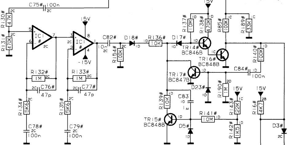
Given everything works perfectly with a Powerlink connection is helpful because that reduces the area for investigation considerably. The problem is almost certainly going to be prior to R85 on PCB2 where it feeds the base of TR9. The reason I say this is because where you use the Powerlink to switch on the speakers it forces the collector of TR16 which feeds the other end of R85.
If you have an oscilloscope I would look at the anode of D17 which is also the junction of R136 and the collector of TR17 with and without a signal at the phono input.
If you only have a multimeter, then the best way is comparing voltages between a good unit at the bases of TR14, TR16 and TR17 with and without a signal at the phono input.See attached circuit diagram of the area of concern
Let me know how you get on..
Attachments:
You must be logged in to view attached files.Location: Hampshire, England
 BRONZE Member
The so called “Special Remote” is not so special it just adds a REG1 & REG2 command as you will see in the attachment.
Location: Hampshire, England
 BRONZE Member
Alternatively, the IR codes of this region free command can be incorporated in the Beo5/6 remotes.
I have attached a ZIP file containing the XML file I built many years ago, which you can add to a Beo5/6 remote with the commands used in the instructions already supplied.
Location: Hampshire, England
 BRONZE Member
 BRONZE Member
I’m really not sure how long I have been a member of the site
Thank you for your kind feedback.
You joined Beoworld on 11th April 2016 at 7:40am and your member ID is 45901The latest member to join Beoworld has a member ID of 87909
Location: Hampshire, England
 BRONZE Member
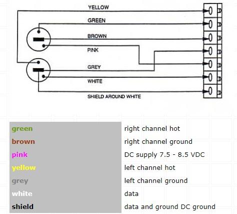
On all MCL products the datalink is on the 3rd pin of the speaker socket.
Location: Hampshire, England
 BRONZE Member
One thing which is not mentioned is if it will affect the member status/payment? The reason for asking is that my membership renewal is coming up, and I would like to know if there should be any reason for not paying before the transfer to the new ownership?
Whilst I cannot speak for the new owners and their future plans, initially anyway everything will remain the same. HOWEVER payment is taken by debit/credit cards and as part of our agreement I will be cancelling our agreement with our credit card processor (Global Payments). When it is cancelled a message will be added to the web site asking members to pause renewal payment until the new owners payment system is in place.
Location: Hampshire, England
 BRONZE Member
I am pleased to announce that last Thursday, Lee and I signed a sale agreement whereby Beoworld is to be handed over as a going concern, meaning the new owners (Multicare Electronics Ltd) will continue the sites as they are today, initially anyway.
The sale will include everything that exists today on-line plus thousands of hard copy manuals, brochures and B&O technical/repair documents.
Under the agreement the transfer will take place over a period of up to 8 weeks starting last Thursday 15th February 2024. The first steps are for the new owners to setup their servers. The live forum runs on Linux, but everything else runs on Windows servers which also require SQL servers to be installed.
It is intended that during the transfer period the web site and forums will continue as normal, except for a period when the Domains (Beoworld.org) is transferred from our registrar account to theirs. Advanced notice will be given of the timing (Date & Time) of the Domain transfers and typically it could be up to eight (8) hours for the transfer to be completed assuming no issues are encountered.
After the transfer, everyone’s accounts will remain the same as today because all the databases will have been transferred as part of the process.
For me, this is a emotional period, given the years I have worked keeping Beoworld going, but I have accepted that it is time to pass the baton to others..
I would like thank everyone who has supported Beoworld over the years including you, our members as well as moderators past and present. I will be emailing all Gold and Silver members with details of the sale agreement. We still have 35 “Founder” members who are still paid up Gold members for which I want to offer a special thank you.
Regards
Keith..
Location: Hampshire, England
 BRONZE Member
The BC6-23 can be an audio master if required, but by default it is not.
When an FM or DAB radio is fitted to a BC6-23 which it was if purchased in the UK, then if you press “Radio” on the remote it would play using the audio master via the masterlink. If you wanted to play the radio fitted in the BC6-23, then you use “LINK” found in the “LIST” followed by “Radio”
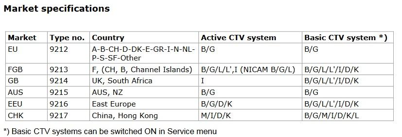
There are several variations of the BC6-23 depending on type number/country or MArk 1 or 2
Location: Hampshire, England
 BRONZE Member
It should be noted that there are several versions of the BeoVision 1 which have the letters “L” or “LS” after BeoVision 1.
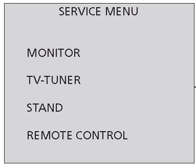
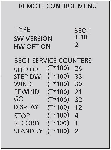
Note all versions had the “Remote” in the service menu, but I think the BeoCentre 1 did have the full remote. If there was “Remote” in the Service Menu then it looks like the following:-
Location: Hampshire, England
 BRONZE Member
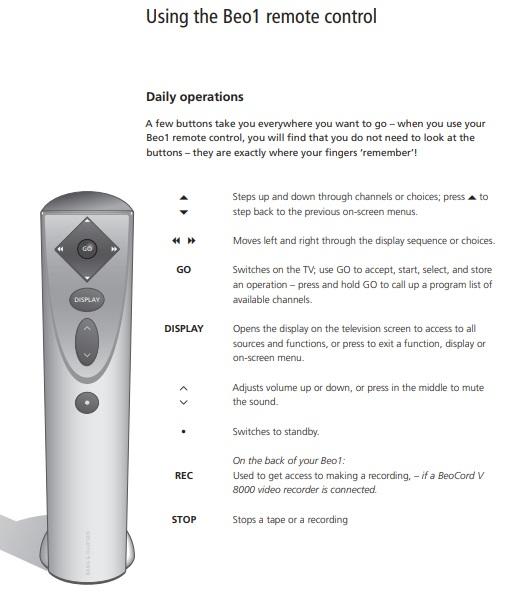
There is no procedure to “pair” the remote because it is a standard IR remote.
The remote can ONLY be used with the Beovision 1 or the Beocentre 1
Location: Hampshire, England
 BRONZE Member
Please find attached the Christmas edition of Beotalk from 1976 and the August 1976 edition.
Location: Hampshire, England
-
AuthorPosts

