
Forum Replies Created
-
AuthorPosts
-
16 January 2026 at 10:59 in reply to: Beomaster 3000-2 Type 2402 15V Power Supply Not Activating #72597
 hcraig244SILVER Member
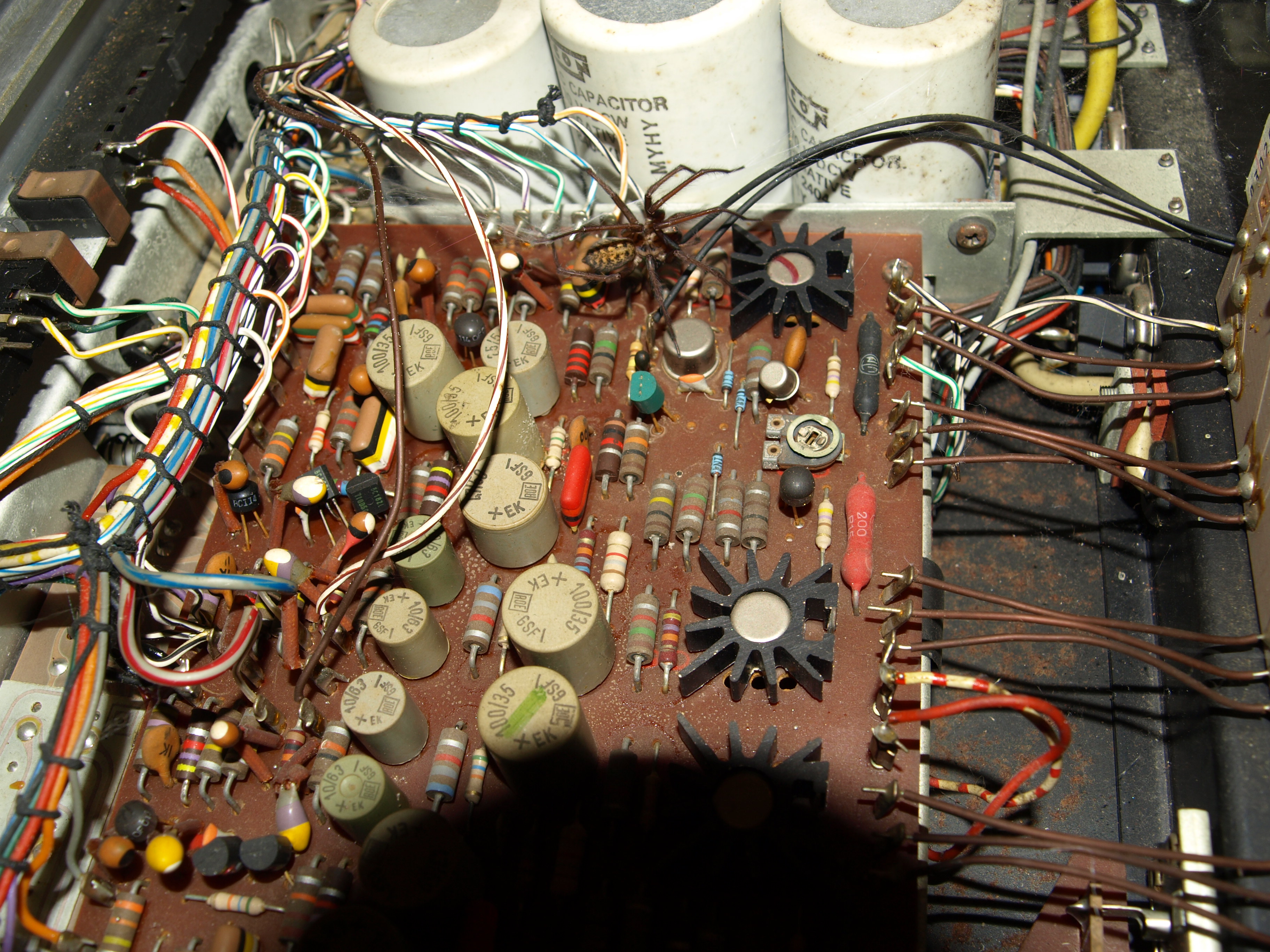
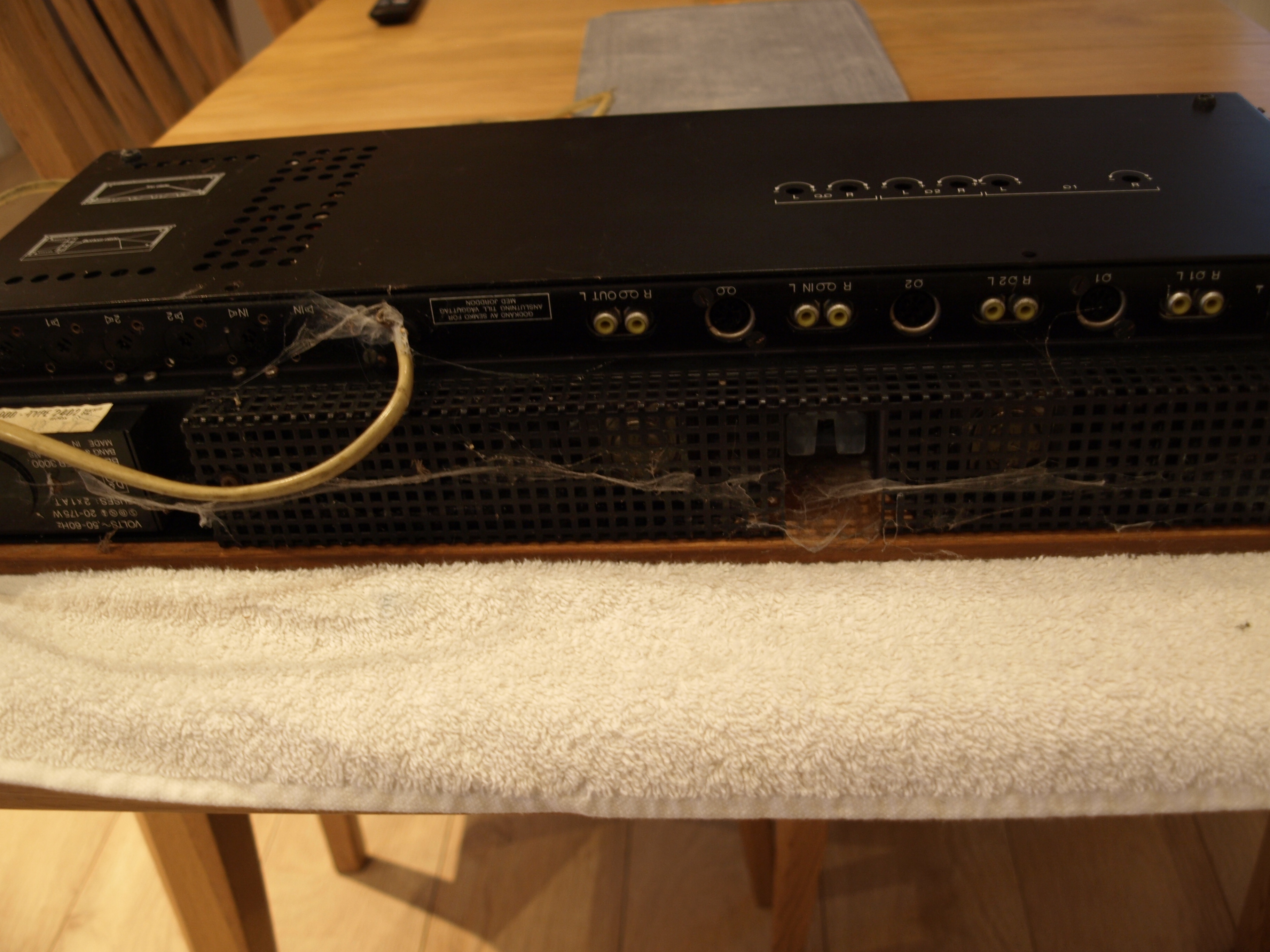
A look underneath reveals more potential horrors……
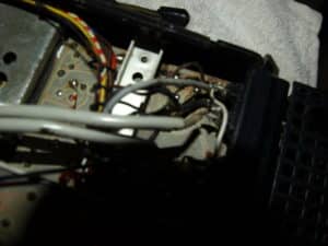 16 January 2026 at 10:56 in reply to: Beomaster 3000-2 Type 2402 15V Power Supply Not Activating #72594hcraig244SILVER Member
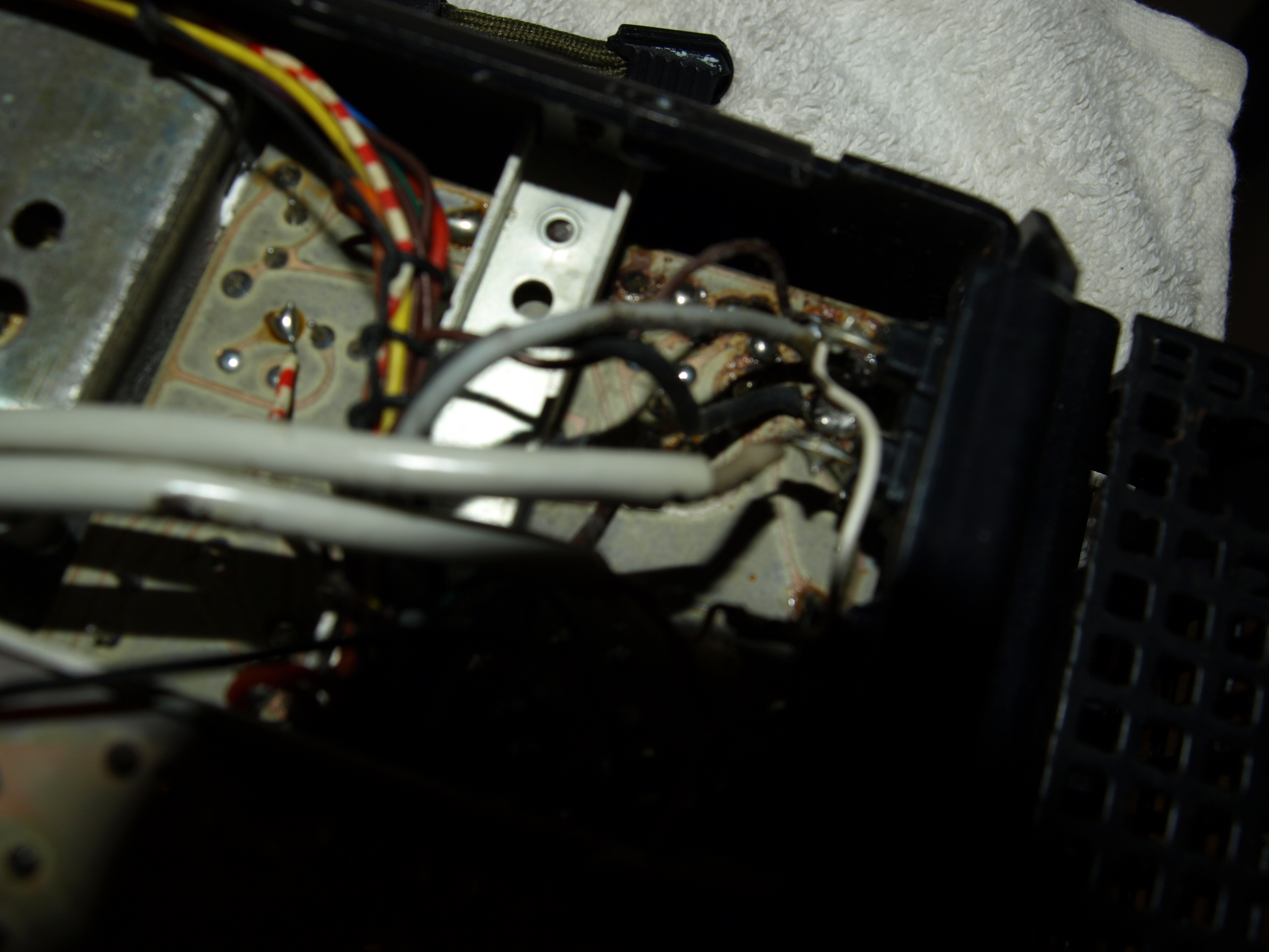
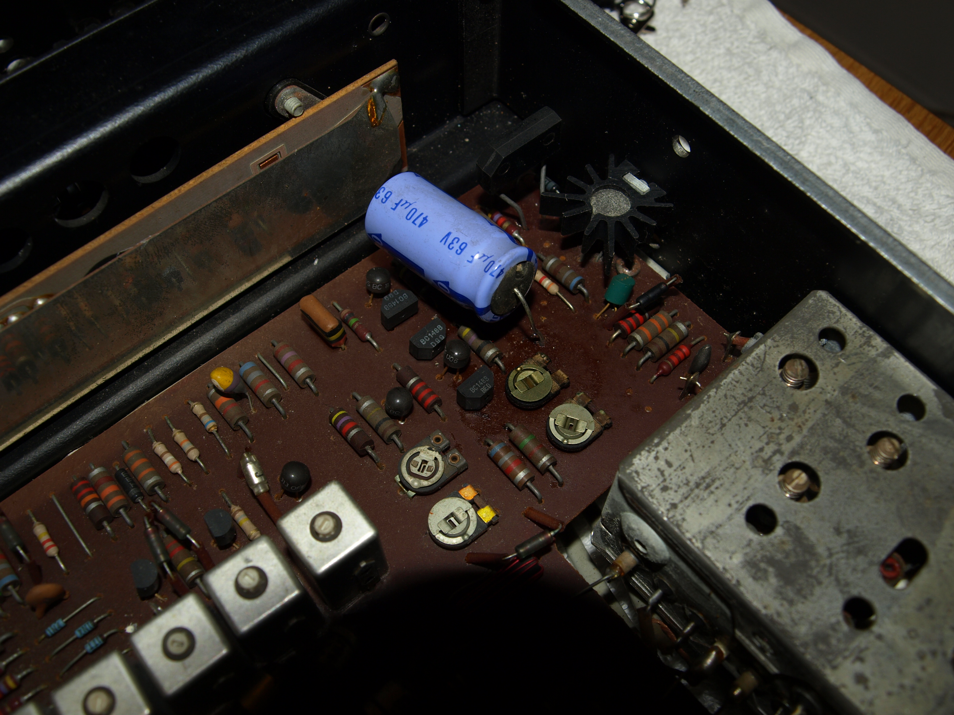
Dusting out has revealed a probem in the 15v power supply, someone has been here before me and wielded a soldering iron, the smoothing cap that has been replaced has a loose leg!
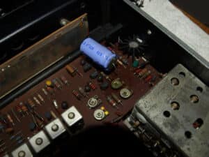 15 January 2026 at 18:17 in reply to: Beomaster 3000-2 Type 2402 15V Power Supply Not Activating #72581hcraig244SILVER Member
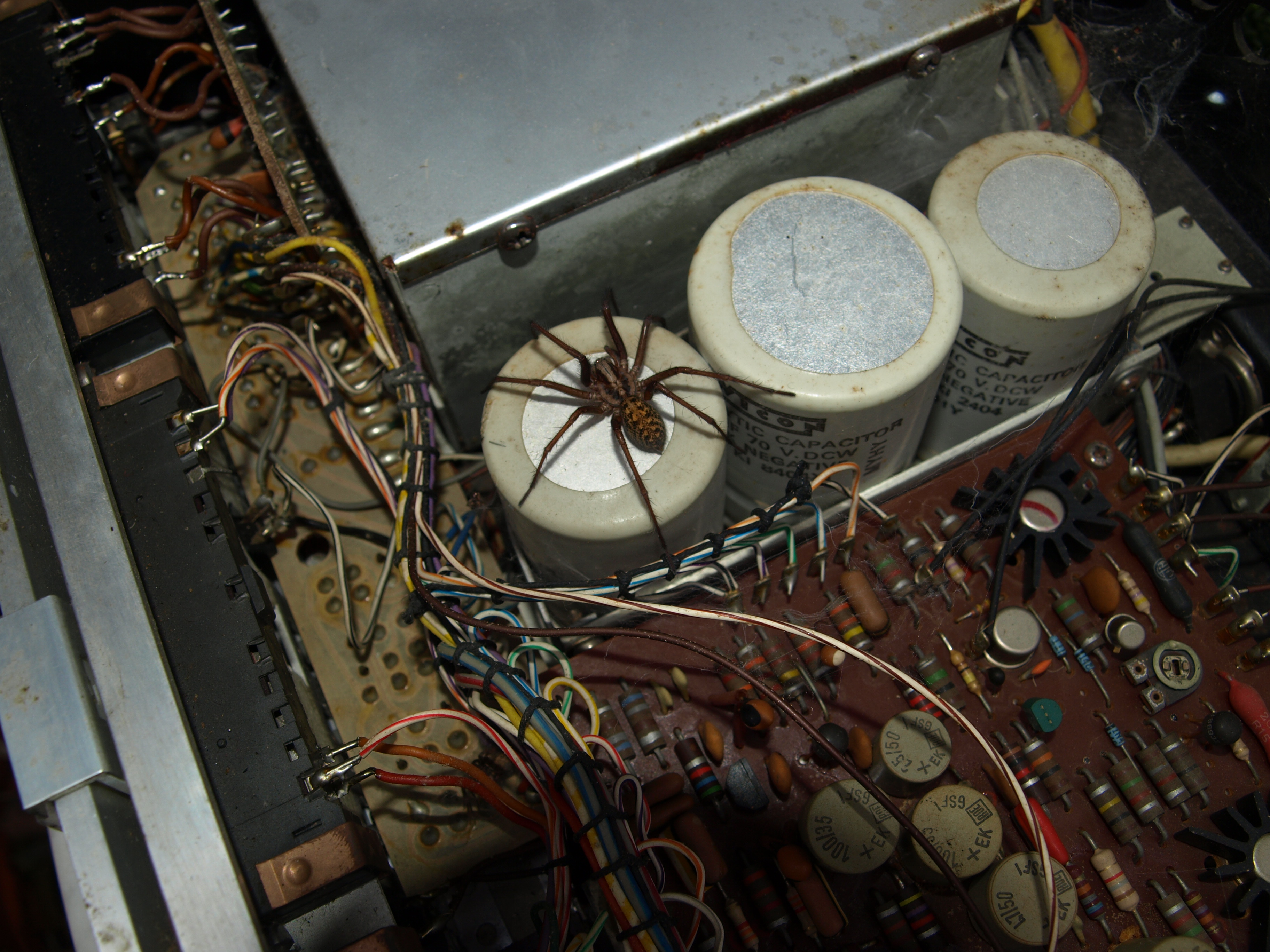
took it outside and let it go….hope it doesn’t come back into the house! will have a bit of a clean in here and make sure it all looks well before powering up…..i suspect it wont come to life or I wouldn’t have acquired it.
15 January 2026 at 18:14 in reply to: Beomaster 3000-2 Type 2402 15V Power Supply Not Activating #72580hcraig244SILVER MemberLook at this bad boy….
 15 January 2026 at 18:13 in reply to: Beomaster 3000-2 Type 2402 15V Power Supply Not Activating #72578hcraig244SILVER Member
looking inside i discovered I was not alone in there…
15 January 2026 at 17:57 in reply to: Beomaster 3000-2 Type 2402 15V Power Supply Not Activating #72571hcraig244SILVER Memberfound this in the bowels of the workshop, suspected I had one but wasn’t sure…dont even remember acquiring it to be honest!
looks a little sorry for itself…i think I must have bought it several years ago and not got around to it15 January 2026 at 09:59 in reply to: Beomaster 3000-2 Type 2402 15V Power Supply Not Activating #72559hcraig244SILVER MemberI think I have a 3000-2 floating around somewhere…..i’ll have a look for it and if i find it i will take some measurements for you, you’ll need to be specific which points to measure
Craig
12 January 2026 at 08:15 in reply to: About to start my 2nd Beomaster 4400 restoration – need tuner restring advice #72502hcraig244SILVER MemberI thought there was a manual in the products section for the 4400….however when I look I can no longer find it? as I recall it gives the details required to replace the tuner string, I think I have one somewhere and will have a look for you.
Craig
7 January 2026 at 17:57 in reply to: Beomaster 3000-2 Type 2402 15V Power Supply Not Activating #72412hcraig244SILVER MemberProgress…..I have also found a number of instances where the circuit diagram has been in error….I always take pictures of the units I work on before disconnecting or replacing items, I have also found instances where the actual markings on the PCB have been wrong.
You should replace all of those skeleton trimmers as soon as possible…if they let go you can blow your output transistors…and after all these years they are quite fragile…encapsulated trimmers are easy to obtain…a good idea would have been the purchase of a kit from dillen which contains all the recommended replacement components ;¬)
Craig
hcraig244SILVER MemberCheck out these two links….there are a couple of different designs….
https://beolover.blogspot.com/2020/08/beogram-4000-mmc-cartridge-mount-replacement.html
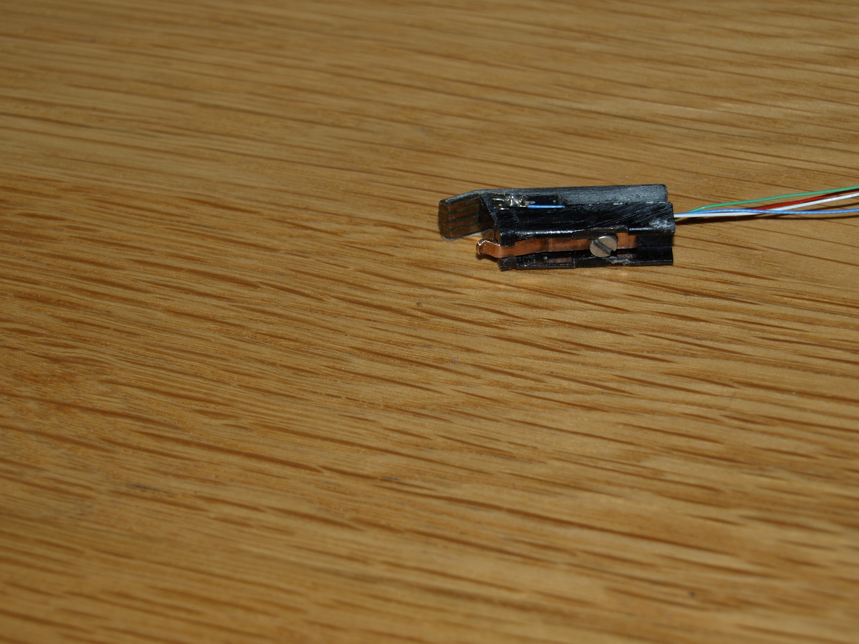
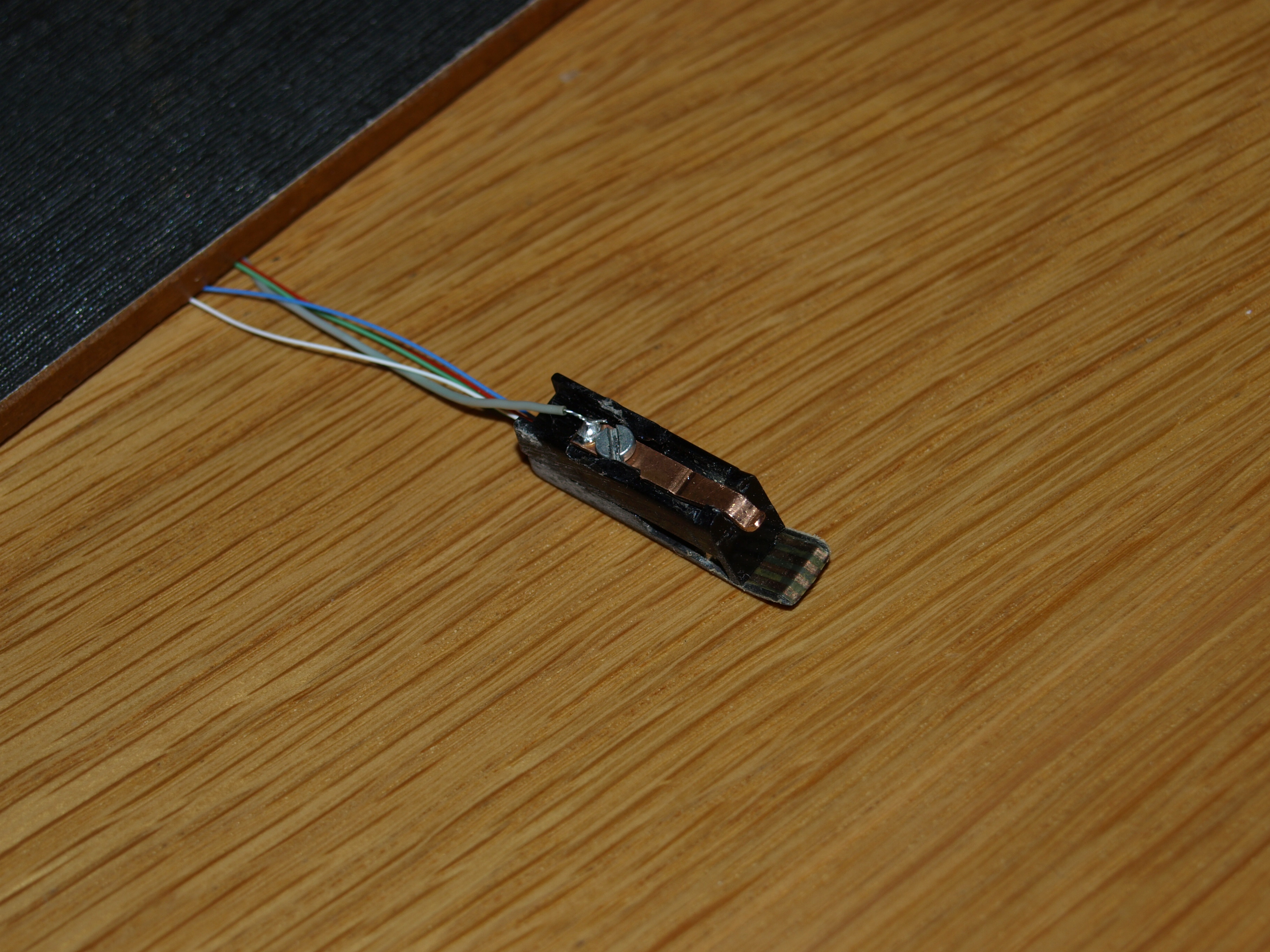
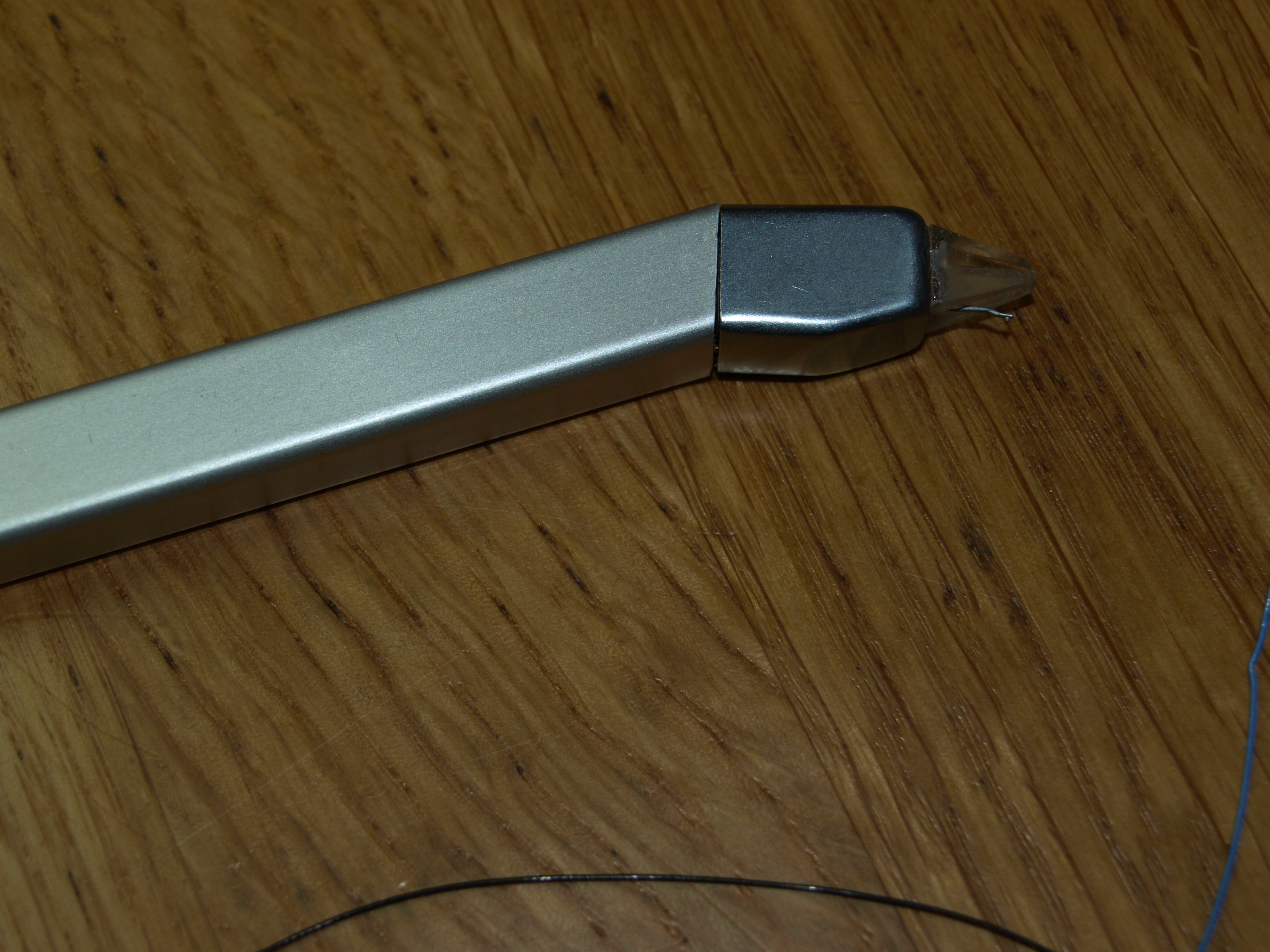
hcraig244SILVER MemberBe very careful when removing or installing the cartridge, the plastic connector will be very brittle and susceptible to fracture, many have suffered this fate. As Mark says it looks very much like the cartridge isnt seated correctly on the grounding tab (copper spring that grounds and also helps keep the cartridge in place) make sure the slot at the bottom of the cartridge is free of any debris. These arms can be repaired however its a fraught excercise that requires a degree of destruction prior to rebuild, and of course purchase of custom 3d printed parts, available from Rudi at a cost….dont bend the copper spring, is meant to be shaped to fit….there is a distict “click” when the cartridge is fitted correctly.
This is one i repaired with a 3d print and self fabricated spring…
Should fit like this…..hopefully you only need to align yours correctly and it will ir snugGood luckCraighcraig244SILVER MemberI have been involved in a good number of BG4000 repairs/restorations over the last 10 years or so…..the two in my possession where purchased as spares or repair over 7 years ago for around £150. I spent perhaps £60-£100 on parts, components etc on each…and in one case many hours chasing down an intermittent fault that ate my lunch for weeks….I also relied on the expanse of knowledge and support from the members on this site. I now see, as everyone else on the site, the same decks offered….and in some cases sold, for eye watering prices. I actually think the decks are worth these sums once repaired and fully functioning, the 4000 is massively over engineered and the means by which the end has been achieved by B&O looks to be the most complex and complicated procedure imaginable given the technology of the day…. to introduce a deck of the same quality and engineering excellence into todays markets would be prohibitive, as can be seen by the price tag placed on the 4000C upgrades offered currently……..for some of us its not an investment/earning opportunity its more a passion for quality.
Personally I prefer the 4000 series over the 4002 due to the inherent complexity of the machine, this does however bring with it the regular hiccup’s associated with such old equipment….which most of us actually enjoy resolving…for me you should consider your motivations before shelling out £1,700 for a potential return down the road.
Craig
hcraig244SILVER MemberPost a couple of pictures…..may help diagnose the problem for you
Craig
22 December 2025 at 12:50 in reply to: Beomaster 3000-2 Type 2402 15V Power Supply Not Activating #72058hcraig244SILVER MemberThis is where a signal generator and oscilloscope come in real useful, you can track the signal path through the circuit until you pick up the distortion…….not much help I know 😳
15 December 2025 at 11:47 in reply to: Beogram 4002 – Arm sensor not turning on, need help :) #71946hcraig244SILVER Memberyou may be lucky and only have to replace the lamp in the end of the sensor arm……good luck
Craig
15 December 2025 at 11:37 in reply to: Beogram 4002 – Arm sensor not turning on, need help :) #71945hcraig244SILVER Membercheck out beolovers blog on this…..may help you understand whats going on
https://beolover.blogspot.com/2022/05/beogram-Replacing-sensor-arm-bulb-with-led.html
15 December 2025 at 10:37 in reply to: Beomaster 3000-2 Type 2402 15V Power Supply Not Activating #71941hcraig244SILVER Memberdid you change the tuning indicator lamps in the tuning circuit? if so these must be replaced by lamps of the exact current pull….i had an issue with some i changed on a 4400, Dillen provided the correct lamps and all was well.
Craig
15 December 2025 at 10:31 in reply to: Beomaster 3000-2 Type 2402 15V Power Supply Not Activating #71940hcraig244SILVER MemberAlso bear in mind that some components can measure up fine when tested, but fail under load…..I’ve had this issue in the past, and replacement parts from suspect suppliers should be avoided…early transistors can still be found as old stock and are a safer bet than ebay
Craig
hehe…..
10 December 2025 at 18:19 in reply to: Simplest way to change Beomaster 4400 FM signal level lamp #71843hcraig244SILVER MemberI’ve had a similar problem in the past and with the help of a signal generator and an oscilloscope traced it to a noisy transistor in the pre-amp section as I recall….I’ll take a look at the circuit diagram and see if I can remember which one it was. There will be a post by myself in the archives detailing this im sure 🤔
9 December 2025 at 10:50 in reply to: Simplest way to change Beomaster 4400 FM signal level lamp #71822hcraig244SILVER MemberIt’s tricky…
You dont need to remove the front panel, thank goodness…..would be a shocking design defect if one did. The lamp is held in a holder that slides into the side of the moving coil meter, the holder has two wires soldered to it to illuminate the lamp therein. the meter also has two wires soldered on to it externally to power the moving coil, cant remember if its a moving coil or moving iron meter…..non the less it has two wires!
The meter is held in place on the front panel by a copper leaf spring which in turn is held in place by a single screw, see below. when this screw is removed the meter will push in from the front of the switch panel and be sort of accessible, the connecting wires are single strand and very unforgiving….the tugging and pulling required to remove the lamp holder in situ with all wires still connected is traumatic and in one case for me I broke a connection to the moving coil and had to replace the whole thing….fortunately Dillen from this site had a used one he let me have ;¬)
My approach of choice now is to snip the four wires that connect to the meter, well inside the unit for ease of re-soldering later, then undo the screw and spring thus allowing the meter to be removed from the underneath of the chassis, the lamp holder can then be slid out and a new lamp inserted and the meter re installed prior to re soldering the snipped wires. This is a very delicate operation, partly due to the frailty of the connections and getting the spring loaded screw back in place is also a challenge best done before soldering the wires back in place. You also need to replace the lamp with one with the correct ratings…Dillen can provide the correct one.Attachments:
You must be logged in to view attached files. -
AuthorPosts