
Forum Replies Created
-
AuthorPosts
-
 hcraig244SILVER Member
Beogram 8002
Thank you or your response, you identify some solid starting points to get to the bottom of the issues I have described…I will be addressing the issues for each 8002 in turn, probably starting with the one whose tone arm moves to the correct position but refuses to drop, as you suggest I’m hoping for a mechanical problem…I do hear what I believe to be the solenoid clicking in prior to the tone arm doing nothing….with the exception of the grounding hum I do have a fully functioning set which is always useful for comparison checks.
Regards Craig
hcraig244SILVER MemberMark
Thank you for your response to the above issues, I’m confident your correct in your assessment of the suitability of the existing cable. See below Dillens advice which is very much aligned with yours:
Beogram 8002 requires a double-shielded signal cable (PH).if you are using a cable meant for a Beocord (TP), you will almost certainly get hum.If you are using the correct PH cable, the problem could be a broken ground connection at, or near, the DIN Socket board in the Beogram or inside one end of the cable. At least that would be the first things to check.
I will be contacting Steve of Heavenly Sounds for a price and delivery of a suitable cable over this weekend.
Thanks again for your support
Craig
-
This reply was modified 3 months, 2 weeks ago by
 hcraig244.
hcraig244SILVER MemberSo there we have the project in summary:
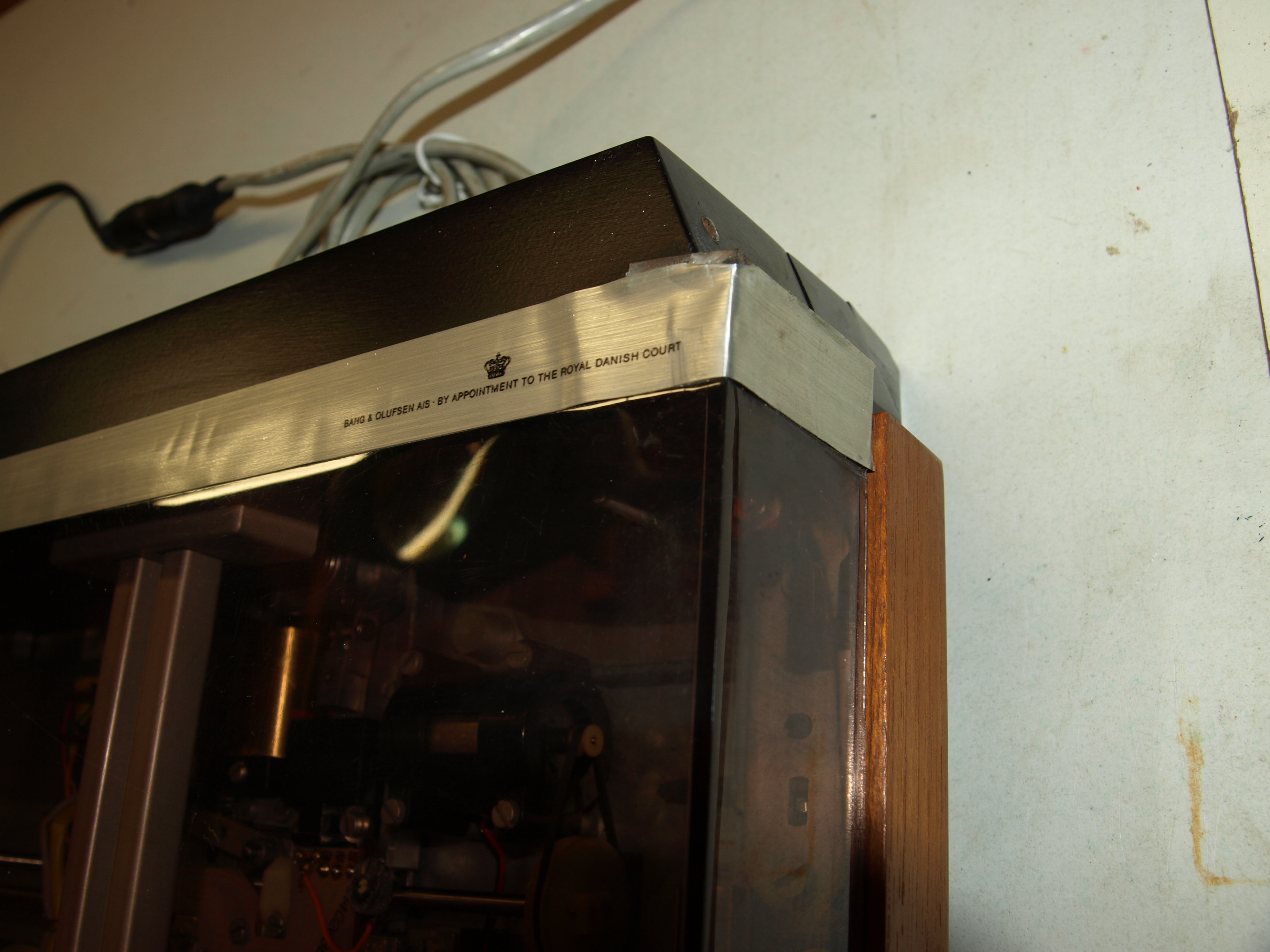
1 BG4000 in working order with some work on the dust cover trim
1 BG8002 in working order with a suspected ground hum/buzz going on
1 BG8002 mostly in working order, the buzz/hum is present here too, with the exception no tone arm drop, I’m suspecting something mechanical,
1 BG8002 with operational issues around the tone arm movement and possibly drop..the tone arm cover is loose so im suspecting it may have been looked at in the past.
As always any suggestions will be welcomed along with encouragement of course ;¬)
Attachments:
You must be logged in to view attached files.hcraig244SILVER Member3rd BG8002 on the bench…powers up fine and all lights illuminate when play is pressed, platter spins and tone are begins to move to the drop area when it stops short and stays there, wont stop and needs to be moved back by the reverse button at which point all goes back to standby….dont know if the buzz/hum is present?
Attachments:
You must be logged in to view attached files.hcraig244SILVER MemberOn checking the output cable provided by the owner i see its a 5 pin DIN to phone plugs….the DIN socket on the deck is a 7 pin…the service manual suggests a number of earth/ground connections are not getting picked up by the amps I am connecting too….
hcraig244SILVER MemberSecond BG8002 up for testing complete with platter and cartridge….all visual inspected fine, powered up and still looking good….however the tone arm refused to drop when asked….tried a couple of times to no avail, interestingly the hum/buss that I suspect is a grounding thing presents itself when the tone arm is asked to drop….I’m seeing a trend here
Attachments:
You must be logged in to view attached files.hcraig244SILVER MemberFirst one up fitted with platter and cartridge, powered up via variac and came up nicely…nothing untoward so went ahead and connected up to a BM6000 and although the sound came through on both channels there is an overriding hum that sounds very like a grounding issue…..tried with a BM3000 and also a Beolab5000 and the hum remains…..
Attachments:
You must be logged in to view attached files.hcraig244SILVER MemberI have been awaiting delivery of platters and cartridges for these three decks in order to determine status prior to ordering the required parts from Dillen, didnt want to order kits and then discover additional parts where required due to an unknown fault…saves shipping costs to buy everything in one go ;¬)
Platters and cartridges arrived yesterday so will be inspecting the first one today
hcraig244SILVER MemberI’m thinking all further pics will need to be via attachments as the definition is superior….next up for inspection the first of the BG8002 decks
Attachments:
You must be logged in to view attached files.hcraig244SILVER MemberWith no fault finding/repairs required, good news, a kit to include all the usual caps and trimmers along with drive belts will be ordered from Dillen and a straight forward replacement carried out…..the trim will need attention, it has been repaired once before but needs a little more work
Attachments:
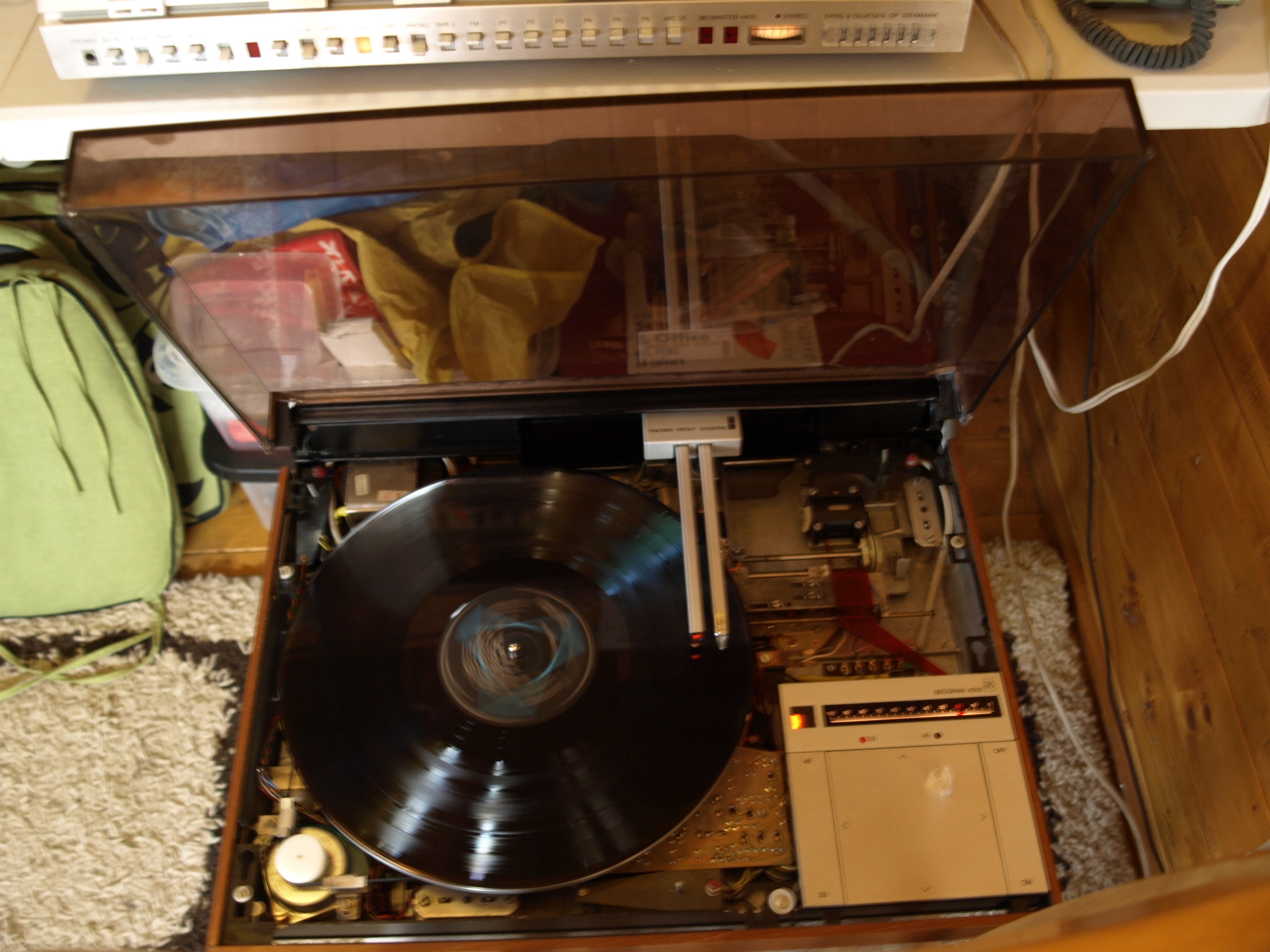
You must be logged in to view attached files.hcraig244SILVER MemberPowered up via the variac and all is well, no smell of burning or sudden cracking of blowing fuses….hooked up to a BM4400
 hcraig244SILVER Member
However the dust cover looks like some work has been carried out, this will require some attention…
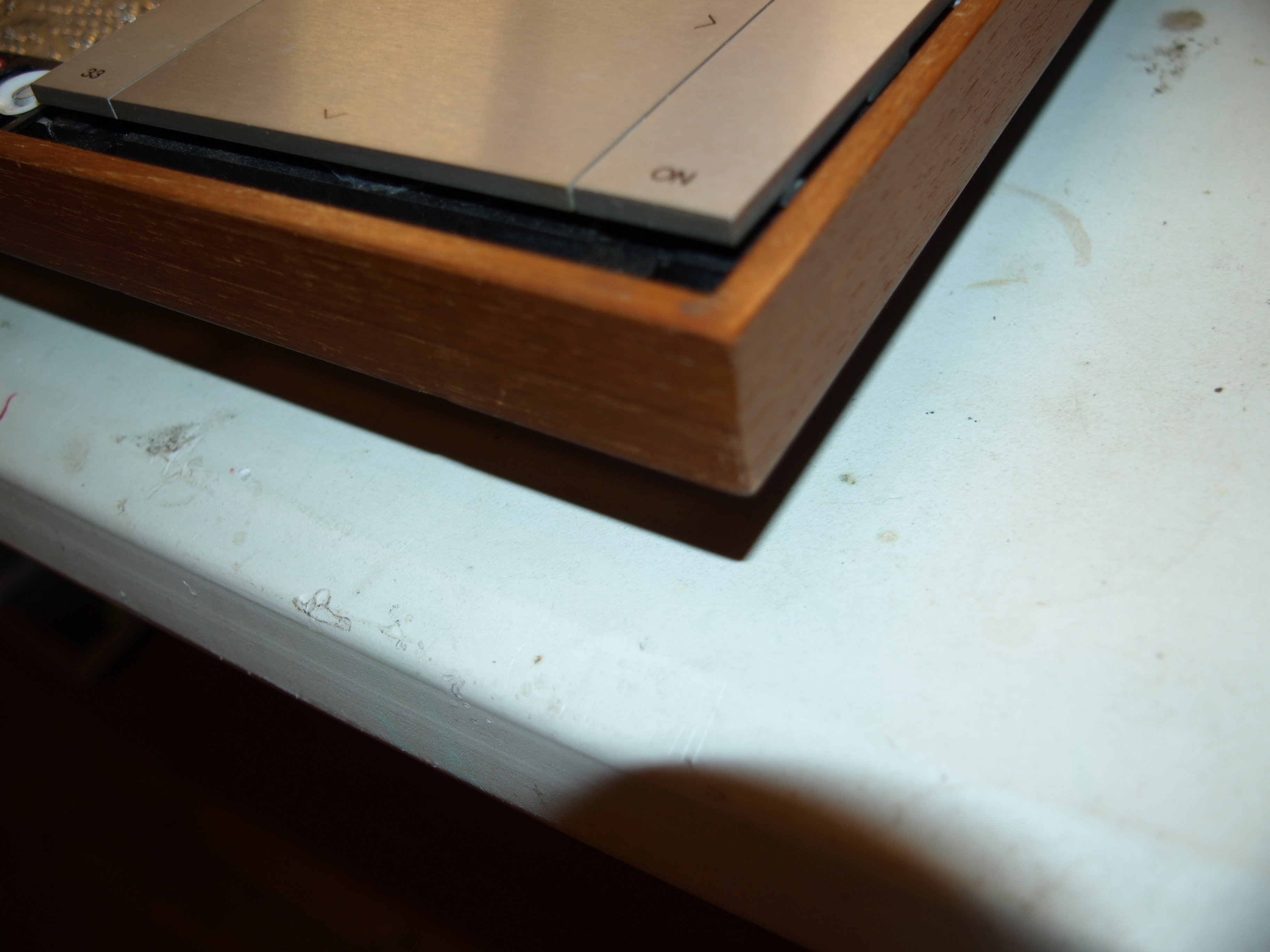
The wood trim looks in good shape with all corners still sharp and clean
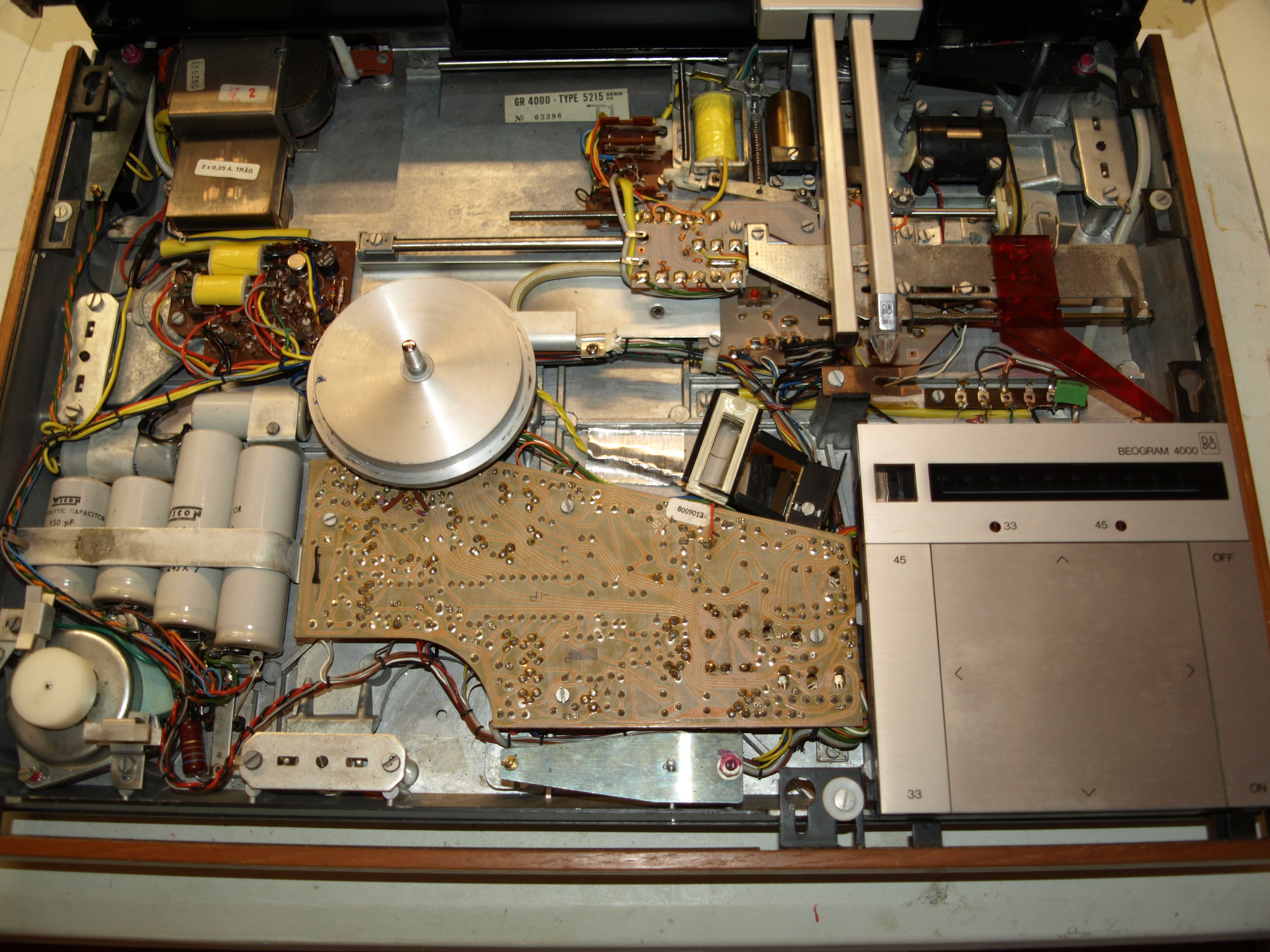
Overall the unit looks in good shape mechanically, and mostly cosmetically too.A test run will determine if there are any issues functionally..hcraig244SILVER MemberThe BG4000 looks in very good condition internally with no signs of previous repairs…always a good sign
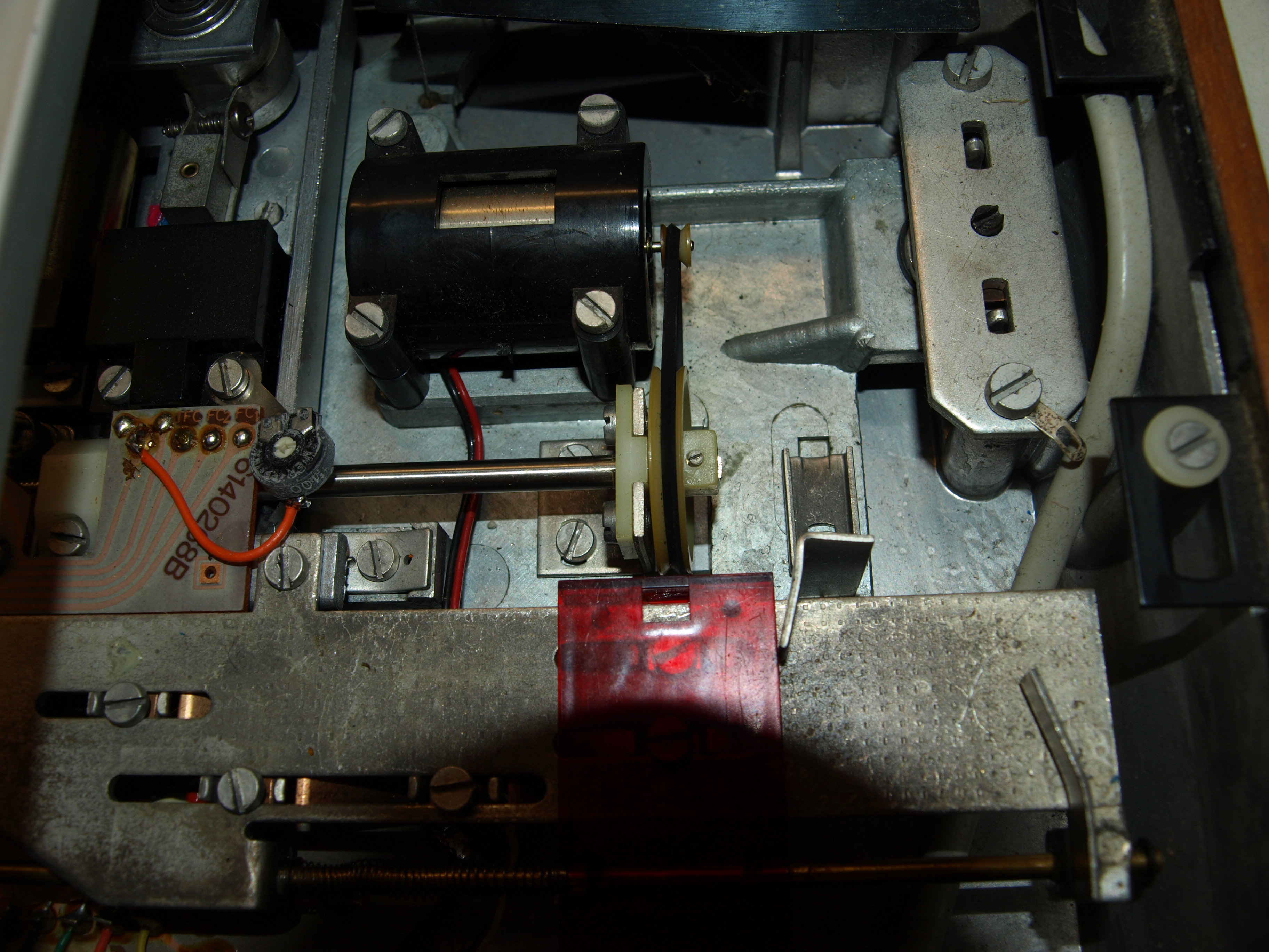
not sure about the quality of that image, but all looks well inside
Carriage drive belt is a bit out of alignment, not a problem.22 April 2026 at 09:53 in reply to: Looking for a replacement 10k log volume slider for a Beomaster 4400 #123350hcraig244SILVER MemberJust had a look in my cannibalised BM4000 and it there is a volume slider still in there, looking at the manuals in here it looks like the 4000 slider is 20k and not 10k……however the manual for the 4400 also shows the slider to be 2ok…..i could desolder it and send it to you at cost if you can confirm your requirements?
Craig
hcraig244SILVER MemberDo you have an oscilloscope and a signal generator? I find those two pieces very useful when trouble shooting…..injecting a known signal and tracing it through would bring you to the offending component
Craig
hcraig244SILVER MemberNew one on me…..not came across this before, does sound like a overheating issue….possibly breakdown of the compound applied to the output transistors on the offending channel not providing a good transfer of heat to the main heatsink? I will look forward to the conclusion of this one ;¬)
Craig
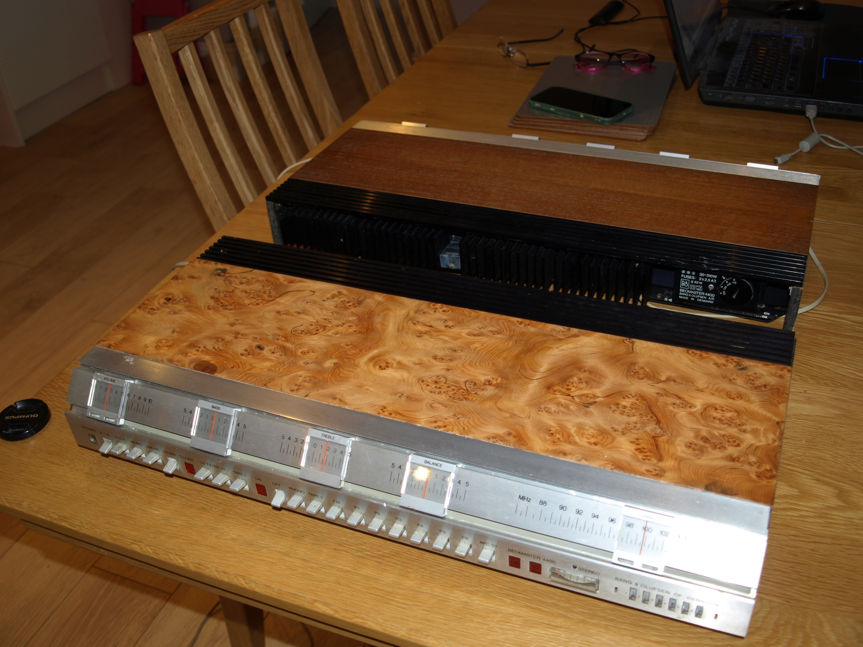
19 February 2026 at 06:40 in reply to: Query about 4400 top cover – grille exposes internals – is this correct? #74045hcraig244SILVER MemberAhh……well, thereby hangs a tale….when I was in the “4400” phase of my addiction I would buy any lost cause that appeared on ebay. I got a lot of pleasure from the repair and restoration of these units and chronicling the progress in the workbench forum of the old site, always received a huge amount of support and advice from the other members. The unit above came to me totally trashed and was described as “requires attention” which made me smile. The electronic repairs to the unit went well but the case ends and top where beyond reasonable repair and had to be completely rebuilt, never having attempted such work I decided to use a “ash burlwood” veneer on top of plywood…..it’s not a perfect finish but I like it. As a result, and unlike most of the others I acquired at that time, I’ve kept it…..
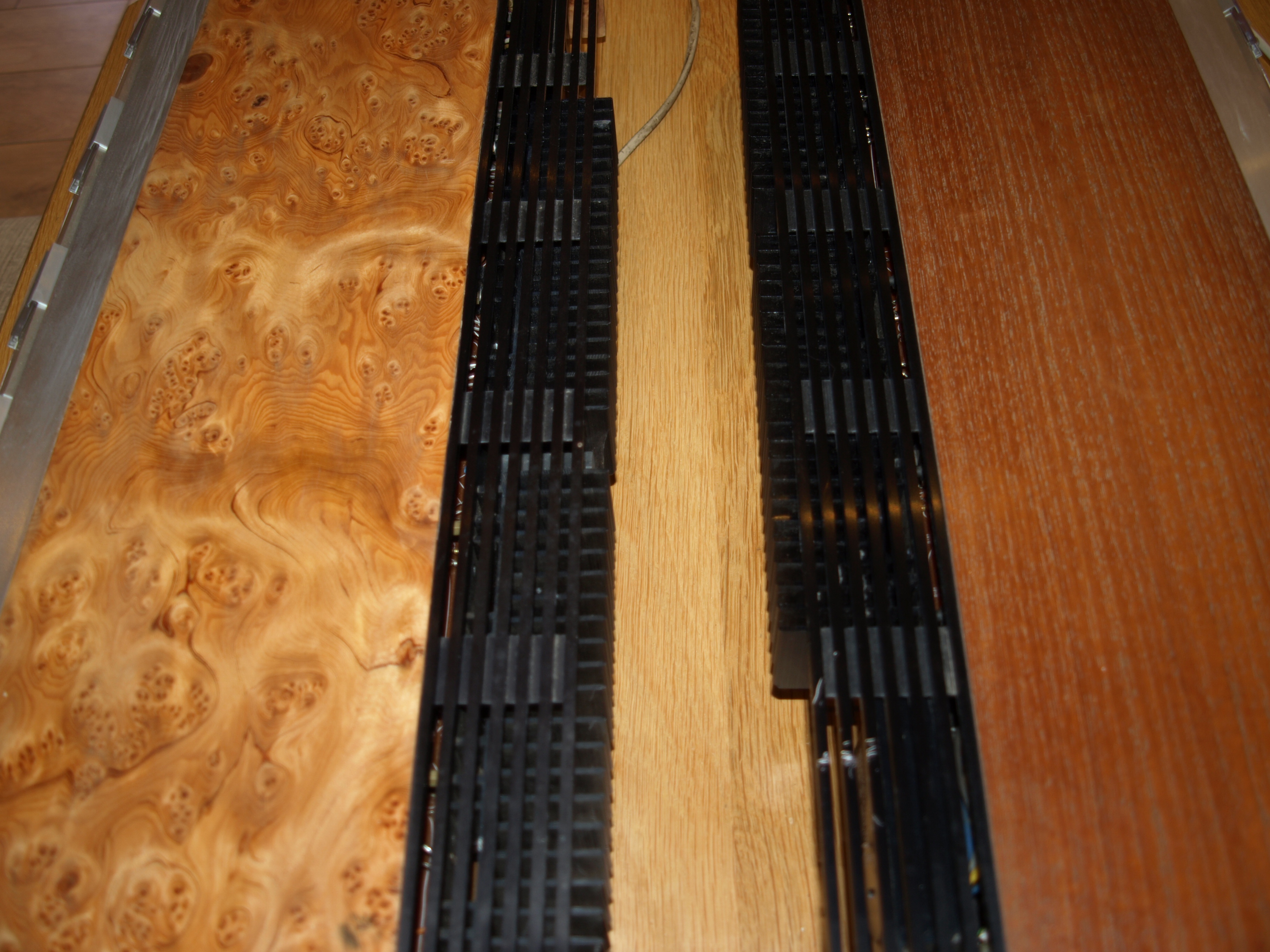
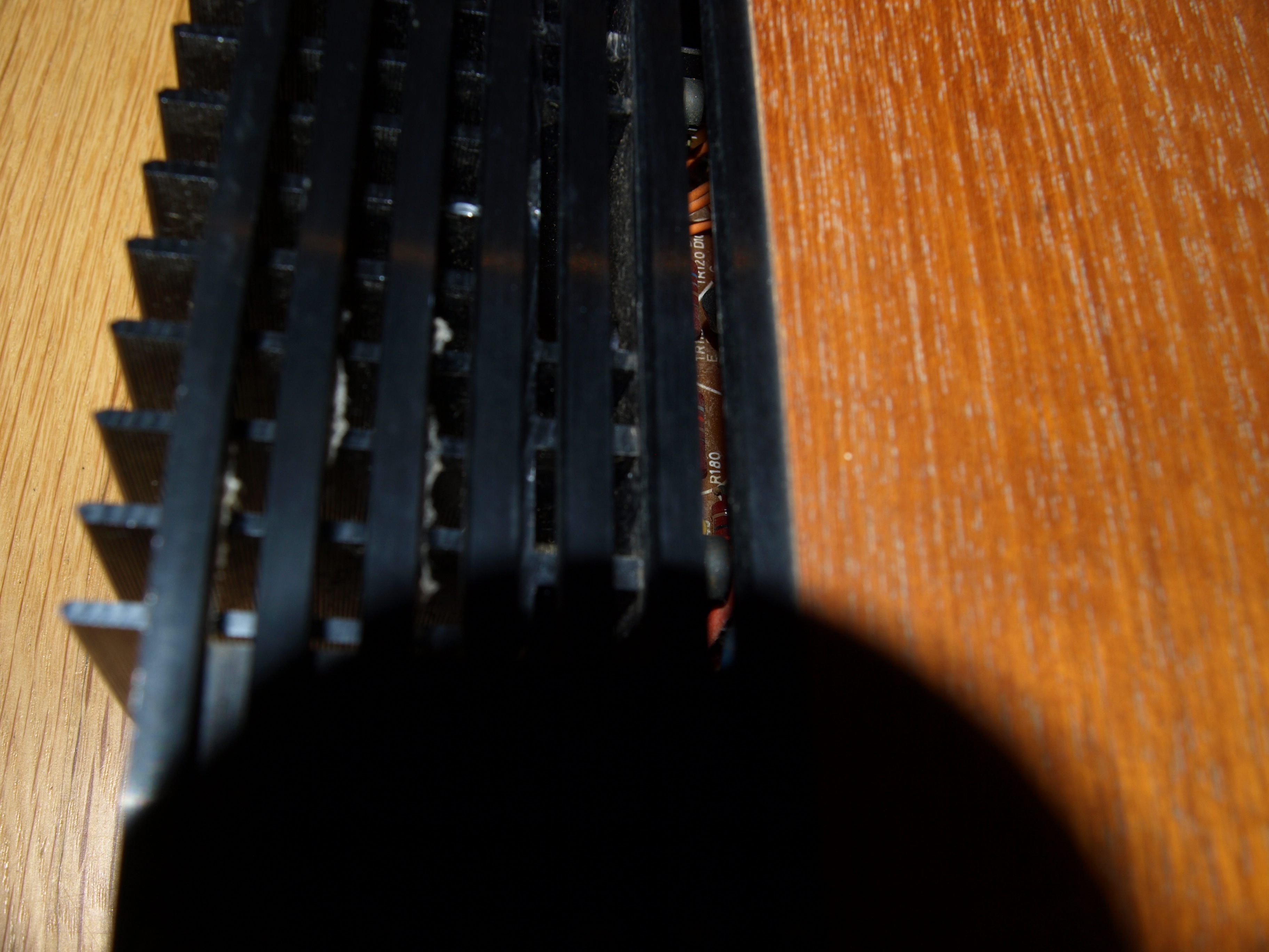
17 February 2026 at 10:44 in reply to: Query about 4400 top cover – grille exposes internals – is this correct? #73917hcraig244SILVER MemberIve still got a couple of these, please don’t ask me why two, and as can be seen both leave ventilation space beyond the cooling fins and into the power amp section….so I would say yours is normal ;¬)
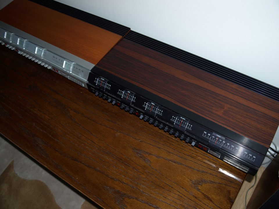
21 January 2026 at 08:44 in reply to: About to start my 2nd Beomaster 4400 restoration – need tuner restring advice #72749hcraig244SILVER MemberLooking in the manual posted it doesn’t detail the cord arrangements for the unit, if you require any pictures let me know and I will post some in here…..I read the description in the products section or the 4400 and the mention of the 4401 which was described as having almost mythical status….this is a picture I posted 10yrs ago showing a 4400 I was restoring back then alongside a 4401 which was loaned to me for a while for a comparison between the two by founder member Peter…..who still posts here occasionally.
Peter knows of two that exist…..this one and another which may have been sold to someone in Portugal as I recall.
16 January 2026 at 11:04 in reply to: Beomaster 3000-2 Type 2402 15V Power Supply Not Activating #72599hcraig244SILVER MemberUnfortunately powering up isn’t an option untill a proper investigation is carried out, check all fuses (im suspecting blown ones) and power up with the variac whilst measuring the voltages at this regulator…..sadly not got the time right now so not able to provide the information you require….sorry
Craig
-
This reply was modified 3 months, 2 weeks ago by
-
AuthorPosts