Forum Replies Created
-
AuthorPosts
-
 hcraig244SILVER Member
The lamps on the bottom will probably be easier to replace with the panel flat with the exception of the one on the far left which is mounted very close to the ribbon, these ribbons are very delicate and can be damaged easily….avoid if possible ;¬)
Attachments:
You must be logged in to view attached files.hcraig244SILVER Memberthe lamps are pushed into the holders and will only require soldering if a wire pops off during the replacement o a lamp, they can be quite tight after all these years so care is needed. the holders are pushed onto a tab that holds them in place…
Attachments:
You must be logged in to view attached files.hcraig244SILVER MemberThis is how they look when powered up….
Attachments:
You must be logged in to view attached files.hcraig244SILVER MemberThe lamp holders are located as shown here….
Attachments:
You must be logged in to view attached files.hcraig244SILVER MemberOk…..so you have got this far
Attachments:
You must be logged in to view attached files.hcraig244SILVER MemberExcellent…..these amplifiers are getting rather rare these days and need to be looked after, amazing pieces of engineering…..
craig
hcraig244SILVER MemberJust had a look in the manual myself and your correct it doesn’t detail the disassembly, I thought it did…..not to worry, is the amplifier fully functional right now apart from the lamps? It’s good to know that anything that stops working after you do anything in there is a result of what you have done which often makes it easier to correct 👍
hcraig244SILVER MemberOk
you will need to lift the indicator ribbon display section up into the vertical position to access the lamps….2 screws as I recall, these lamps are connected in three series loops I think…so if one goes down you loose 2 or 3 lamps….its been a couple of years since I changed any. As a silver member you can access the service manual for this machine under products in here, this details how to open it up…..unfortunately im windsurfing off the coast of Greece until Sunday….if no one chips in with more help I will open a machine up and send some pictures to guide you next Monday when I return to the UK
Craig
hcraig244SILVER MemberHi
Are you changing out all the lamps on the machine or just those that have failed? Some lamps are fitted into an enclosed plastic compartment, others are not. You will need to open the unit up to access all lamps…..check out the service manual available here for a better idea, be sure to replace the lamps according to the description provided by the supplier, the current ratings differ from location to location…….enjoy 👍
hcraig244SILVER MemberGo for it……. I wouldn’t buy one that was fully operational, the repair and restoration process is, for me, a large part of the pleasure. These decks where built with the possibility of repair in mind unlike the rubbish available on the market today….there are one or two more positives you can add to your list
- A stylus is fitted which suggests the tone arm connection tab, which the stylus snaps onto, hasn’t been damaged….lot of work and expense repairing it using the beolovers laser printed parts (which are very good it has to be said).
- The carriage drive motor and its associated forward/reverse circuitry is functional.
- The multivibrator on/off circuit is working as are the reed relays which switch the 20vdc and 6vdc supplys on……these can be problematic but are repairable.
I didnt hear the solenoid energise when the tone arm was requested to drop automatically or manually…..not a massive problem and could be down to poor lubrication on the tone arm lowering mechanism….easy fix if the solenoid energises on request.
Does the platter drive motor run? i’m assuming you’ve looked inside to check the drive belt?
A lot of problems with these decks can be traced to the control switches sticking open or closed therefore out of sequence, this will play havoc with the logic board operation, components will fail of course and some may need replacing as you progress through what can at times be a frustrating journey but provided you have the time and a few pieces of test equipment it can be very rewarding…..it can get expensive if you choose to install the many laser printed parts available but these are mostly optional.
Enjoy Craig
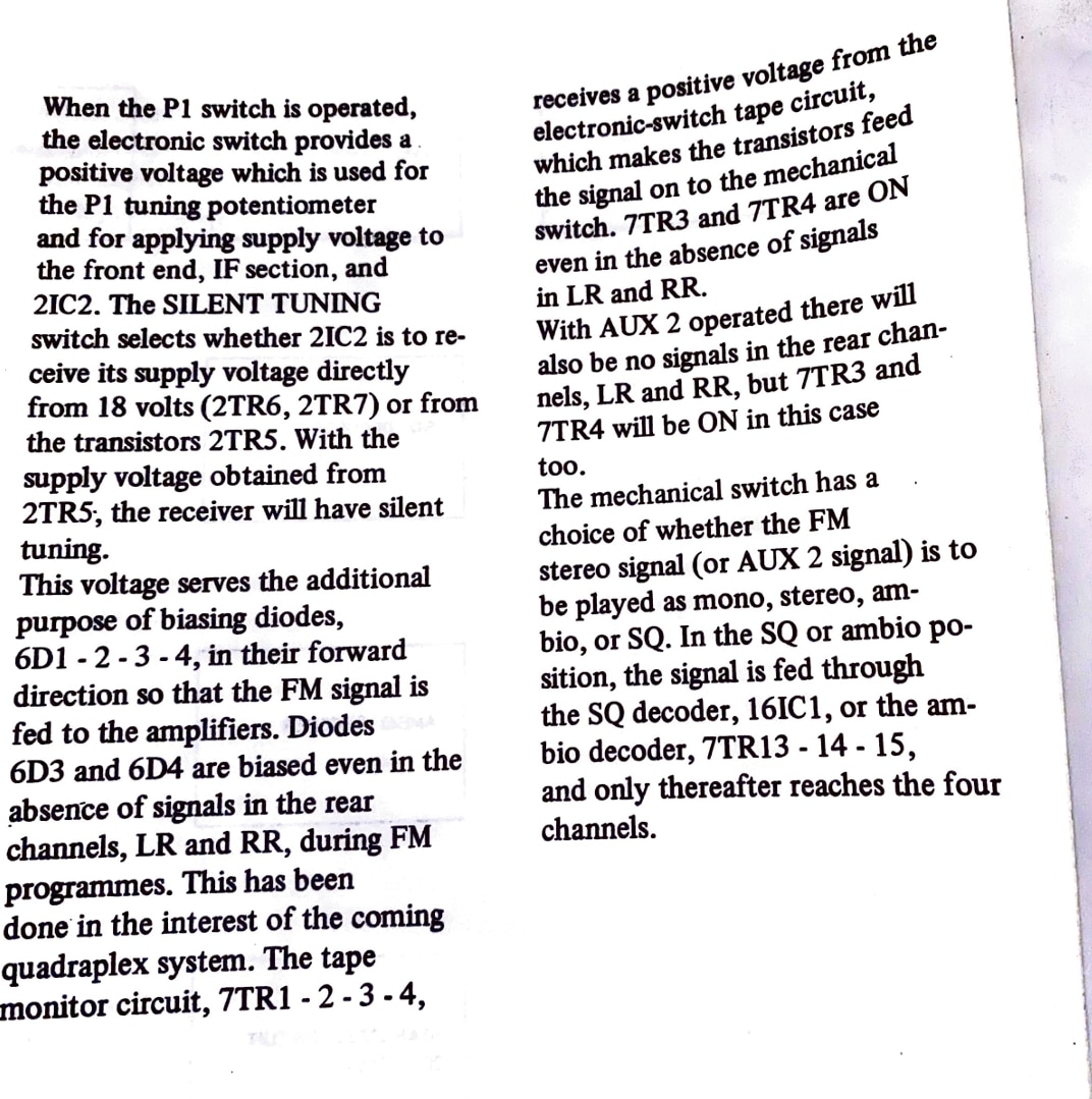
hcraig244SILVER MemberI’m guessing you have these from the circuit diagram you have posted….however I cant find that schematic in my manual….which is a little odd, all the same its a good place to look…..I checked the operation of both of my 6000 units and one is working perfectly and the other has an issue with the drive motors for the volume/bass/treble and balance potentiometers are not driving, i suspect the common drive belt but will have a look inside….if you need any measurements while im in there let me know….
hcraig244SILVER Member hcraig244SILVER Member
Not great image i know but i think this is where you could make a start
hcraig244SILVER MemberCheck all the black wires that run all over the machine, common negative, these wires are for some reason, best known only to the B&O design team, single strand wires and break easily…they dont solder too well either…i have had several issues with the point in the chassis where a whole bunch of these come together….take a look ;¬)
Craig
hcraig244SILVER MemberWhile axial resistors and inductors share a similar axial lead style, they are distinct components. Resistors limit current flow, while inductors oppose changes in current and store energy in a magnetic field.
my first experience with B&O equipment stemmed from a friend purchasing a Beomaster 2000 amp way back in the early 70’s…..i fell in love with it even though, as a poorly paid instrument artificer apprentice, it was way beyond my financial means. Roll the years on forty or so years and I also spotted a BM3000 on ebay for a ridiculously low price with a failed left channel…..how hard can a fix be I thought to myself? That was the beginning of a long and entertaining journey into vintage B&O equipment repair/restoration.
The BM3000 turned out to be a bit of a failure but I learned a lot during the experience, largely if not entirely from the input of the member on this site…..lots of members posted in what was then the workbench room….there was always some restoration/repair going on and the advice and support was exceptional…..those members are still here by the way….additionally B&O equipment was more widely available then and at much more affordable prices…..don’t know what happened but prices suddenly rocketed.
My advice, if your serious about this is join as a silver member and get access to the workshop manuals and circuit diagrams, identify the failed components and start to post pictures and measurements in here and people will start to input advice and guidance, they wont be able to resist…… be prepared for some initial disappointments and frustrations, you will need some test equipment and basic soldering skills…….but I feel given your desire to emulate your late grandfather you may enjoy, dont buy any components from ebay without first seeking advice in here……lots of fake transistors out there!
Craig
hcraig244SILVER MemberThats fine…
Would i be right to say that this is only one channel that is smoked and the other is still OK, I’m suspecting the output transistor has failed. Without extensive testing its hard to say for sure….the output transistors are Darlington Pairs and you would need to remove them as a start and test them…if blown they will need replacing along with the burned resistors you can see…also the power transistors normally fail due to something else failing first, that thing will need finding.
Looking at your post you dont have much experience on this sort of thing, as a silver member you can access the manuals in here to help you get an idea of whats ahead of you….
Craig
hcraig244SILVER MemberHi
Is this a Beomaster 3000…..if so at first glance it looks like a possible power transistor short could be responsible
hcraig244SILVER MemberThat will need to be quite a long weekend…..
hcraig244SILVER MemberPeter
You gave it to me several years ago for replacing the 33/45 rpm relay in your BG6000….or was it your BG4001 (with the black facia) i’m taking good care of it 😁
hcraig244SILVER MemberIt doesn’t address your question around item no 6 on the above procedure, which I cant either…..I note that Rudi deftly avoids that final step also ;¬)
Craig
-
AuthorPosts