Forum Replies Created
-
AuthorPosts
-
 hcraig244SILVER Member
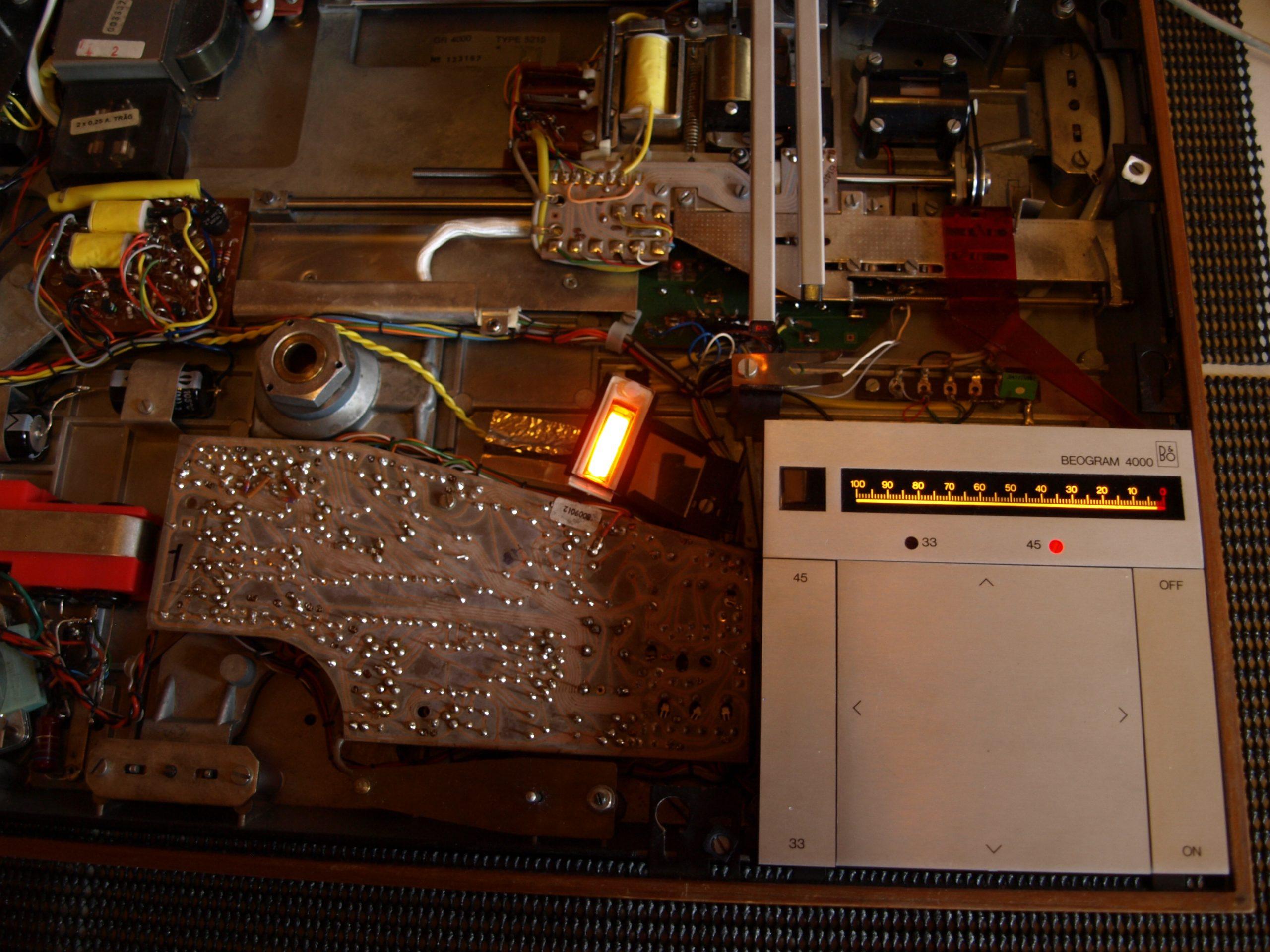
Hit Start and the neon lamp came on, always a good start….the 45rpm lamp also lit up and the main motor started to revolve….scale lamps also illuminated…all good stuff, however the solenoid energised straight away and the tracking motor sat motionless….a small push inboard did nothing….a small push outboard momentarily powered the tracking motor, the carriage didnt move as the belt to the pully was just slipping too much to get any traction.
So……quite a bit to sort out, I suppose the main good thing is that all the vital components, transformer/motors/solenoid and I did notice the detector arm lamp was lit/ are all healthy…they just seem to have “lost there marbles”.
I will start by examining the slider switches as they often seem to be behind a lot of issues with these decks…..as always comments and advice is welcome ;¬)
 hcraig244SILVER Member
Put the PCB back and got the variac out…….with the meter in series slowly powered up, the multivibrator circuit clicked on and there was no smoke or crackle of unhappy components..current draw was around 20ma…
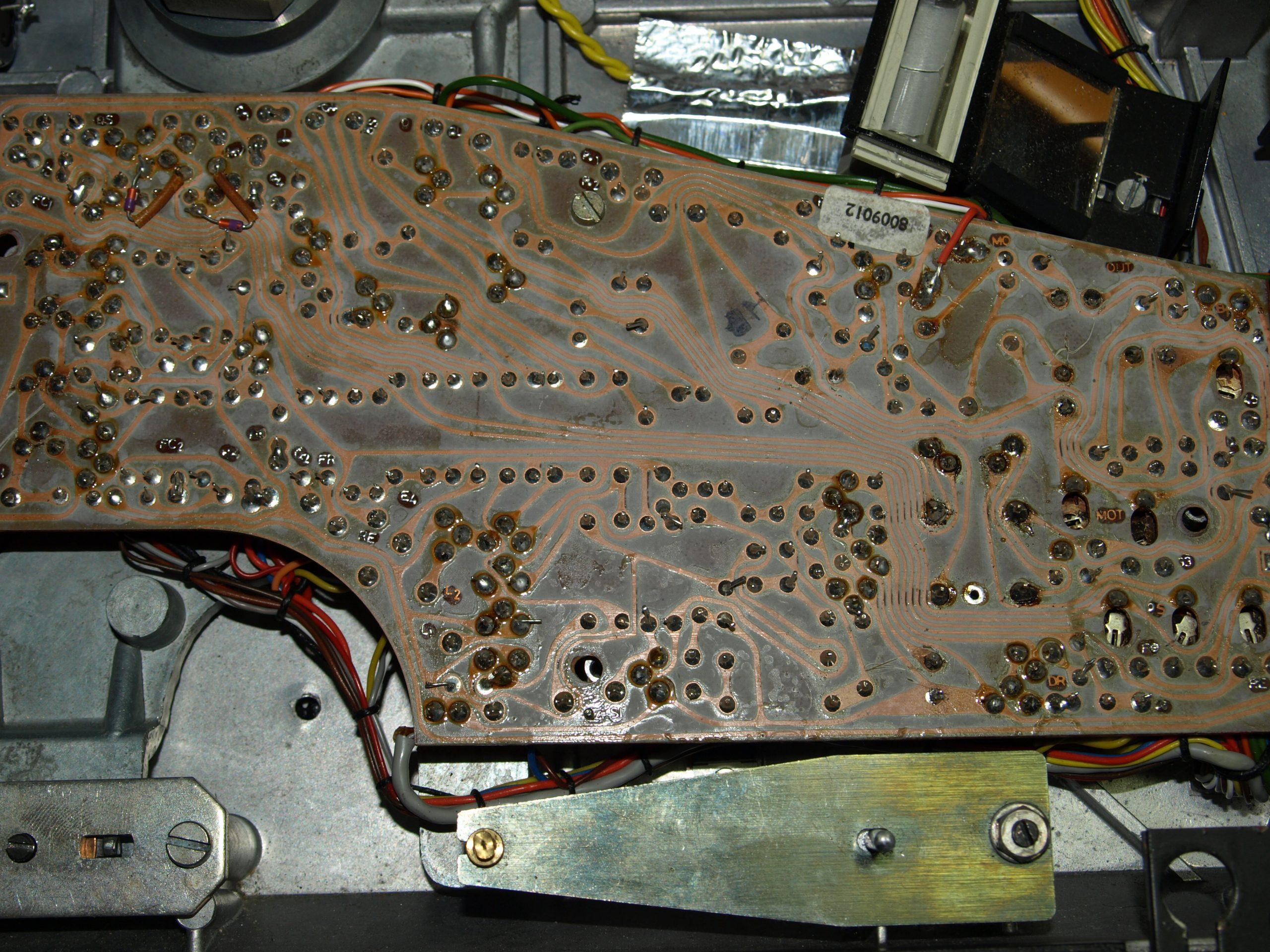
hcraig244SILVER MemberQuick look under shows signs of activity….looks like 1TR29 and 1TR30 have been replaced with something else…also the speed control relay has been replaced….
hcraig244SILVER MemberIts doubtful I would have missed the absence of said screws so im suspecting a third party involvement somewhere…..
hcraig244SILVER MemberOk…..opened up and a visual inspection prior to power on reveals only one screw holding the main PCB in place….not a very encouraging start.
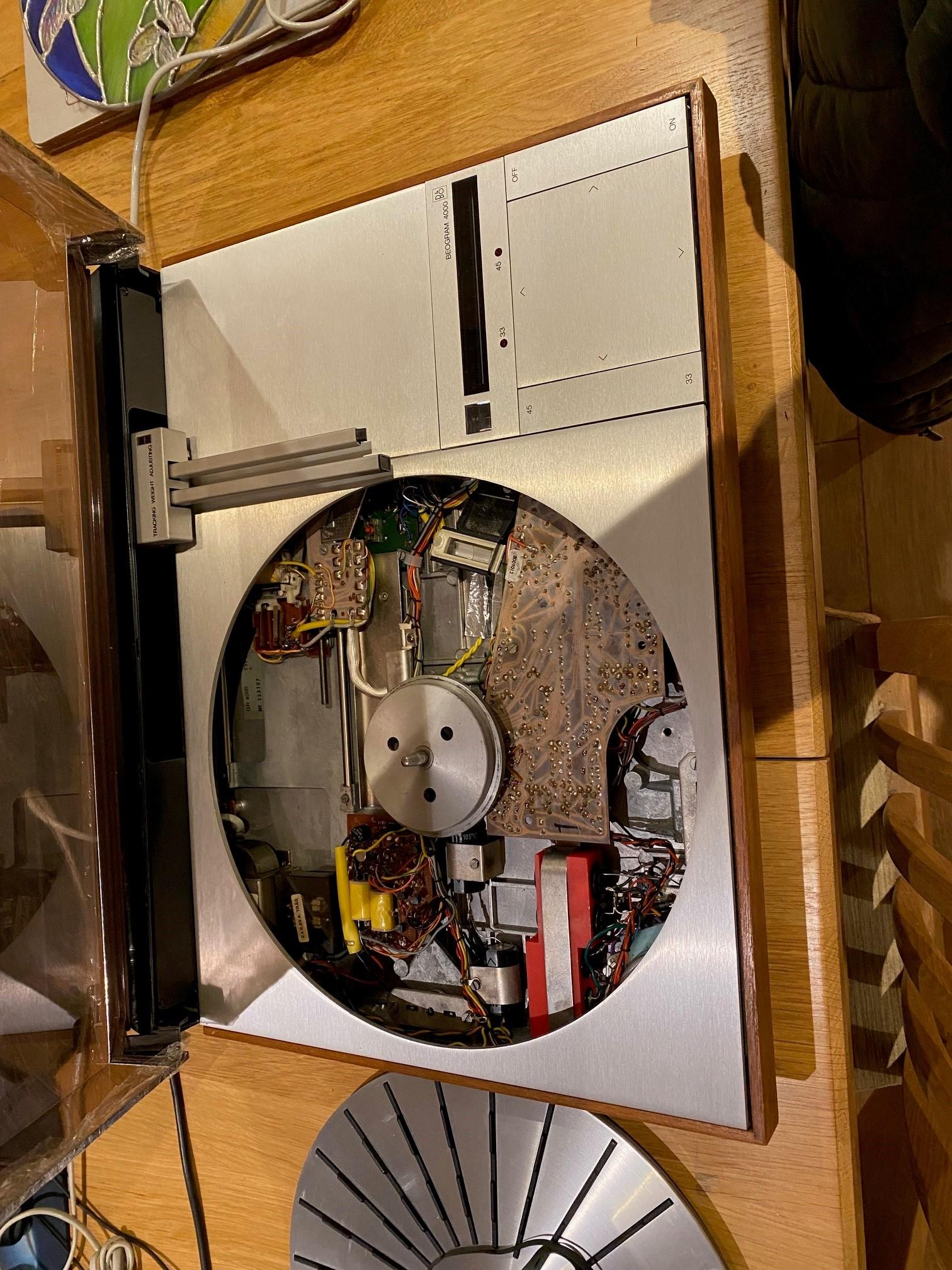
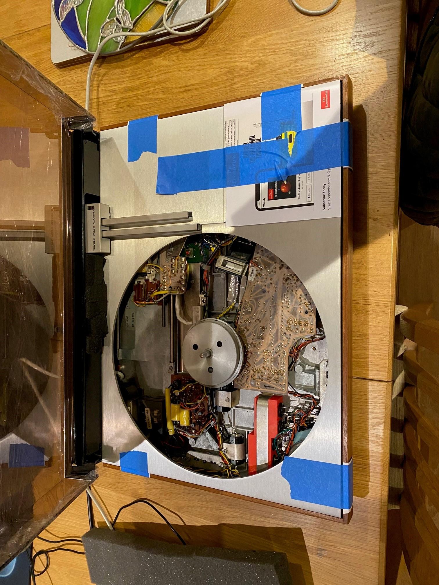
hcraig244SILVER MemberBeen here before as can be seen from the Rudi patented laser printed capacitor bracket, and the ne 6v & 24v power supply smoothing capacitors….cant quite remember what else I did in here but I suspect it may have been a replacement of the 24v regulator OTR1….It comes with the description of “misbehaving” in as much as the tone arm is driving inboard and not returning to the stop position when required….I will have a look.
 hcraig244SILVER Member
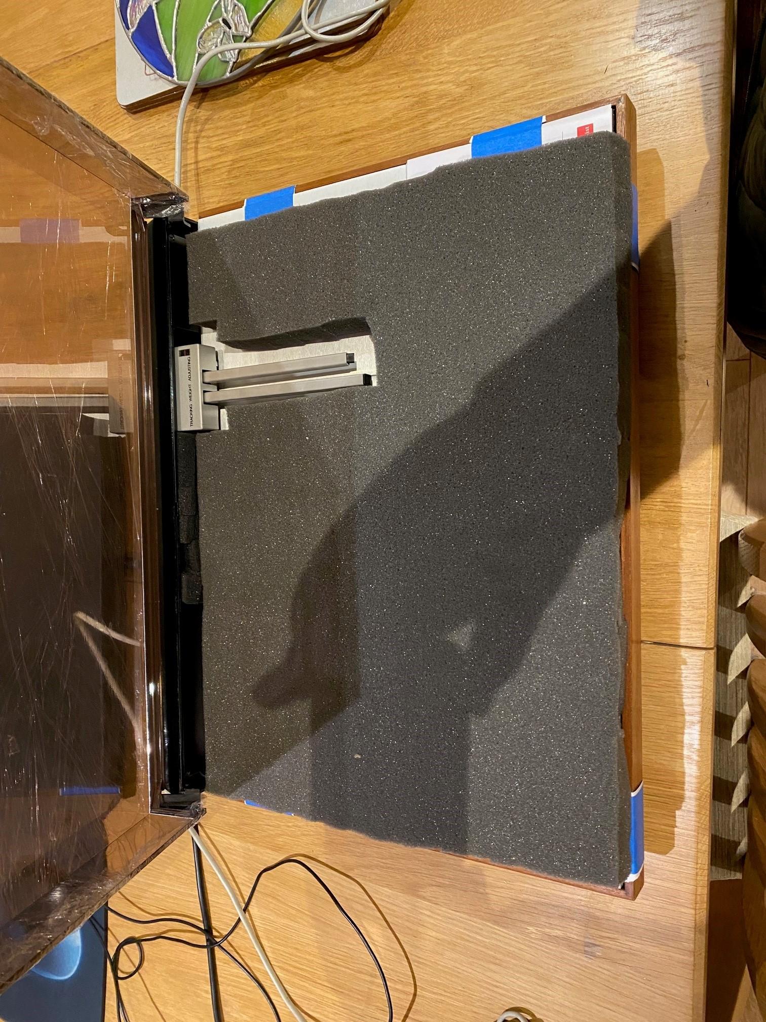
Well secured and packed…..platter was packed separately and stowed away under the Beogram in foam and cardboard
hcraig244SILVER MemberLifted out …..
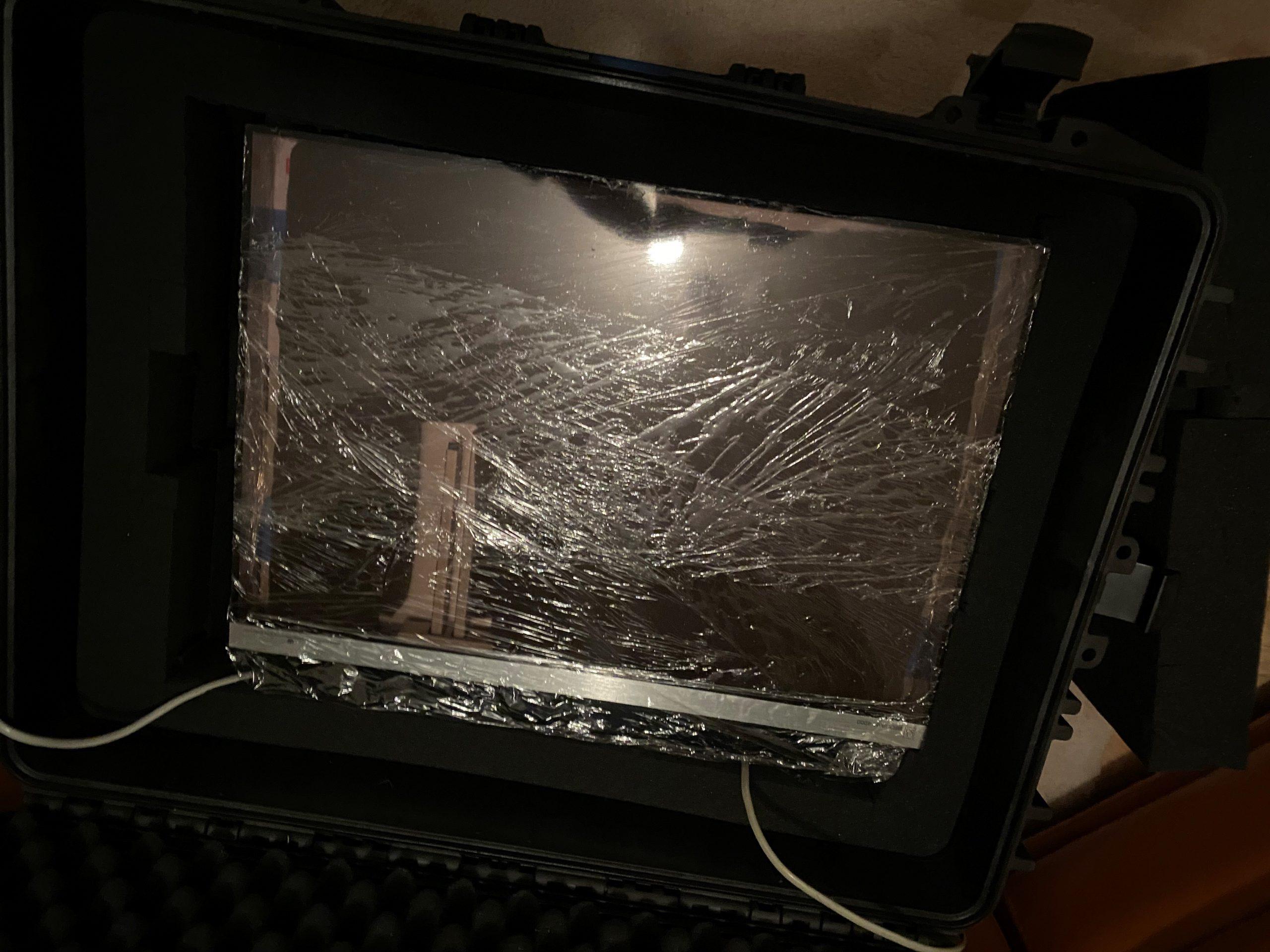
hcraig244SILVER MemberNot a particularly good image but does show the extent of the protection the chest provides for these delicate machines…given the degree of abuse they would suffer at the hands of almost all delivery companies
hcraig244SILVER MemberAnd inside the chest was a heavily padded BG4000….
hcraig244SILVER Membermust be these two fellows………
hcraig244SILVER MemberFrom your pic I can see the tone arm connector which accepts the cartridge is ruined…..this can be replaced with a lazer printed component available from Rudi the Beolover. This is a quite involved process requiring some very tricky soldering and also some time to achieve, the absence of light from the detector arm may be nothing more than a burned out lamp, also requiring some soldering skills…..these are not tasks to be undertaken by anyone unsure of said abilities…..and if one can find a repair shop willing to take it on, not many will due to the time consuming process, they will charge you a fortune. I have a B&O shop close to me who advised me they charge £150 just to look at a BG4000…..needless to say any repairs on my kit is carried out by myself ;¬)
Tim Jarman is well respected in this forum, though I have never met him, I’m sure he would be more than capable of giving you some guidance.
Craig
hcraig244SILVER MemberLooks to me like the “upgrade” in question doesn’t cover the more complicated BG4000…..even though the end result is identified as such
hcraig244SILVER MemberAnd post some pics….always useful ?
hcraig244SILVER MemberJust had a thought, is this the 6000 quad amp, unfortunately I have assumed it is ?
hcraig244SILVER MemberLove these amps…so over engineered it’s untrue, you should consider replacing all the capacitors as a matter of course, however it’s a good idea to resolve the problem you have first so you know your not introducing additional issues as you go along.
you could start by looking at replacing the four output capacitors first, I have found these caused similar problems to the one your having…..and as you should replace them anyway it’s a good place to start, check out my posts in the archives, I’ve done one or two and they may help you out….enjoy ?hcraig244SILVER MemberMartin aka Dillen will sell you a complete set of capacitors and lamps for this unit, not sure what he charges these days so you need to send him a post…….however replacing capacitors may be just the start………first thing would be to determine if it actually works prior to replacing anything, most problems can be resolved without spending a fortune and these amplifiers are well worth restoring
Craig
hcraig244SILVER Memberthis is the adjustment for a BG4000……..
hcraig244SILVER MemberWell……thanks for clearing that up ;¬)
hcraig244SILVER MemberOk……so what did you replace? I’m guessing capacitors and maybe trimmers, double check the polarities of the caps you changed, it’s easy to get one in the wrong way around
-
AuthorPosts