Forum Replies Created
-
AuthorPosts
-
Dillen
ModeratorThe center spindle for the cam wheel can be lubricated, but all the small “rattling” arms and levers on the cam wheel should run clean and dry.
They must NOT be lubricated, or things won’t work.Martin
Dillen
ModeratorIt’s mask programmed by/for B&O.
But these rarely fail.
What are the symptoms?Martin
Dillen
ModeratorI have seen cases where Beocord 9000 rec. cal ends as Metal tape detected with a CrO2 tape inserted,
if the Beocords bottom plate is not fitted, so correct assembly is one important thing.Martin
Dillen
Moderator- Kit here.
- Yes. And it must be done in an ESD-safe environment.
- The service manual will tell you how.
Martin
Dillen
ModeratorNo. The Marantz post was spam.
Martin
22 December 2023 at 12:10 in reply to: Midrange speakers on my Penta – If one speaker is dead do they all not work? #51456Dillen
ModeratorAn open-circuit midrange will see all four going silent.
I have one, refoamed and ready.
PM me if you need.Martin
Dillen
ModeratorAdjustments can be done through holes in the bottom plate. Refer to the user or service manual.
But trimmers and/or capacitors may be bad.
A service kit is available.Martin
Dillen
ModeratorThe laser is not specific to B&O.
– But is that a carpet? Get it away from that!
These are static sensitive devices, – (VERY!) easily damaged by static electricity.
Wear an ESD protective wrist band and work on an ESD field mat as a minimum.And of course the shop will accept a return, but if you bought something by mistake they
will most likely (and fairly) ask you to pay the return postage and that could, depending on your location, not be worth it.Martin
Dillen
ModeratorA bit difficult to measure.
As long as one end of the capacitor is not connected to anything, only the voltage at the other end is known.
And noone knows what it will be connected to in the future.A foil cap would be a good solution as well – but completely out of proportions quality-wise.
Looking at the rest of the construction there will be other limitations playing in long before any difference from electrolytics to foil caps come into view.
This Beomaster is not an audiophile unit in any way, – never will be and never was intended to be.Martin
Dillen
ModeratorLook at the series of components; DIN socket, resistor, capacitor and transistor.
If the resistor is nearest TR100 (and the capacitor is nearest the DIN socket), the caps positive pin should go towards the resistor.
If the capacitor is nearest TR100 (and the resistor is nearest the DIN socket), the caps negative pin should go towards the resistor.Martin
Dillen
ModeratorThe series of capacitor and resistor can be in either order.
One end of the capacitor carries a known DC level ~ the base voltage of the first transistor.
Seeing as this is an input, we don’t know the level of any DC content of the incoming signal.
It’s a general handrule to make the positive lead face inwards.This also goes for line-level outputs. Positive inwards.
So when coupling an input to an output, it will be negative pin facing negative pin = bipolar capacitance.Martin
Dillen
ModeratorC110 (2,2uF series coupling capacitor for phono right channel input) should have
positive pin towards TR100/R111.Martin
Dillen
ModeratorI wondering what weight range would be good for a Record Weight for my 4002.
None!
Use no record weights, antistatic mats or other nasties with any Beogram.
If your record is warped, put it under press somewhere else (not on a Beogram) or discard and replace it.Martin
Dillen
ModeratorDillen
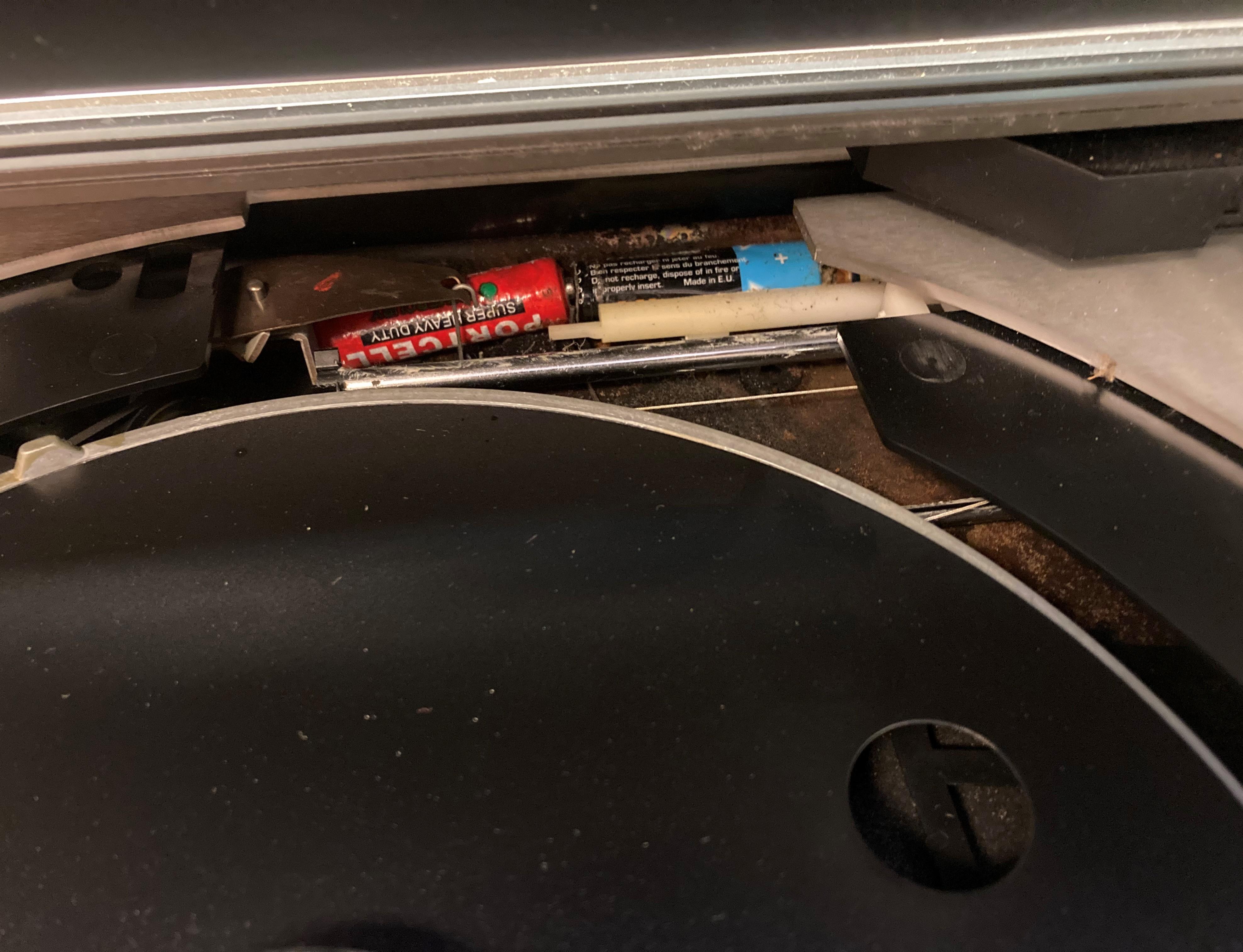
ModeratorIt’s not uncommon to find spare cartridges, or parts thereof, inside Beograms.
Same goes for center pucks, stylus guards and needle brushes.
I have also found lots of coins, keys, jewelry, LEGO bricks etc.
Under the dust cover seems to be a “safe” place to store small items.
When the Beogram is later moved, the things slide around and fall into the innards.In the larger 1930s to 1960s valve-based radios you could, and still can, sometimes find savings and love letters.
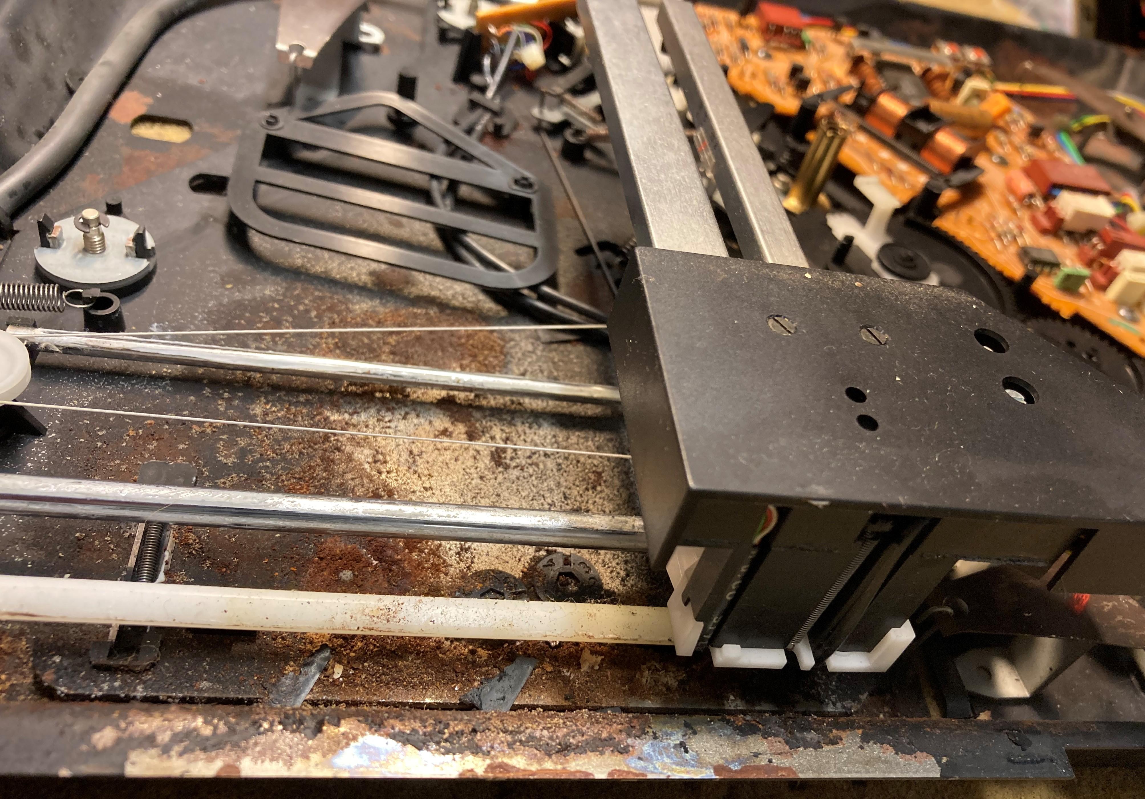
These radios were often fairly large cabinets with room to spare, – a good and safe place to keep secrets from the wife, as she was not likely to ever go in there.Here batteries in a Beogram 5500, arrived here for repairs because the carriage was blocked:
Close, but no cigar.
Martin
Dillen
ModeratorYou can see it here:
https://beolover.blogspot.com/2020/03/beomaster-4400-type-2419-investigating.htmlHalf way down the page.
Martin
Dillen
ModeratorLay the large black hinge bracket (the rear vertical plate) flat on the table with its backside down. Put it on a thin piece of cloth or similar to prevent scratches and scuff marks.
Place the three small shiny friction plates in place in the hinge bracket, so that they sit aligned with where the three holders will be (photo).
From little marks they have left, you can usually see where they sat previously, and you can glue them in if you find them difficult to control.Put the dustcover in place in the bracket, also lying flat on the table (in what would correspond to fully open position if upright) and fit the spring to the hinge bracket at the center with a holder, a screw and a washer. Don’t mind the springs ends at this point – just let them flap around as they please until the center holder has been fitted.
The spring has small round ends, that needs to run in the grooves at the ends of the dustcover, so make sure the spring is the right way up, or it will run with the sharp pointed ends in the groove and wear the grooves out in no time.Then grab one end of the spring with pliers, twist it to upright position and set the springs length down in the groove in the hinge plate (some hinge plates have small tags it needs to go around and between) and set it into the groove in the dustcover.
Often the spring will be able to sit by itself like this.
Put a black plastic holder in place, hold it with a finger or two while you lift up the whole assy and mount the screw and washer from the other side. Alternatively, keep it flat and slide it out over the edge of a table, just enough to fit the screw and washer from below.
Same job at the other end.
Takes a little practice but it’s a 2-minute job when you know how.The above instructions for assembly of the dust cover, spring etc. is valid for the following
Bang & Olufsen models:Beogram 1100
Beogram 1102
Beogram 1500 (Type 57xx only)
Beogram 1600
Beogram 1602
Beogram 1700
Beogram 1900
Beogram 1902
Beogram 2200
Beogram 2202
Beogram 2400
Beogram 2402
Beogram 2404
Beogram 3400
Beogram 3404
Beogram 6000 (Type 57xx only)
Beogram RXThe square holders (friction brackets) are known to break.
New parts can be found here.Martin
Dillen
ModeratorThe motor runs all the time, when the Beocord is out of standby.
Martin
Dillen
ModeratorCould be the safety circuit kicking in. It kicks in if the motor is loaded abnormally.
This can happen, if something has seized or running rough in the mech. or if the belts are not correct (too thick or too tight).
– Ebay belts?Martin
Dillen
ModeratorThat depends on the territory version, as some have polarized mains plugs and capacitive
decoupling to chassis in accordance with local regulations.If your mains plug can be plugged into the wall outlet any side up, it’s safe to swap the leads.
If you have a three-prong mains plug that cannot be reversed, or your mains plug for
some other reason can only be plugged in one way, you should keep the mains leads in their original positions.Martin
-
AuthorPosts


