






Home › Forums › Product Discussion & Questions › BeoGram › Beogram 4000 and also BG8002
Tagged: r10
- This topic has 116 replies, 3 voices, and was last updated 1 month, 1 week ago by
 hcraig244.

-
AuthorPosts
-
27 June 2026 at 14:41 #124229
 hcraig244SILVER Member
following a thorough examination I failed to find a break, reflowed the solder connections on all four connection points and now the solenoid energises and the tone arm drops…..dont know which solder joint was responsible 😐
27 June 2026 at 14:49 #124230hcraig244SILVER MemberPut everything back into service mode and with a cartridge fitted and a disc on the platter powered it up. The tone arm dropped at the correct place….result, however the tone arm isn’t traveling inward as the stylus moves inward, I’m hoping it’s nothing more that a slipping belt….will have to put everything back into service position and take a look…..oh and the buzz is ever present
Attachments:
You must be logged in to view attached files.27 June 2026 at 17:13 #124239The click you are hearing is the muting relay and independent of the solenoid.
28 June 2026 at 10:06 #124248hcraig244SILVER MemberMark
Thank you for that information, we now know the muting relay coil is good, I’m going to take a closer look at the tone arm drive motor to ensure all is good mechanically, It could be the belt is slipping but I’m not sure….visually it looked good…if the deck has been dormant for some years it could be a lubrication issue also….following that I will measure the voltage to the motor, it should be possible to check the motor with the drive belt removed to check its response independantly?
Craig
28 June 2026 at 15:08 #124253hcraig244SILVER MemberOk
Back in the service position, motor drive belt looks in good shape with no signs of slipping, nice and taught…no cartridge fitted and play pressed….carriage moves to the drop area, solenoid engages and the tone arm drops….carriage starts to move inward in a quite determined manner…tried stopping ad starting a couple of times and the same thing occurs my view is that it should wait until the aperture allows more light onto the photo sensor and move to decrease said light…..to confirm this I opened up the fully functional deck and carried out the same check…and as expected the tone arm dropped upon reaching the drop area and stayed stationary until I nudged it forward slightly and it moved inward very slowly, more slowly than the faulty unit.
Therefore my question to the forum (you really Mark) is should I carry out an aperture adjustment…and if so do I really need a testing record as per the service manual….or is it best to wait until I have replaced all old capacitors then check once more before making said adjustments
Best Regards Craig
Attachments:
You must be logged in to view attached files.28 June 2026 at 15:19 #124255Yes you should perform that adjustment and no you do not need a test record.
29 June 2026 at 08:09 #124272hcraig244SILVER MemberRight…adjustment made and now the carriage starts to move inward when the tone arm is nudged slightly inward…..however we’re not out of the woods yet, the carriage moves inward only when nudged but doesn’t do so in a sufficient number of steps…I read in one of Rudi’s blogs that the motor should turn partially every revolution of the platter, this platter is going around maybe 5 or six times before the motor turns to catch the carriage up and then it starts to turn to many times and the tone arm skates across the disc alarmingly…..it’s like the signal to stop the motor turning when the aperture should be closing isn’t happening…..I’m suspecting an alignment issue somewhere on the mechanism…..oh joy!
-
This reply was modified 3 months, 2 weeks ago by hcraig244.
29 June 2026 at 18:33 #124278hcraig244SILVER MemberOk….after almost an entire day chasing my tail in completing various adjustments to the pick up arm and the photo control aperture…..all of which where looking good until I fitted a cartridge and (with P4 plug removed to allow hand control) and tried to rotate the platter and view the drive motor revolutions….everything went to rat shit!….pick up arm skating around randomly…at this point I removed the cartridge and replaced it with the one I fitted to the working 8002….and everything settled down….now its looking good, which is more than can be said for the cartridge….on close inspection neither is in good shape, the functioning one seems to have a loose cantilever despite still funcioning. I think they can be re-tipped but I’m not sure….non the less I will now move onto the third and what is possibly the most challenging of the three.
-
This reply was modified 3 months, 2 weeks ago by hcraig244.
Attachments:
You must be logged in to view attached files.29 June 2026 at 19:15 #124282I’m glad to see you’ve got it working. our comment about every 5 revolutions is incorrect, According to B&O’s calibration procedure, the servo motor shutter should be adjusted to cause the servo motor to run every 2-3 revolutions.
The first picture is definitely a damaged diamond and will do damage to your records which is why you should be diagnosing and testing with a record you don’t care about.
-
This reply was modified 3 months, 2 weeks ago by
30 June 2026 at 16:10 #124307hcraig244SILVER MemberCheer Mark
I have now placed the 3rd and final BG8002 in service position and following a visual inspection of the carriage servo motor belt and confirme everything looked like it was sitting in the right place i pressed play….motor spun, screwed shaft rotated and the pick up arm moved inward for about an inch and stopped dead…I was able to return it back to the start position using >> button.
The platter turned and all lamps appeared to be functioning correctly, I repeated the above several times and got the same results….I’m suspecting the optical encoder as per one of Rudi’s blogs so will need to get the scope out and look for signals across R10 and R11 I should get the square wave outputs…….assuming all is well?
 1 July 2026 at 00:18 #124322
First, was the plater on when you tried this? If not, try it with? If that does not work, try pressing Stop instead of >>- what happens?
1 July 2026 at 07:43 #124327hcraig244SILVER MemberMark
This morning I have performed the same test with the platter in place….same results, pressing STOP instead of >> has no effect, the carriage remains stationary 2cm from its start point, the platter continues to rotate until I manually drive the carriage back to the start position upon which everything closes in the normal way.
Craig
1 July 2026 at 08:41 #124329hcraig244SILVER MemberFurther to the above I am measuring 1.24vdc at pin 7 of plug P2 (IR Diode power supply) which would indicate that the diode is fine…will hook up my scope and see if i’m getting the required pulse’s from the pins 4 & 6 of plug P2
1 July 2026 at 11:41 #124332hcraig244SILVER MemberWhen I measure the voltage at pins 4 and 6 of plug P2 and turn the encoder wheel by hand I measure between 14.3vdc and 0,7vdc suggesting that the photo diodes are functioning correctly…however the measurement at the input to uIC1 taken at R10 &R11 respectively only returns 0-2,9vdc as I rotate the encoder wheel by hand….I suspect this is low and should be nearer 0-5vdc?
Craig
1 July 2026 at 15:50 #124333hcraig244SILVER MemberRight……measured the voltage signals above at R10 & R11 on the Beogram that is functioning normally, drive belt removed to enable the encoder wheel to be turned by hand, and the voltages measured are the same…0-2.9vdc so its looking very like the encoder circuit is working fine?
Craig
2 July 2026 at 16:51 #124345hcraig244SILVER Memberis there a problem with the site today? can’t seem to post pictures?
-
This reply was modified 3 months, 2 weeks ago by hcraig244.
3 July 2026 at 10:50 #124367hcraig244SILVER MemberOk…..gone to full service position now!
Attachments:
You must be logged in to view attached files.3 July 2026 at 10:54 #124369hcraig244SILVER MemberAnd if I’m not mistaken someone has carried out a full recap too…
Attachments:
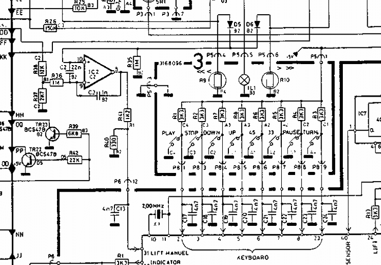
You must be logged in to view attached files.3 July 2026 at 11:42 #124372hcraig244SILVER MemberHappy with the encoder signals from the drive carriage im looking at the forward/Reverse Scanning Sensors (Control Panel LDRs)..
not the best image i know, existing wisdom tells that if the voltage goes high at either P5 pins 4 or 6 a high signal will be fed to I1C pin 31 thus disabling the pick up arm after approx 2cm travel…..just what I’m gettingAttachments:
You must be logged in to view attached files.3 July 2026 at 12:55 #124374hcraig244SILVER MemberRemoved the cover from the lightbox and with a meter checked continuity across the lamp….all good, checked the resistance of the LDR’s with the light from my desk lamp on and got the following readings…not the same but they should be ok?
Attachments:
You must be logged in to view attached files. -
This reply was modified 3 months, 2 weeks ago by
-
AuthorPosts


- You must be logged in to reply to this topic.