Forum Replies Created
-
AuthorPosts
-
 TKBRONZE Member
Thanks for the document, @pl212. You’ve probably seen the MCL’82 protocol document (attached) that I uploaded a few months back. It represents the final variant of MCL1 before the release of MCL2 (Datalink ’86). There was almost no documentation that I could find when I assembled this protocol document, which was created mostly by me spying on the messages being passed between a Beomaster 5000 and MCP 5000. There are still a few straggler messages whose meaning I have yet to fully decipher, which I hope to get to some day.
I recently acquired an original MCP, designed for use with the Beocenter 7700 (which I don’t yet have). Just based on the jumpers I see in the 2041 relay boxes, I’m thinking the MCP instruction set is unique to the 7700 – or at least the response messages will be – but I’d venture to guess there will be some overlap in the command set between the MCP and MCP 5000. Having just the MCP, I’ll be able to verify outbound commands for starters. If you happen to have a Beocenter 7700, perhaps you can add to the knowledge-base by providing the responses for the documentation.
I’m in Marin, so we’re close by each other, and can get together to compare notes over lunch, if you’re interested.
Attachments:
You must be logged in to view attached files.TKBRONZE MemberThere’s a nice project on GitHub called Beomote which is along similar lines to what you are looking to do, and might help get you started.
As to potential hurdles, if you are only looking to do one-way stateless with a URL callable interface (for example), your life will be much simpler. A 2-way application will need to remember some semblance of system “state”, and occasionally have to sync its internal state condition with whatever system its controlling. B&O provided a “status” query in the early 2-way protocols, which makes things a bit more manageable, but the entire “state” of the Beomaster is not queryable all at once, so you have to keep careful track of the sporadic incoming status messages to keep track of where things stand. Something to consider during design.
For fun, I’m working on a project I call BeoBabble which facilitates 2-way comms between the early pre-Masterlink units, and runs on an Arduino. I had to shelve it for a while as it was taking up a bunch of time, but I plan to dust if off in a few weeks time when things calm down. At some point I’ll add an IR interface, because it appears to be the same decode/encode pattern from what I can see, but that interface won’t be available for a while. I only mention it here because Beo4 is straight Datalink ’86 in it’s most basic form, which is one of the early protocols BeoBabble supports. If I can be of any assistance in that specific arena, I’m happy to help.
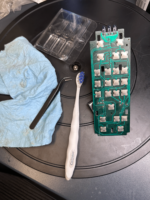
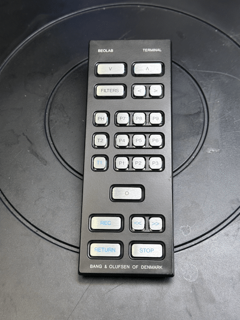
TKBRONZE MemberA Beolab Terminal that I bought for $50 had lost a battle with a glass of some sort of sticky cocktail. Half the buttons were non-responsive, so I took it apart and bathed the components in Iso. Luckily all the traces were undamaged and tested fine.

Everything looked and worked great after re-assembly.
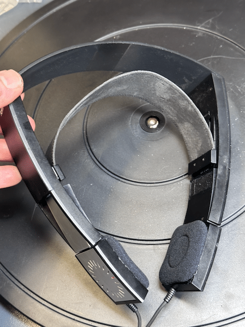
I still need to re-tape the button pad. The original is very much a one-time-use material. Does anyone have a “favorite tape-medium” they use for this purpose? I was just thinking clear or perhaps thin black packing tape would work fine, and provide a bit of protection.TKBRONZE MemberReceived a complimentary Form1 with another purchase, it the usual condition – without foam. After reading the archives on the issues everyone was having with the original foam, I bought a cheap set of Logitech 150 foam replacements for $10-for-2-sets, and affixed them with trim adhesive. Not ideal nor exact replacements, but serviceable given the time and effort I was willing to put into it. If someone ever has a better solution, I can always shave them off. Unit seems to work fine without the upper cushions, but then, I’m not overly concerned with comfort, fit and finish of this particular headset. Hopefully someone else can find this information useful to repair their sets without foam.
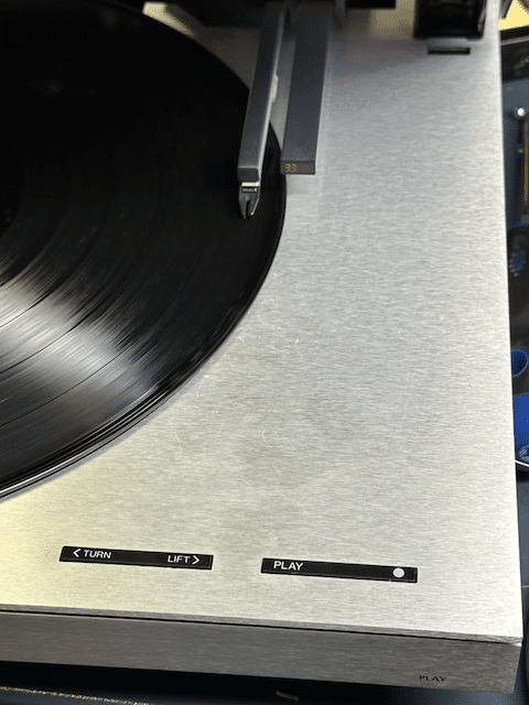
TKBRONZE MemberJust to document the needed changes to add discreet “Play/Off” function to an early Beogram, these are the steps.
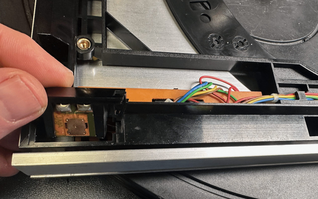
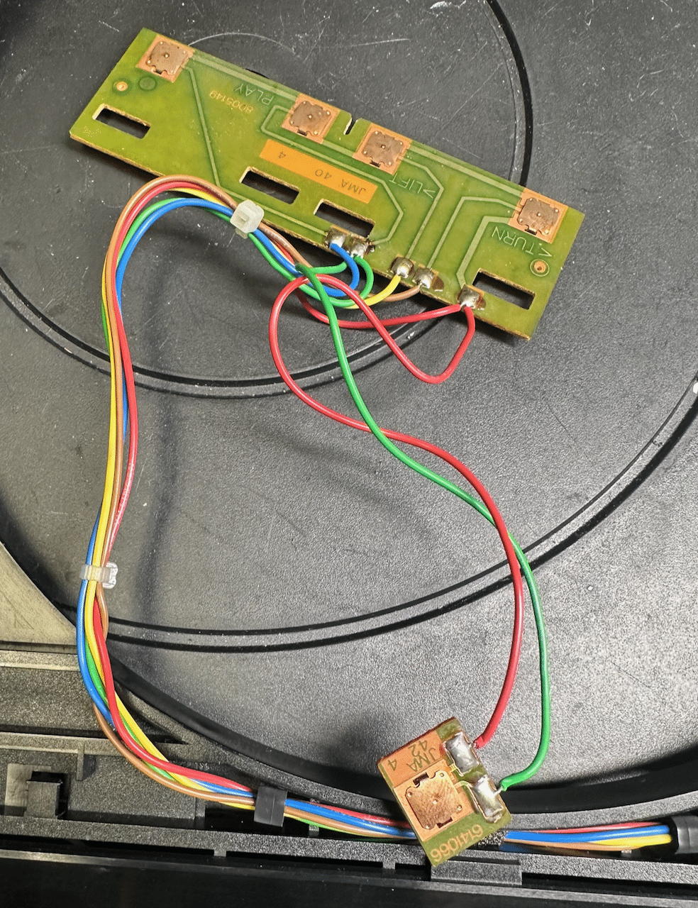
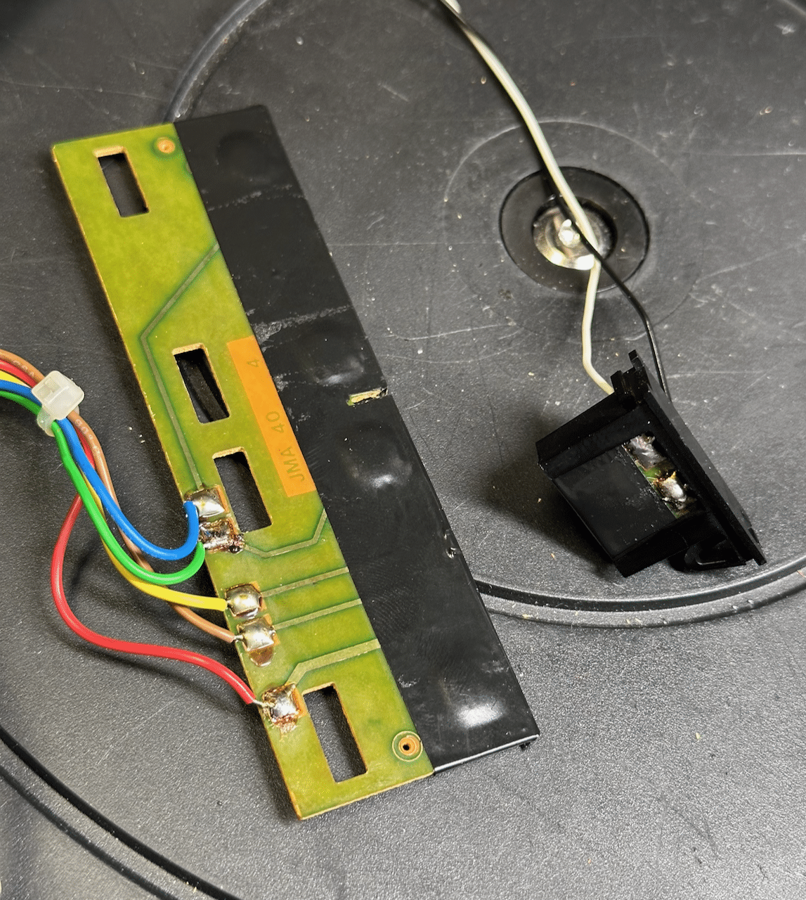
The “Play” button is fixed in place with a black bracket, which holds the button in the appropriate place on the front panel.
It’s wired directly to the “Play” button on the top surface, so it only can perform the same function as the “Play” button under the cover. The large PCB3 is removed by carefully moving the 4 black tabs that hold it firmly in place, and wiggling the PCB up and back out of its mount.
I was surprised to see that these buttons were exposed – typically, they are covered with black tape to help hold them in place (and probably also to keep moisture and debris out from them – they are a slightly cheap design, and can easily be made inoperable with a bit of contaminant). I fixed the vulnerability by adding a bit of electricians tape myself. Next, I severed the connections of the small PCB, and added two additional wires to it, per the new design specification.
Last, I ran these new wires back through the cover, using the same clamps used for the existing wires. A bit of trimming later, and everything was hooked up per the late-model specifications. A fairly straightforward modification.
I’ve elected to not add an RIAA to this unit, as I need something I can use to test with earlier variants of Beomasters with built-in RIAA. So this unit is upgraded as much as it can be, and ready for work.TKBRONZE MemberI took delivery of another late-model PCB1 control board (with the discreet Play/Off hookup), so I decided to replace PCB1 on my 5005, and do a bit more analysis of this late-model feature.
This additional feature basically provides continuity over the component range, as compared to the earlier Beograms where the button was a mere extension of the “Play/Repeat” button located inside of the cover. The original Datalink status sent by the original Beogram 5005 thru 5500 was “Play/Repeat” is a single Datalink command “Beogram.Status.Playing” when first pressed. Subsequent presses of the “Play” button put the Beogram in ‘Repeat’ mode, and were handled without sending any additional information back to the Beomaster. In fact, this was a missed opportunity by B&O to send a ‘Status.Counter’ to update to the MCP on any ‘Status’ request, showing the number of queued repeats – for example, the Beogram could easily have been coded to send “Beogram.Status.Counter ‘C 03’ “, reporting back to the MCP screen the number of record plays remaining – a trivial code addition which could have provided some visual feedback to the listener as to the number of repeats remaining.
Conversely on the late PCB1 board, the pressing of the front button while the Beogram is playing sends two Datalink commands: “Beogram.Status.Standby”, followed a few seconds later by “Beogram.Status.Stopped” when the platter stops spinning. Sending the Standby command will cause the Beomaster to act accordingly.
If I ever find the time to create a replacement microcontroller for the Beogram, I’d like to add a feature-set which provides more status reporting to the listener. Repeats, song count (based on 3 seconds of silence, for example), 33/45 selection via the MCP, and things of this nature would make excellent upgrades to the base system.
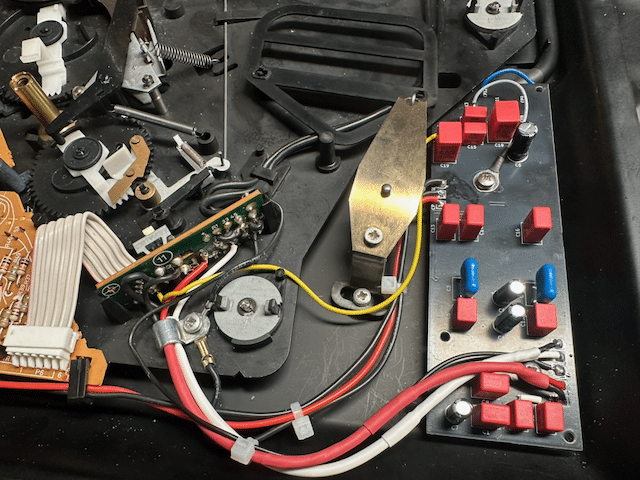
TKBRONZE MemberOn to the final steps – finish routing the wiring, and connecting the RIAA. The original wires ended up being just a bit short to wire around the underside of the board as I would have liked, but at this point I didn’t care – I wanted to see if my upgrade had worked!
With the wiring complete, I re-calibrated the board based on the service manual (recall, I had swapped out the original 5500 board with a later board that had a discrete “Play/Off” feature, like the Beogram 7000).Moment of truth! Triple check to make sure everything was as-planned, and hook it up to my Beomaster 7000. Everything worked as expected – Lovely! Special thanks to @adyan for making a few RIAA boards for this project. I have no doubt the TX-2 will work as well, but I’ll go through the steps to document the process.
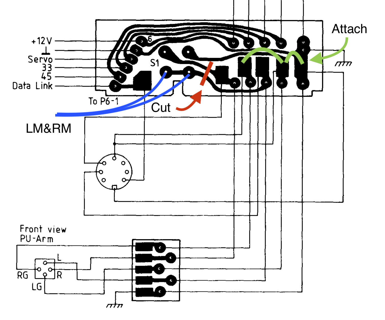
TKBRONZE MemberOn reading, re-reading, and re-re-reading the latest version of the service manual RIAA schematic, I came to the conclusion that the “Old Version” PCB 11 would need a modification in order to electrically emulate the “New Version” mute circuit. The original PCB11 is wired such that LG and RG from the stylus are not connected to chassis ground or shield ground until the wiring reaches the Beomaster. Further, the mute circuit is implemented by grounding the L and R to LG.
New boards designed for dual use as RIAA or non-RIAA implement a sightly different protocol, which necessitates the cutting of a wire bridge between some of the solder pads to achieve the desired circuit. Also, the LM and RM wires work a bit in “reverse”, where the mute circuit acts to ground the amplified signal on mute activation, before it reaches the output cable. The only way I could see to mimic this implementation was to grind a cut on the PCB itself, isolating L and R from the original mute circuit. [EDIT – I’ve made a small change to the schematic, and included both versions for comparison]
Original Version combines L+ R during ‘unmute’ – potentially undesirable:
Final Version – isolates L&R outputs during ‘unmute’:
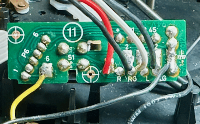
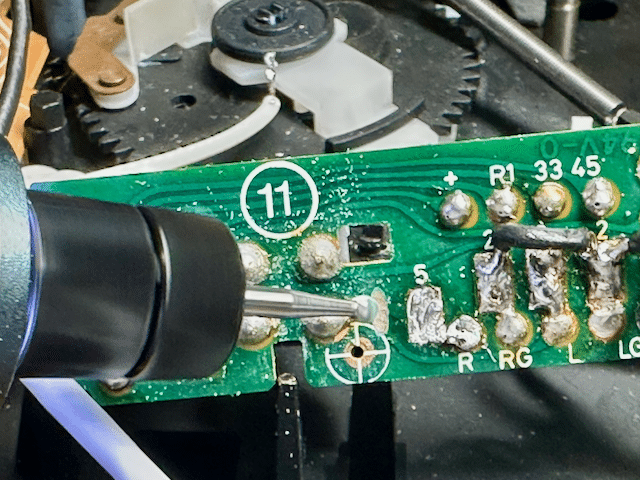
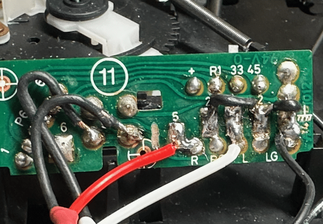
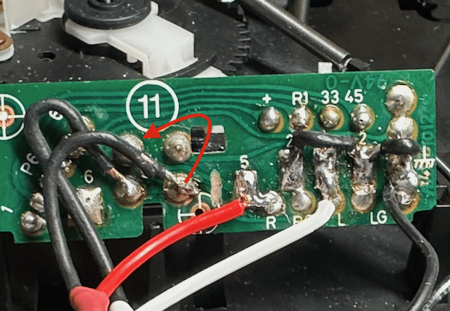
With that mental hurdle cleared, all that remained was to wire PCB11 with a jumper between LG, RG, and chassis ground, which meant that the mute circuit was now also connected to chassis ground. I considered that LM and RM are really the same signal and could actually just be activated together using a single wire [EDIT – I’m not actually sure this is 100% true in all scenarios, although it did appear to function correctly], but I went ahead and wired a separate LM and RM to the mute switch, per the schematic. [EDIT – even though the Original Version worked as wired, I realized later that I’d connected L+R in a way that might lead to some odd behavior when unmuted, so I moved one of the channels to a new position, where they would be isolated during ‘unmute’. The original wiring solution didn’t seen to affect the performance of the circuit, but the final version is representative of the original schematic] With L & R inputs reattached in their original spot, I was set to finish wiring up the RIAA.Original Version:
Final version:
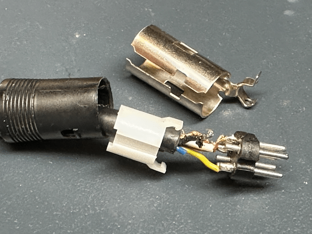
Admittedly sloppy, but it all toned out properly, so I left it as-is, and re-installed PCB11.TKBRONZE MemberI decided I’d upgrade the 5500 first, on the thought that the wiring would be a bit easier. This proved to not be the case – B&O supplied the original output cable with an extra unattached blue wire, which was not connected to pin 7. I made the decision to disassemble the Din connector to attach it. This is strictly not necessary for my planned use, but I wanted to observe the convention that “Beograms with RIAA run Datalink on Pin 7”.
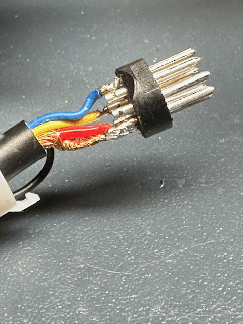
Upon disassembly, I found that not only was the blue wire not attached, it was truncated to the point where I’d have to un-solder all the pins and re-cut them to the new length. This is fiddly work which I’m personally not terribly fond of. I just happen to appreciate the coolness of a removable pin 6 and 7, and want to preserve that feature. I wired up both pin 6 and 7 with the blue and yellow wire. Without thinking about it first, I moved the yellow wire to pin 7, and soldered the blue wire to pin 6. Inside the turntable I’ll have the blue wire available on pin 6 for a future new project I’m dreaming about.
After a bit of squinting, cursing, and double checking my work for shorts, I was ready to reassemble the connector. Then came the “one-way” step of snipping the cable at a point I thought would provide enough wire on either side of the RIAA card to connect everything together using the original wires.
TKBRONZE MemberI’ve used both Vishay 47uF 25v (MAL202136479E3) and 33uF 16v (MAL203035339E3), and both single-cap changes alone have restored the individual players to full operation. I can’t speak to whether these are the best brand/model choices, or whether a 47uF provides better tracking, but some have reported better results using a 47uF, saying that they are better equipped to read more modern discs. This has all been in the last year, so I have no longevity data.
I also don’t have a list of “while you’re at it” parts swaps, which would be a nice thing to have, if others have a list.
TKBRONZE MemberNext step is adding a power plug for the RIAA amps I purchased from adyan. His design mimics the original RIAA boards used in the 6500-7000 models, and therefore also needs a 22V and 12V supply, which it gets from the transformer on a plug from PCB2. None of my US-Spec TX2 transformers – early or late models – have this 2-pin plug, so I had to tap into the PCB at the correct spots. Here again I contemplated drilling PCB2 to add a surface-mount plug. And once again, for simplicity I opted to add a pre-wired 2-pin connector instead. I attached the red wire lead to the existing 12V wire hookup (post IC), and the black wire lead to the 25V output from the rectifier. This way, Red would consistently be the 12V supply. The plugs are male/female, so there’s no way anyone could accidentally feed a 25V input to PCB1 ground by mistakingly hooking up the incorrect plug.
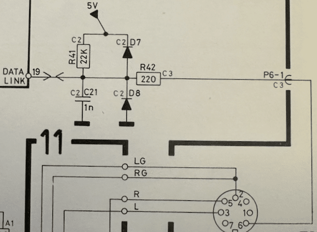
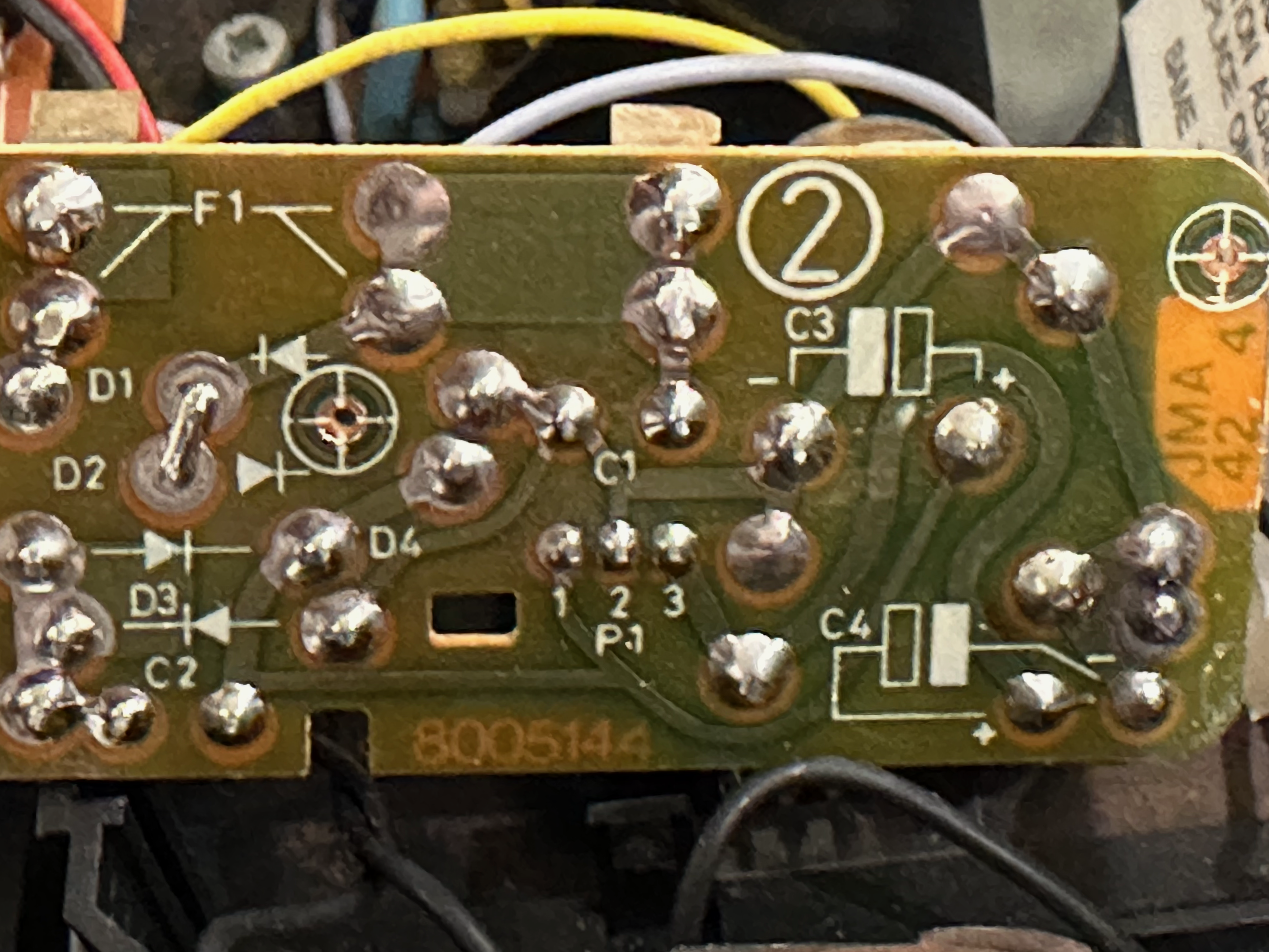
With these straightforward updates completed, I’m ready to tackle installing the RIAA board. I’ve opted to upgrade my 5500 and TX-2 simultaneously, in order to teach myself a bit about both upgrade paths.TKBRONZE MemberHere’s a “Old vs. New” 59XX schematic connecting the CPU to the Datalink bus. The new schematic includes a 547 transistor and 10K resistor hardwired to 5V, so it will be active as soon as the Beogram is plugged into power.
OLD SCHEMATIC
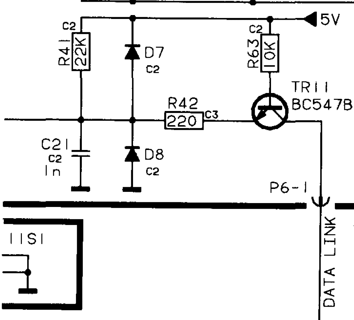
NEW SCHEMATIC
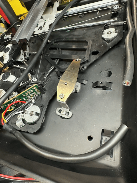
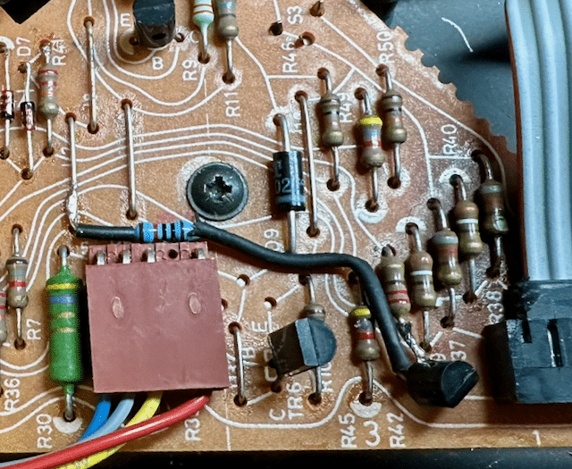
It turned out to be a fairly straightforward process adding a transistor to PCB1. I took a 547 equivalent transistor, and soldered a 10K resistor to the B pin, and added a bit of heat shrink to prevent a short. Next, I repositioned R42 by removing the Datalink bus leg from the board, and soldering it to the C pin of TR11. Last, I placed the TR11 E pin into the now-empty hole which previously connected R42 to the Datalink bus, completing the circuit. I contemplated drilling holes in the board and routing the wire underneath the board, but in the end my eventual solution was much simpler to execute, and I think it turned out looking OK – the parts are basically in the same spot they would appear in a later board, so it will be simple enough to understand what the retrofit’s purpose is. This is a picture from a 5005 board I had retrofitted earlier:
TKBRONZE MemberWith the Beogram power supply, the story is much the same as the main PCB – the supplies all have the same basic capability across models, but depending on the model and region, the way they were wired varies slightly. With the deployment of an On-board RIAA of the 6500, it became necessary to power the IRAA via two power feeds from the PS. This necessitated the inclusion of a small 2-wire pin to the PCB, from where the RIAA could be powered
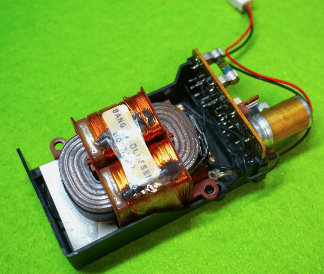
Of the US-based TX-2 that I’ve seen, it appears that both early and late examples utilized the power supply setup as seen below, irrespective of which generation main PCB was installed. This supply was wired for 120V, with a large fuse taking up much of the PCB #2 real estate, and no support for an RIAA hookup:
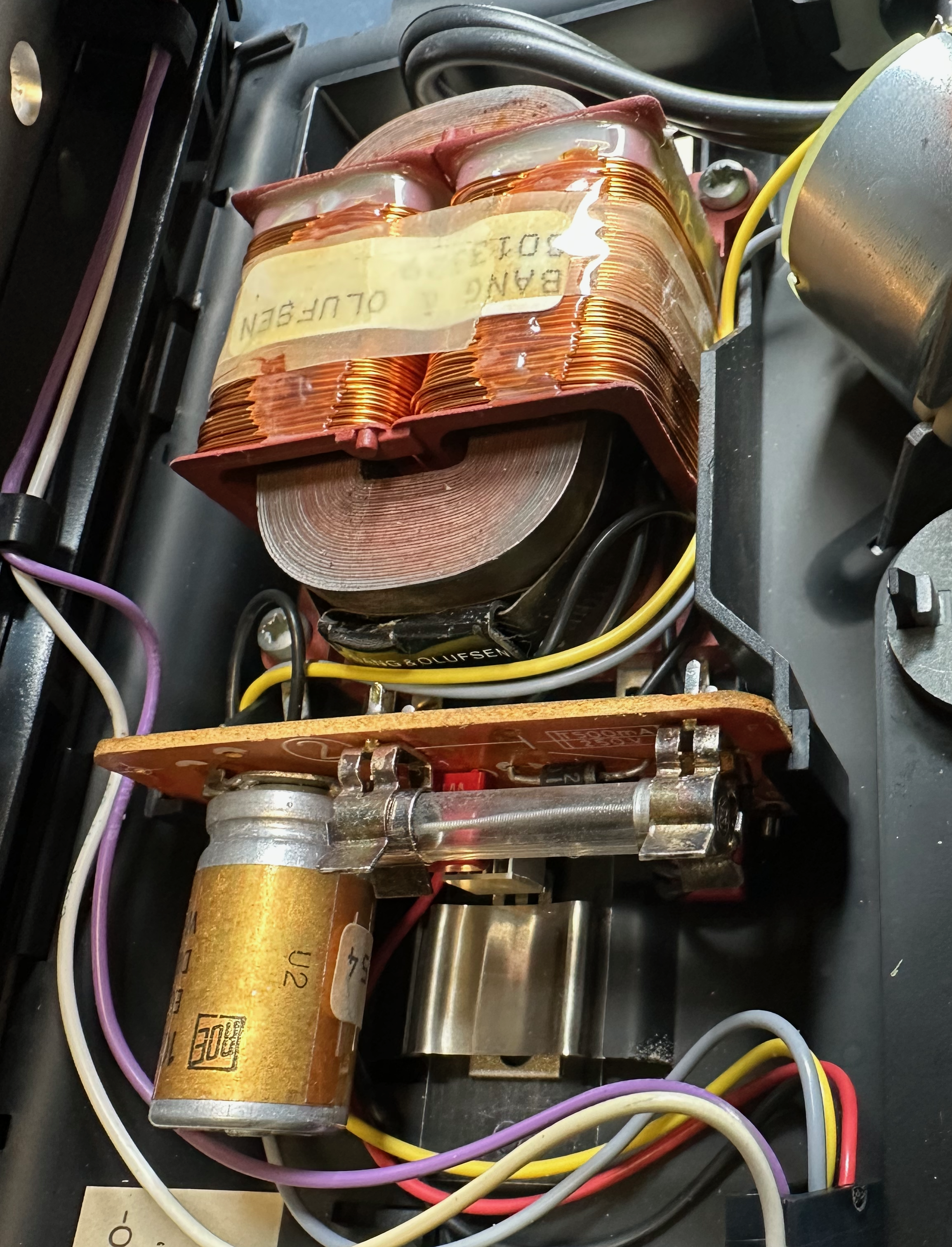
Later Euro TX-2 examples appear to have the 2-pin RIAA hookup, as shown here (photo 1 supplied by adyan, who has extensive knowledge on RIAA for these systems, and has supplied me with a pair of boards for this upgrade)
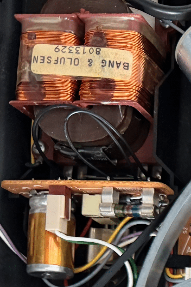
Here is a picture of a BG 6500 PS, which resembles the example that adyan has in his late TX-2, and also has the 2-pin power hookup.:
These 2-pin RIAA hookups draw from power points which are readily accessible from any of the TX-2/5500 ps, but it does require a bit of retrofit work to tap into them. My plan is to solder a plug onto the board that will allow access to the same power that the boards with built-in RIAA hookups have. On the board below, soldering a hookup to the bus leading to pins labelled 1 and 3 (center of board) of the IC I/O will give the needed result of having a 22V and 12V supply, respectively.
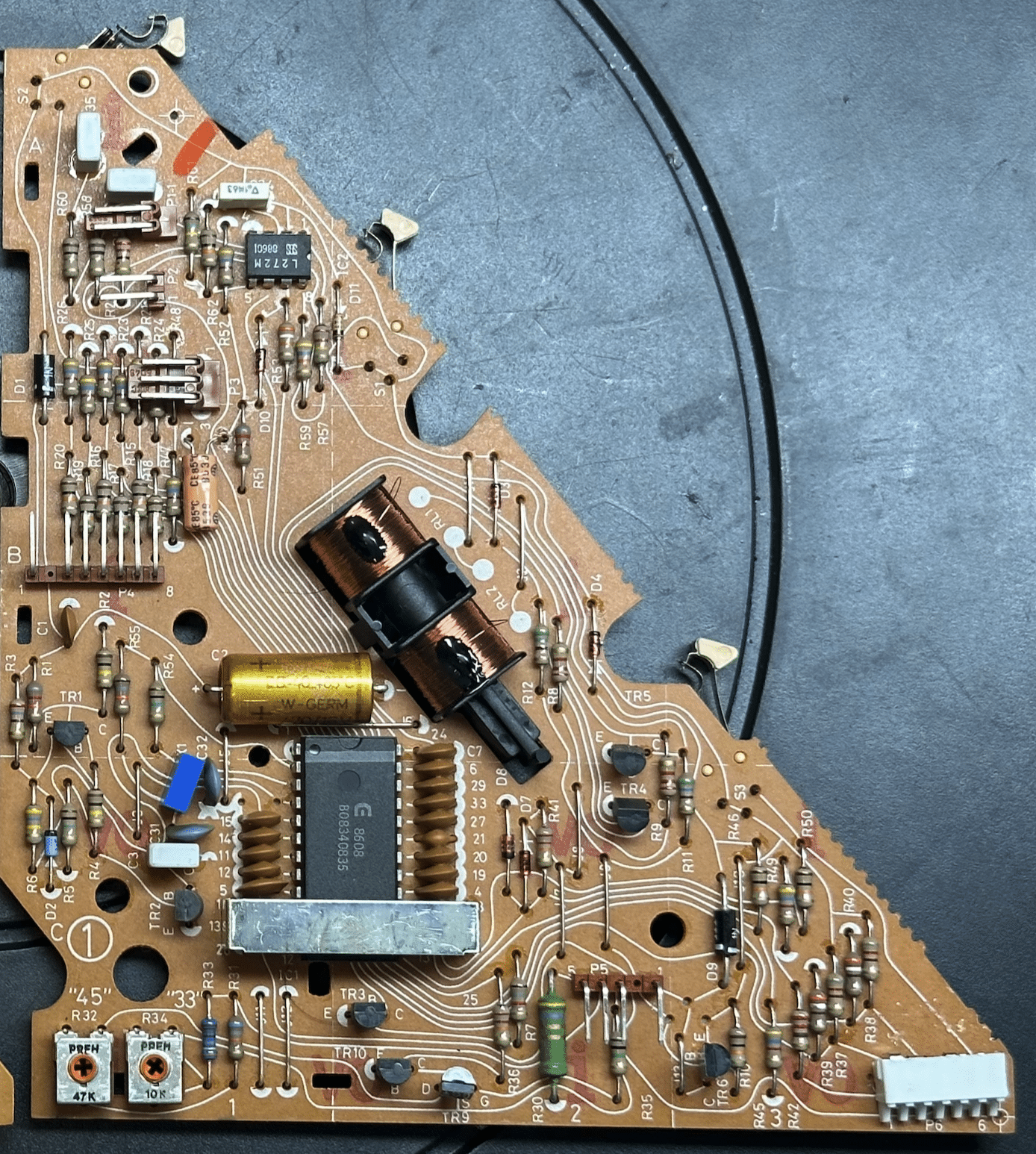
TKBRONZE MemberI’ve had the opportunity to tinker around a bit with a few TX-2 / 5500 PCBs – I used to think that they are nearly identical across the various iterations of Beograms from the 3000 to the 9500, but it turns out there were additional subtle improvements, as one might expect with the introductions of several models. I’ve outlined some of the changes that I can spot – perhaps there are more changes that others know of.
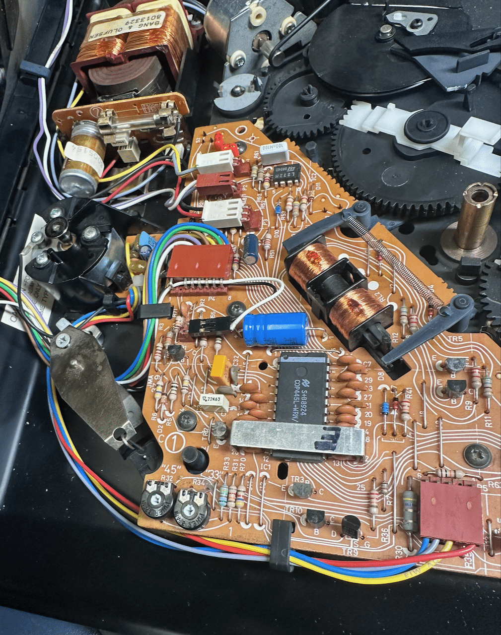
Here’s an example of an early 5005/TX-2 board:
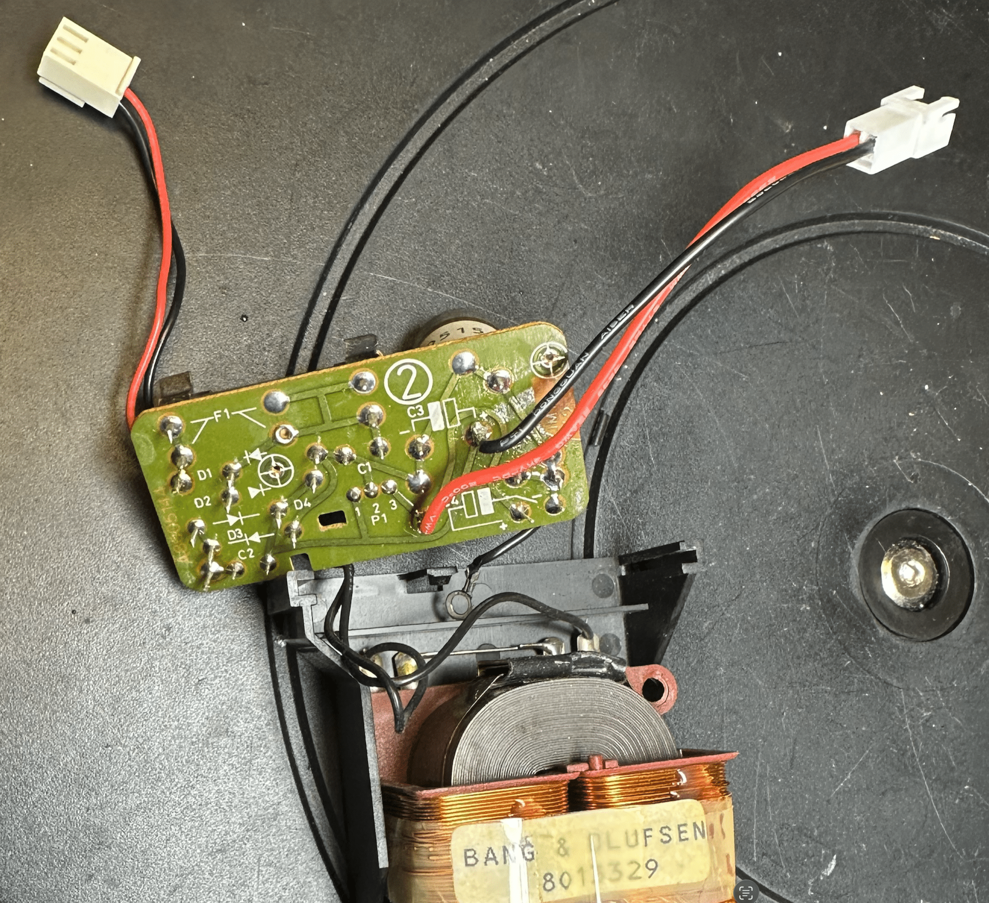
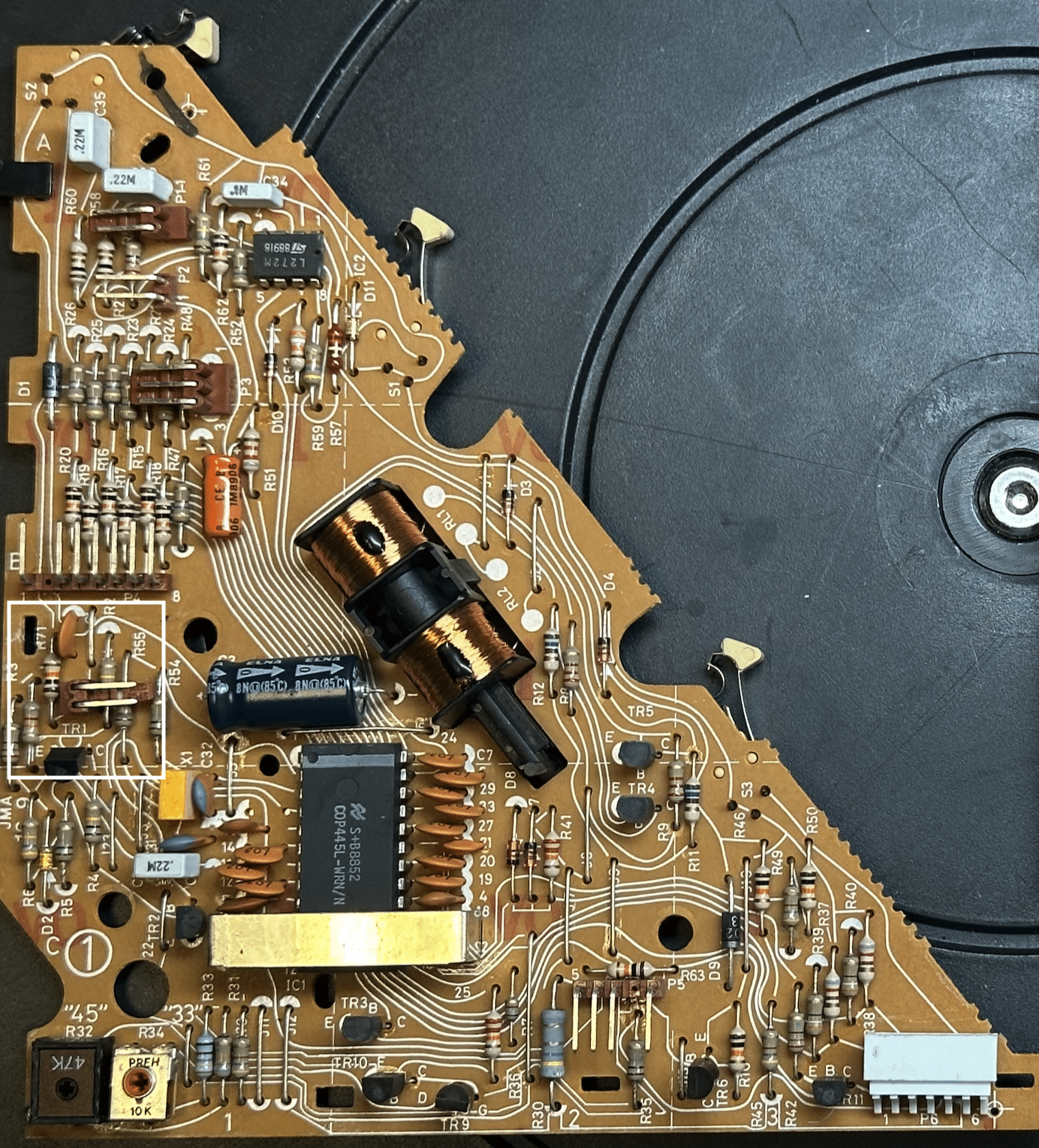
A 5500 board looks like this below. It adds a Transistor TR11, whose stated function is to keep the Datalink network working even when power is cut to the turntable. Early 5005 boards did not have this transistor, and B&O must have discovered that Datalink stops working if the 5005’s power is cut, driving the CPU I/O low:
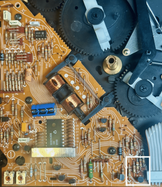
The last board I have for comparison is a late board from a TX-2, which has all the modifications used in the 7000 that I am aware of. In addition to the TR11 (which is only used for the 6500/7000), it also has a new microprocessor with a dedicated pin running to the front-facing “play” button. I’m taking this to mean that the outside button is now meant to function as an “play/off” switch, as opposed to a “play/repeat” switch:
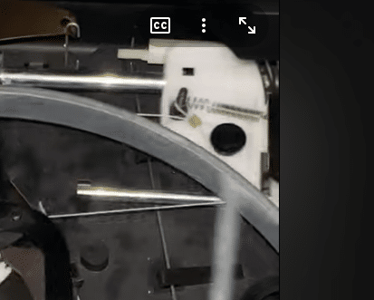
With respect to the differences, it’s a fairly straightforward procedure to add the TR11 transistor, which I’ll do for this upcoming specification upgrade. This also serves to decouple the CPU from having direct exposure to the Datalink pin, hopefully giving the CPU a bit of protection from problematic external hookups. There’s not a whole lot I can do about implementing the “Play/standby” function vs the “Play/repeat” function, as I want to use the late board I have (the one with all the upgrades) in a 5500 upgrade instead of a TX-2. More on that upgrade in a little while. For now, I’m going to add the TR11 upgrade, and call it good enough. I’ve found a few other improvements (mostly to support the addition of RIAA) which I’ll detail in a subsequent post.TKBRONZE MemberSorry, I have nothing but problems adding inline images to this site from work (seems to work better at home) , so I’ve included a photo as an attachment instead of an inline photo. The retention tab was broken on your machine, and replaced with a metal pin of some sort. There’s no reason I can think of that retrofitting a new pin wouldn’t work, provided it’s in roughly the same place. But it appears that they’ve over tensioned and ruined the spring, which raises more questions about what else happened with the unit under their care.Have you tried re-seating the cartridge to see if it sounds better?Attachments:
You must be logged in to view attached files.TKBRONZE Member
The carriage string and the tension spring are installed onto the carriage in a way I’ve not seen before. It looks like they’ve stretched the spring to the point where its less spring-like I’d venture to say they snapped off the original string and tension spring mount on the carriage, and fashioned a new mount out of a screw. That in and of itself is not a problem if done properly. The installation of the string itself might need a bit of checking, but it does appear to roughly work as-is. I have not checked too closely, but at first glance, the gears all appear to be working properly. I do wonder if the jitter you see on startup is caused by a belt issue, perhaps by one that is not fitting quite right. Did they mention if they replaced it?
Also to add, in reviewing the movie you posted 2 days ago, I’d ask you to affirm that your cartridge is fully seated in the arm. It might just be the angle, but there appears to be a gap between the rear of the cartridge and the mount.
If the cartridge is affirmed to be fully seated (no gap), then the arm skating across the record is another matter, and is potentially an adjustment needed to the arm balance. You mentioned they remade something in the stylus head – by that do you mean the location where the arm attaches to the carriage, or do they mean the same fix of the broken string mount on the carriage? If there is damage to the arm that they attempted to repair, then this is where finding a used-but-working TX-2 can help you fix both issues – AFAIK the entire carriage assembly is a direct swap, and it will most likely come with an unbroken mount on the carriage as well.
TKBRONZE MemberThat is a shame! Try this: remove the MMC cartridge and set it carefully aside, then remove the black cover to the platter drive wheel- it should just lift off. Leave the belt in place, so it turns the bottom platter pully. Place your finger to put a bit of pressure on the central disc to hold it down, and hit “play”. After the system starts spinning, you can remove your finger off the disc. All the while, point the camera at the exposed gearset. Try moving the arm left and right. Then hit stop, and post that video next.
There is a bit of good news with respect to spare parts. Most of the 7000 internals are shared with the TX-2, including all of the mechanical parts (AFAIK), so with the current cost of a BG7000 in the stratosphere, you should easily be able to find a complete donor parts machine for 50 pounds or less, which a skilled technician can use to carefully transfer over the needed parts into the 7000 case with relative ease.
TKBRONZE MemberA tired belt may not be your exact cause, but I’ve solved the wow problem before by simply using a slightly tighter/new belt. Consider also removing the platter and check for anything which may be rubbing against the pulley – wires, gears, etc. If you remove the belt and spin the platter clockwise it should spin freely without any rubbing noise for a considerable length of time.
If none of that works, I’d imagine that you’ll have to start looking at the PCB voltages. There are probably others more seasoned than myself who can advise.
TKBRONZE MemberUsing your example above, given my understanding of MCL2 and the MCL2AV, I think what is happening might look more like described below. I’m going to ignore for the moment the IR piece, which I think can be viewed as another way to send and receive MCL2:
Beo4: MCL2 (One way) Sends wireless MCL2
BM5500: MCL2 (One and two-way) wired MCL2 through Speakerlink. Also has its own wireless MCL2 gateway, which you can turn “on” or “off”, depending on your setup.
MLC2AV: MCL2 wired Gateway (One and two-way); sniffs out a few select MCL2 commands to act on, such as Mute and Play. Can send and receive MCL2 to the BM, or towards the Sensor.
Sensor: MCL2 wired-to-wireless Gateway (one and two-way); converts wired MCL2 into wireless MCL2, and vice-versa. Collects IR data from whatever remote is sending in the room, and passes it to the MCL2AV. Can also receive wired MCL2, convert it to IR protocol, and broadcast to the room. Has a few physical buttons used to inject pre-programmed MCL2 commands onto the wired network towards the MCL2AV gateway, such as “Mute” and “Standby”.
This is just the MCL2 piece. Then there’s an ML piece, of which there’s a Gateway which can convert MCL2 into ML, and vice-versa. From what I recall, these components were in constant development, so it’s important to get one that has the absolute latest firmware release, which can correctly translate the most messages correctly.
TKBRONZE MemberI’ve done a fair amount of documenting on all things MCL/MCL2, and almost nothing on ML. Here’s what I can add to the conversation. This is all probably not exactly 100% accurate, but IMHO it’s probably reasonably accurate for the purpose of this discussion. Here’s a primer:
- Beo4, Beolink 1000, Master Control Panels, Beolink 7000, MCL2AV + sensors, Pentas, several other Beolabs, and BeoMaster 5500-9300 – any peripheral with a Powerlink plug, as well as some of the all-in-one tabletop boxes, all can communicate with one-another using Datalink ’86, or MCL2 for short.
- Some newer components have both a Powerlink and a MasterLink connection, in which case they broadcast/receive both ML and MCL2.
- Newer-still components dropped the Powerlink connection, in favor of just ML. To attach an MCL2 system to it, you’d need buy some B&O converter to add inter-connectivity.
- The Beo4 and Beolink 1000 use the simplest MCL2 format, designed for 1-way communication, which I call “AC” format (“Address-Command”). A Slew of B&O systems can understand and act on these commands. Anything which can be directly controlled using a Beo4 can effectively decipher one-way MCL2.
- The MCP and the BeoMaster 5500-7000, and the 9500 use a myriad of 2-way communications formats of various types and data lengths. Only systems designed to handle 2-way communication protocols can act on these messages. These formats are all part of the MCL2 protocol, and are defined as MCL2. Only some B&O systems are designed to decipher these more advanced 2-way protocols.
- The MCL2AV appears to be primarily an MCL2 Gateway between the BM and a sensor. It will pass through most of the data it sees on the bus in a 2-way fashion, regardless of whether it’s a simple or advanced MCL2 message. If it’s identified as being an MCL2 structure, it will send it onwards. When it sees a few select commands come from the sensor that it understands, like a source selection, Play/Mute/Standby, it turns it’s own speaker pair on or off, and plays whatever is on L&R channel, or it’s own inputs, depending on how it’s set up. One might say it’s kinda/sorta like a limited-function BeoMaster.
- The BL7000 uses the most sophisticated variant of MCL2, which AFAIK only it and a BM7000 can encode/decode into meaningful messages (although it is backwards compatible for message transport purposes, and can still be seamlessly passed through any of the attached linked systems, including an MCL2AV, as far as I’ve been able to test).
- For the sake of completeness, there is also an earlier protocol called MCL’82 that predates Datalink ’86 (I personally refer to it as just “MCL”, which is not really accurate), which AFAIK is only used on the BM5000 and its BM5000 Link peripherals, with some limited cross-compatibility with the BC7000.
Based on my research, MCL2 is a very robust and flexible/extendable system, with one major drawback – It ran at 320 baud. This meant it can take up to a second or two to send a full complement of system status messages. IMHO this was a bonafide revelation in the mid 80’s but totally antiquated by the mid 90’s. For example, implementing RDS on the BL7000 involved sending three messages at .5 seconds each, and takes almost 2 seconds to send just 10 characters of data, with header/control information in tow. Imagine if you had to send a CD’s worth song names over MCL2 – it could take a minute or more, and clog up all the transmission/control lines in the mean time.
I have not yet dug into ML and its underpinnings, but at some point I’ll look into it. I can only assume they solved all of these speed issues.
-
AuthorPosts