Forum Replies Created
-
AuthorPosts
-
quattttro
BRONZE MemberWould be a cool project. What kind of modernization were you thinking?
quattttro
BRONZE Memberquattttro: Have you made any more progress? I revisited my BM6000 that doesn’t power-up properly. I was able get it to work with a known working good CPU from another BM6000. Now I’m very confident that the original CPU is bad. With the bad CPU, I observe two different (pseudo-random) behaviours when I plug-in the receiver. The first is a “:.” display, the second is a “.” display with the main amp rail relay kicking in. Glitch
No progress. Sits on my workbench, haunting me. I’m pretty sure mine has the same problem though, a faulty CPU. It is consistently unresponsive “.:”, & the main amp relay never kicks on unless I mess with the startup timing. Shame to turn it into a parts unit, but not much choice.
quattttro
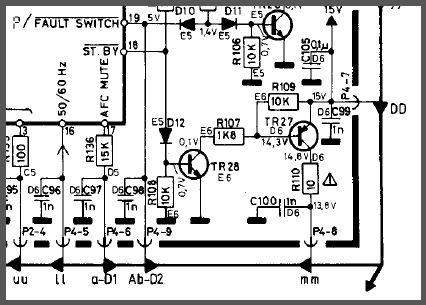
BRONZE MemberSorry but if you have 15V at emitter TR27 and 14.3V at Base then TR27 as a PNP type should turn on. (0,7V on its BE-diode) I would check TR27… hx
TR27 tests fine on the transistor tester, nonetheless, i swapped it out for another one. Same thing, nothing on the collector. In any case, this is probably secondary, as the relay should not be switched on in standby mode.
quattttro
BRONZE MemberThanks a lot for your help, Glitch. Hopefully I’m missing something obvious, will continue to work on it.
One final question, how does the “St.by” circuit work on board #2? Specifically around TR27. I know it gets 15V from board #6. I’ve got 15V at the DD (TR27 emitter) and 14.3V at the base, but then nothing on the collector (if I did, the relay would switch on). I’m guessing this tells me the CPU is not providing the necessary signal and TR28 is not pulling to ground? Thanks again!

quattttro
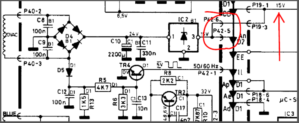
BRONZE MemberSame 14.7V on P42-5 with P42 wires pulled. Interestingly, I get “P” in the display when P42 is pulled. It never displayed anything before save for the colon, dot, and radio LEDs.
Definitely have both 5V supplies. I get a perfect 5V at the CPU pin 40 and the other ICs on board 2 are all getting 4.9v from the 2TR1 supply.
I am getting some sort of signal from the CPU’s 50/60Hz pin (16). The waveform looks exactly like your did on page one of this thread. Even has the same blip on the right side of the square.
quattttro
BRONZE MemberI’m probably getting desperate, but would 14.7 volts here cause a problem? I know this 15v goes to the standby circuit amongst many other things. And I’m not getting 5V on Pin18 of the CPU (st.by), though i’m probably running into that chicken/egg problem again 🙂
I’m getting 14.7volts at pin 3 of IC2 (board 16).
quattttro
BRONZE MemberAdjusting R25 solved the motor always-on issue. The full calibration procedure requires the receiver to be on so the volume can be adjusted to various levels.
quattttro
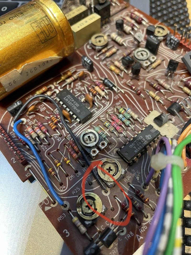
BRONZE MemberPerhaps unrelated, but I noticed resistor R27 has been snipped out of my motor control board. Looks to be related to the volume control. Is this a factory thing, or should I install a 470 ohm resistor there? I noticed the resistor present in Sonovor’s thread, here.
Missing R27:
quattttro
BRONZE MemberOk, thanks. I guess i was following it backwards.
My machine does not power up. When plugged in I only get the standby light and clock colon. The radio LEDs glow and volume motor spins endlessly too (despite pot position). Nothing happens beyond that. Buttons do nothing.
quattttro
BRONZE MemberWhat about Pin16 on the cpu (the 50/60Hz signal)? This signal comes from TR4 on the power supply board # 16. I’m not getting a square wave from the collector of TR4, but I might not be measuring correctly. Is this signal required for CPU startup?
quattttro
BRONZE MemberIt does now, yes.
quattttro
BRONZE MemberExactly. Mine has the same mark/cut. Part of the modification, I guess.
In other news, after replacing R89 again, I was able to get around 2.3V across R95. Did not solve my issue, however, as the 6000 still won’t fire up beyond colon and standby dot on the display.
quattttro
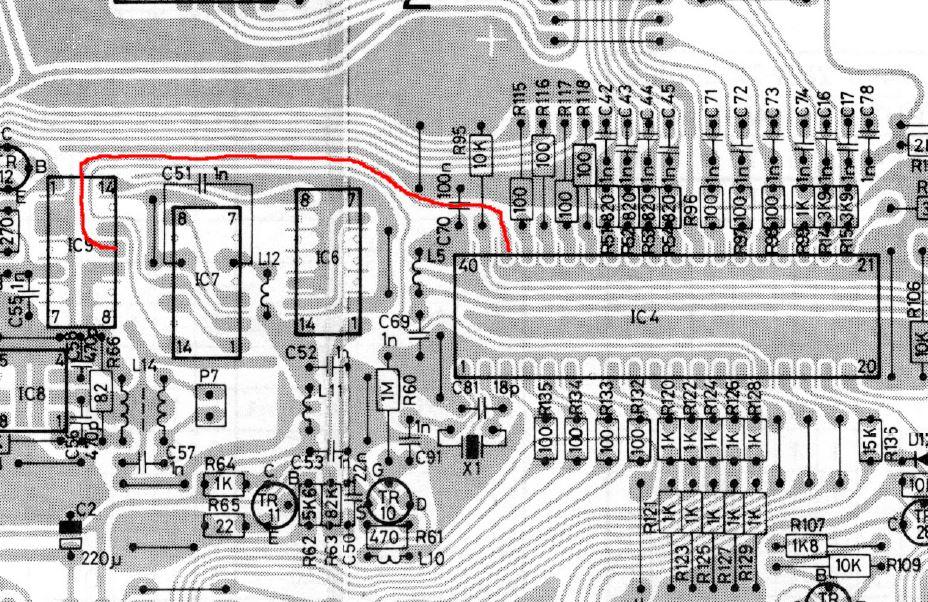
BRONZE MemberPerhaps this is normal, and part of the modifications for the extra add-on IC board, but I noticed this trace in red between IC4 (38) and IC9 (pin 11) was severed. Should it be?
quattttro
BRONZE MemberJust to confirm, I remove P5 connector completely, inject 4.6V to pin 3/4 of P5, then monitor the voltage across R95 with a multi-meter (service manual says to use an oscilloscope).
One thing i’m unclear about is the ground situation. If I understand correctly, removing P5 also removes the chassis ground wires from microprocessor board 2. I would need to connect power supply ground to a ground point on board #2, and not the chassis ground point up by the amplifier board.
Thanks again, Glitch.
quattttro
BRONZE MemberOk, using a series resistor and a power supply, i think 2D6 tested OK. The transistors TR5 and TR6 tested OK on the tester too.
I re-did the Reset adjustment procedure after testing. After moving the ground connections from the power supply around I was able to see 3V on R95, but adjusting R89 did not change this voltage at all. I’m at a loss 🙁
Thanks for the help!
quattttro
BRONZE MemberI pulled D6. In diode test mode on my MM, i get 0.6V one way, then 1.28V in reverse. It should be OL or infinite in reverse, am i correct here?
quattttro
BRONZE MemberYes. 6.5V on P2-2 and 5V on P2-3.
quattttro
BRONZE Memberyes, 5v CPU (pin 39, iirc) and the other voltages are all exactly as noted in the service manual. I did try to adjust the reset circuit, but I get 0V across R92. I’m not really sure why that is.
quattttro
BRONZE MemberDid you ever figure out if the CPU was dead on your 6000? Mine exhibits the exact same symptoms, unfortunately.
quattttro
BRONZE Membery’know the springs you get in picture frames to push the backing against the glass? Those work well as an alternative.
-
AuthorPosts


