


Home › Forums › Product Discussion & Questions › BeoMaster › Beomaster 6000 Power-On Issue
- This topic has 70 replies, 8 voices, and was last updated 1 year, 6 months ago by
 Jorgr Alvarez.
-
AuthorPosts
-
10 January 2023 at 14:31 #36705
 GlitchBRONZE Member
quattttro: Do you have 5v on the secondary 5v circuit? If not, check the edge connections on the Microprocessor board for cracked solder joints, especially 2P2. Then check 2C65 and 2C2 for shorts.
Glitch
10 January 2023 at 20:49 #36706quattttroBRONZE MemberYes. 6.5V on P2-2 and 5V on P2-3.
10 January 2023 at 21:33 #36707GlitchBRONZE MemberAt this point I would just pull TR5, TR6 and D6 and test them. There is not much else to the RESET circuit if the voltages are all OK.
Glitch
10 January 2023 at 21:56 #36708quattttroBRONZE MemberI pulled D6. In diode test mode on my MM, i get 0.6V one way, then 1.28V in reverse. It should be OL or infinite in reverse, am i correct here?
10 January 2023 at 23:22 #36709GlitchBRONZE MemberI would expect about 0.7v forward and 2.7v +-0.1v in reverse (since it is a zener diode).
You might get a misleading reverse voltage reading depending on your tester. Testing with a series resistor, voltmeter and a power supply can be used to verify the reading.
Glitch
11 January 2023 at 22:29 #36710quattttroBRONZE MemberOk, using a series resistor and a power supply, i think 2D6 tested OK. The transistors TR5 and TR6 tested OK on the tester too.
I re-did the Reset adjustment procedure after testing. After moving the ground connections from the power supply around I was able to see 3V on R95, but adjusting R89 did not change this voltage at all. I’m at a loss 🙁
Thanks for the help!
12 January 2023 at 15:43 #36711GlitchBRONZE MemberYour results do seem to be unusual.
IIRC, the voltages should jump around quite a bit with small movements of R89. Are you sure that R89 is OK? At the very least, the original trim pot should be cleaned to ensure smooth, reliable contact. Better yet, a new trim pot may save you some headaches. The adjustment is sensitive enough that installing a 10-turn pot can be helpful. Be sure to exactly follow the procedure in the service manual. This is an adjustment where “close enough is good enough” usually doesn’t work very well ;-).
The only other thing that might give you more clues is to try the RESET adjustment with the CPU removed. I would do this as a last resort since the mechanical stress of removing the CPU might damage it.
Glitch
13 January 2023 at 03:02 #36712quattttroBRONZE MemberJust to confirm, I remove P5 connector completely, inject 4.6V to pin 3/4 of P5, then monitor the voltage across R95 with a multi-meter (service manual says to use an oscilloscope).
One thing i’m unclear about is the ground situation. If I understand correctly, removing P5 also removes the chassis ground wires from microprocessor board 2. I would need to connect power supply ground to a ground point on board #2, and not the chassis ground point up by the amplifier board.
Thanks again, Glitch.
13 January 2023 at 04:04 #36713GlitchBRONZE MemberYes, remove P5 completely. I believe that you are correct that removing P5 breaks the ground path back to the BM6000 power supply, so you will need to connect the bench power supply’s ground to Board 2’s ground. I usually either clip on to either the CPU shield or one of the ground vias.
I suspect that they call for a using an oscilloscope due to the high impedance of the o-scope probe (as well as a fast response for any readings). I would expect that a high quality multimeter would also work, but I haven’t tried it myself.
Glitch
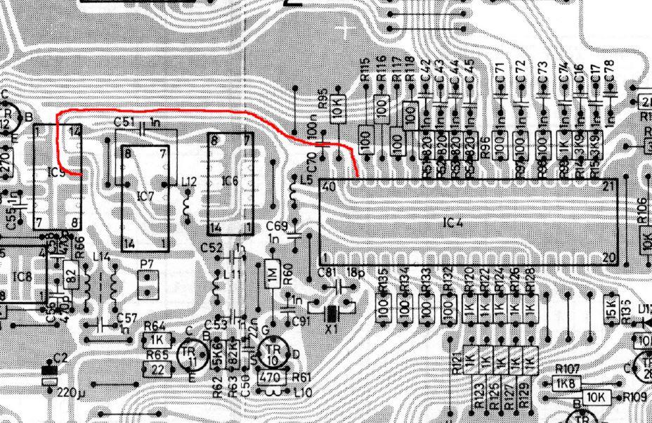
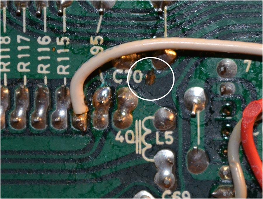
13 January 2023 at 18:40 #36714quattttroBRONZE MemberPerhaps this is normal, and part of the modifications for the extra add-on IC board, but I noticed this trace in red between IC4 (38) and IC9 (pin 11) was severed. Should it be?
 13 January 2023 at 19:31 #36715GlitchBRONZE Member
Like this?
 13 January 2023 at 19:57 #36716quattttroBRONZE Member
Exactly. Mine has the same mark/cut. Part of the modification, I guess.
In other news, after replacing R89 again, I was able to get around 2.3V across R95. Did not solve my issue, however, as the 6000 still won’t fire up beyond colon and standby dot on the display.
13 January 2023 at 20:20 #36717GlitchBRONZE MemberThe signal coming in on pin38 shouldn’t make any difference for the BM6000 starting up. It is related to the FM frequency display.
Does the voltage across R95 change when you adjust R89?
Glitch
13 January 2023 at 20:31 #36718quattttroBRONZE MemberIt does now, yes.
17 January 2023 at 17:49 #36719quattttroBRONZE MemberWhat about Pin16 on the cpu (the 50/60Hz signal)? This signal comes from TR4 on the power supply board # 16. I’m not getting a square wave from the collector of TR4, but I might not be measuring correctly. Is this signal required for CPU startup?
18 January 2023 at 00:09 #36720GlitchBRONZE MemberFrom the schematic, it looks like the CPU supplies the +5v for the 50/60 Hz signal (likely via a pull-up resistor on pin16). 16TR4 then pulls down pin16 in sync with the line voltage. Not seeing a signal could be that the CPU is not supplying the voltage to pin16 or that 16TR4 or 16D5 is bad.
What happens on pin16 when you power-up?
My best guess is that the 50/60Hz signal would NOT be needed to initialize. The only thing that I could think of it being used for is for the timer functions (which aren’t critical for operation). Then again, there could be a few lines of code that check for the signal changing and fault the processor if it isn’t as expected. I would expect the display to indicate a fault if this happened.
What is insidious about trying to debug this are the possible “chicken or the egg” situations that could be happening and not knowing if one is dealing with chickens or eggs ;-).
What does you display do when you power up?
Glitch
18 January 2023 at 02:29 #36721quattttroBRONZE MemberOk, thanks. I guess i was following it backwards.
My machine does not power up. When plugged in I only get the standby light and clock colon. The radio LEDs glow and volume motor spins endlessly too (despite pot position). Nothing happens beyond that. Buttons do nothing.
18 January 2023 at 05:14 #36722artigBRONZE MemberWhat about Pin16 on the cpu (the 50/60Hz signal)? This signal comes from TR4 on the power supply board # 16. I’m not getting a square wave from the collector of TR4, but I might not be measuring correctly. Is this signal required for CPU startup?
The signal on pin 16 is definitely required for a normal startup. If the signal is missing it goes into standby mode since this is normally an indication that there is a power failure. If there’s no mains power there’s really no point in going into anything but standby mode.
If you switch off the mains power (or disconnect pin 16 signal) while the unit is operating it will attempt a normal shutdown to standby mode, equivalent to pressing the Standby button.
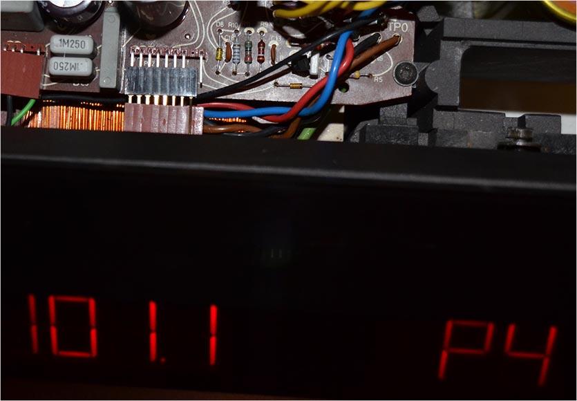
18 January 2023 at 05:52 #36723GlitchBRONZE MemberThe signal on pin 16 is definitely required for a normal startup.
I disagree, at least for my BM6000. Here is a picture of the the receiver running with pin P42-1 on board 16 disconnected (i.e. the 50/60 Hz signal).

The BM6000 does have some power drop protection, but it is implemented as part of the RESET circuit.
Glitch
18 January 2023 at 11:35 #36724AnonymousInactiveHi
-
AuthorPosts
- You must be logged in to reply to this topic.