Forum Replies Created
-
AuthorPosts
-
 hcraig244SILVER Member
Have a look at Rudi’s video below….could be the ES (End Stop) switch playing up.
hcraig244SILVER MemberAll of the above are the reasons I hold the vintage equipment in high regard, the BM6000 quad is a master class in over engineering, the lengths the B&O engineers went to just to make the indicator ribbons move up and down is staggering…and the logic gated control panel of the BG4000, given it’s primary role in life is to drop a stylus onto a rotating disc is also the work of someone with far too much time on his hands……
craig
hcraig244SILVER MemberI have a Beomaster 5000 which when it came to me had a replacement rectifier fitted now I come to think about it……
Craig
hcraig244SILVER MemberBy the way…..the BM5000 is a cracking tuner, there is some evidence that the BBC once held three or four to use for monitoring the strength and quality of the signals transmitted back in the day.
Craig
hcraig244SILVER MemberAre you sure the lamps you have purchased are specifically for the BM5000 tuner? wrong mA rating plays havoc with BM4400 tuners, I dont have a circuit diagram for the BM5000 tuner to hand but do have one somewhere…make sure the lamps are correct (check with Martin AKA Dillen from this site to confirm)
Craig
hcraig244SILVER MemberBeautiful cabinet work….and attention to detail cosmetically…..I would have liked to see/hear more about the rest of the restoration work both electrically and mechanically, I’m imagining it will have been extensive considering the condition of the cabinet when it came to you…please detail the process you followed for this for our continued entertainment ;¬)
Craig
hcraig244SILVER MemberI’m struggling to access the product manuals….is there an issue?
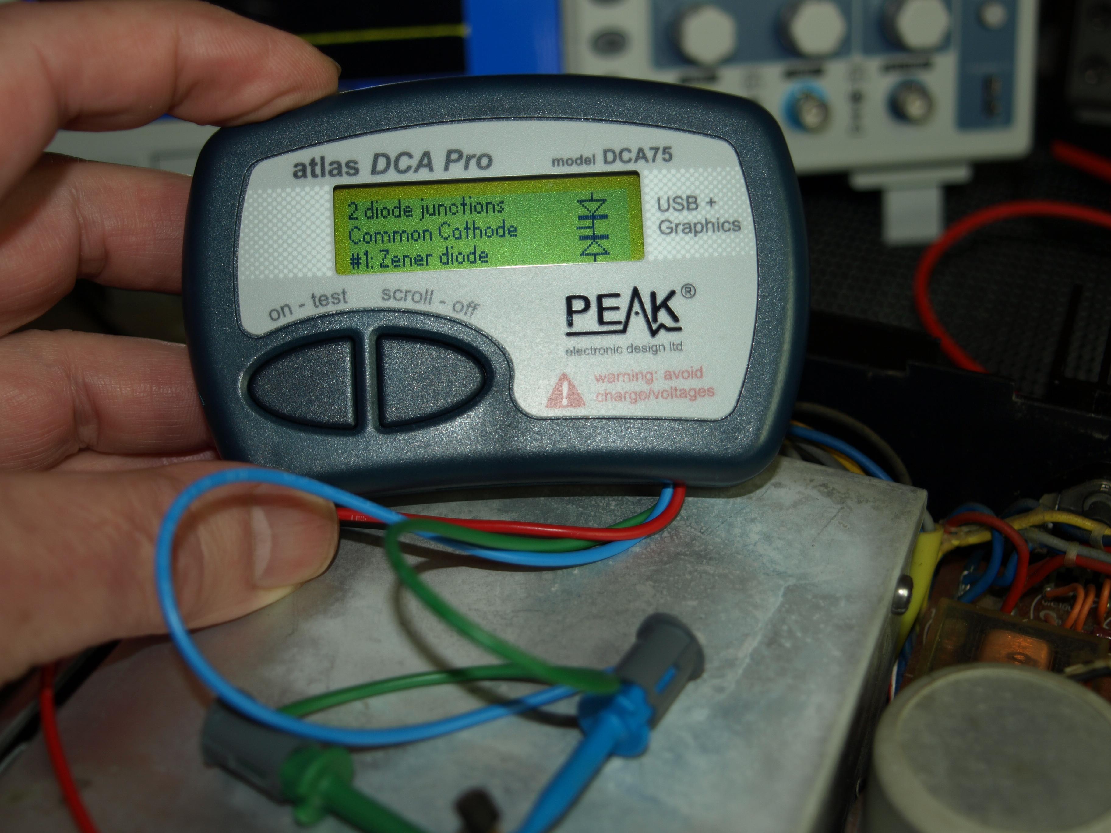
hcraig244SILVER MemberWas TR210 that had gone down….general purpose transistor BC559….changed it out with a BC558 and was rewarded with a working right channel……love that transistor tester.
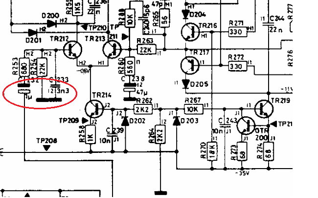
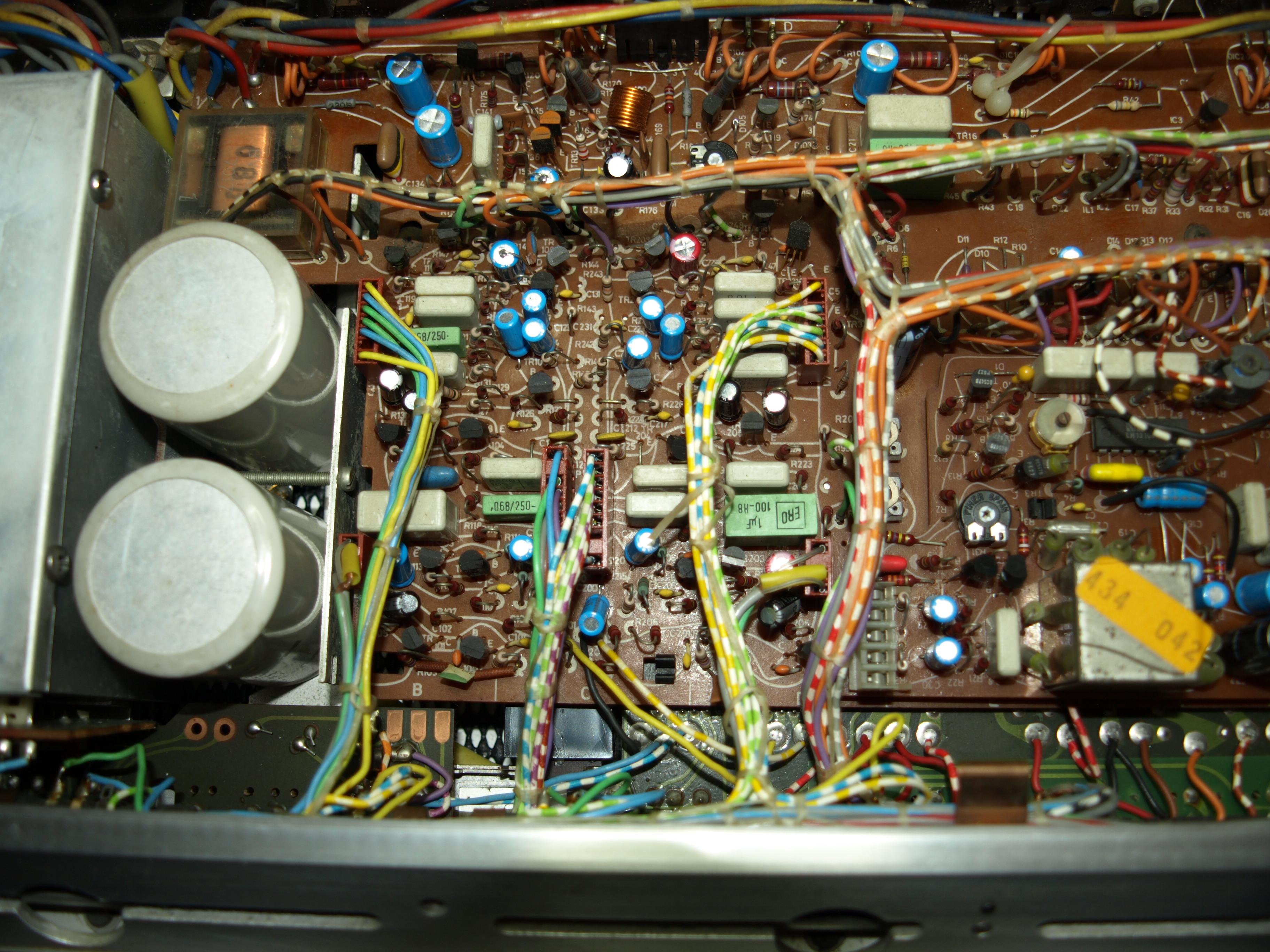
hcraig244SILVER MemberUnfazed by this conundrum i connected up my scope and started to trace the signal path through the right channel….in the past i have connected a signal generator to C200 of the amplifier and checked for the signal at C232 and worked back until i find the signal and replace the defective component….this time i simply plugged an antennae into the set and tuned to a strong signal and using the working left side as a comparison did the same as i would with the signal generator….found this little fellow had failed
 hcraig244SILVER Member
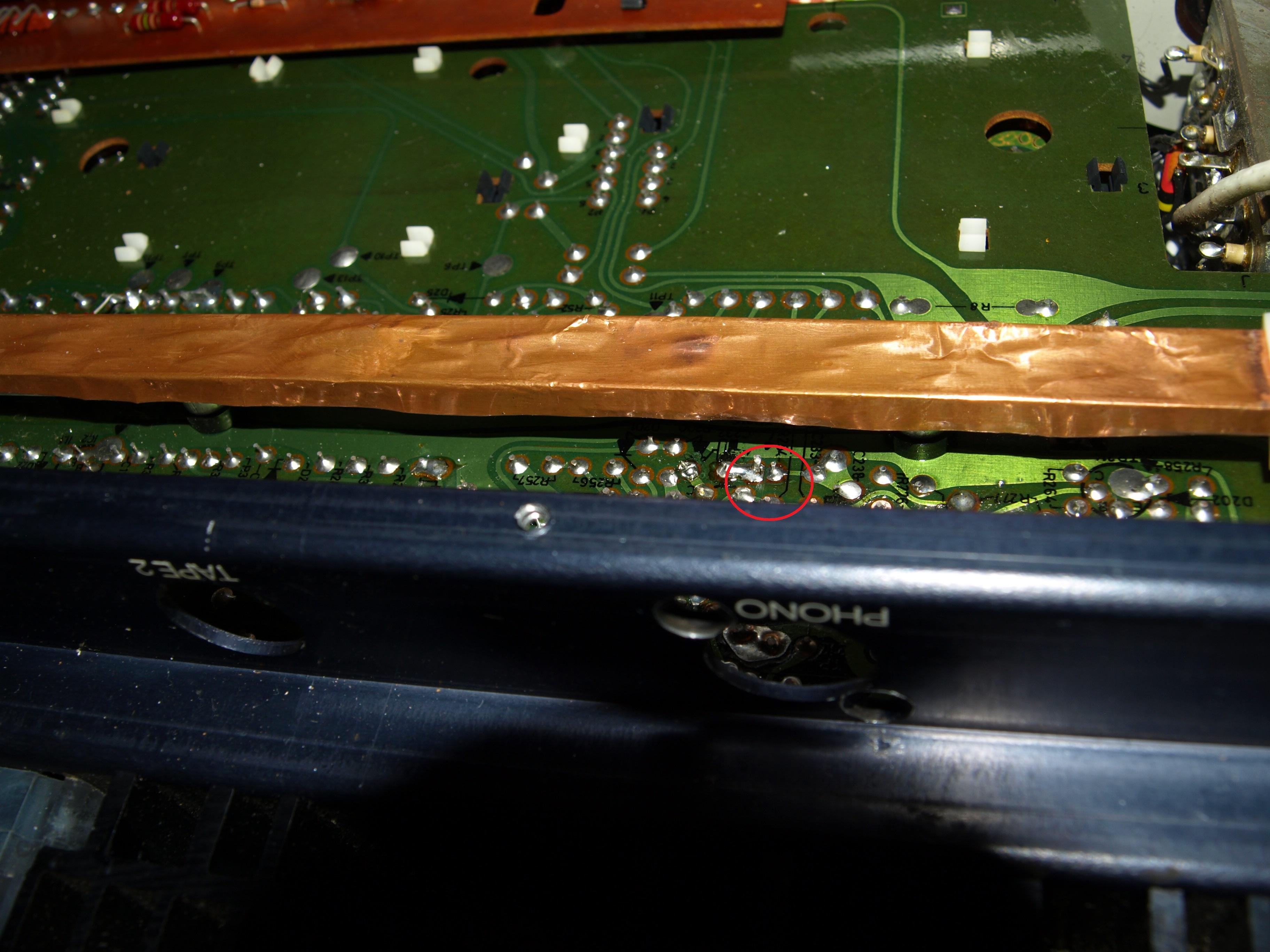
In my defence it is difficult to solder under the support that runs above the components in that area…..I’m unsure why that would cause the working let side channel to go blat, blat, blat rapidly….but when i resolved the issue the left channel came bach to life….Martin can you explain?
 hcraig244SILVER Member
Hmmmm….looks like we have lost a post or two in the transition, not to worry. Repaced most of the capacitors and decided to power up and check everything is good before pressing on, and to my dismay things had taken a turn for the worse!…..the right side channel still didn’t work and the left side made a sound like a wooden stick poked into a bicycle wheel….sort of a rapid blat blat blat noise, very disconcerting. Had to be something i had done…so had a close look at all the solder connections and found I had been a bit to enthusiastic with the amount of solder i had applied to one of the connections…four points had flowed into one instead of only three…
hcraig244SILVER MemberStirling effort so far…….well done!
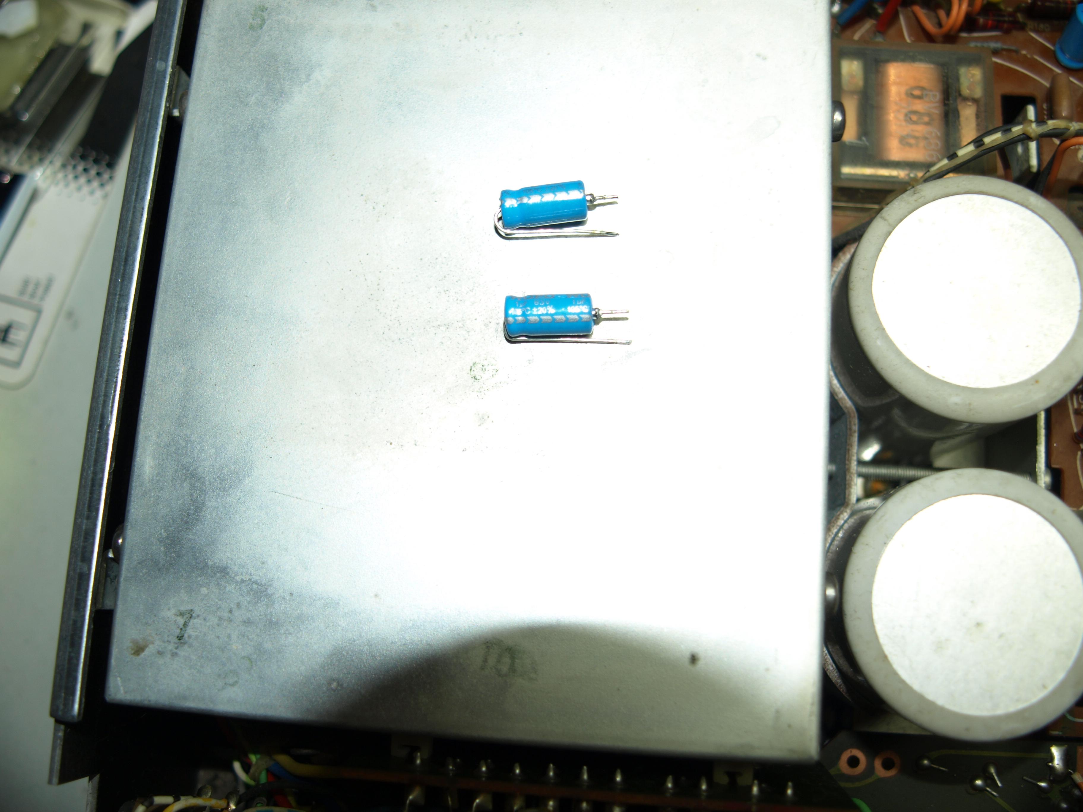
hcraig244SILVER Memberbecause i had cut the tails and installed them they wouldnt go in the correct way around….so had to be replaced, will come in useful another day I’m sure ;¬)
hcraig244SILVER Memberstill getting used to the new site, as you can see….however the work so ar has not been without its excitement….installed 2 capacitors the wrong way around and had to replace them, schoolboy error! can you spot them?
Attachments:
You must be logged in to view attached files.hcraig244SILVER MemberDuring the outage things have moved on……
Attachments:
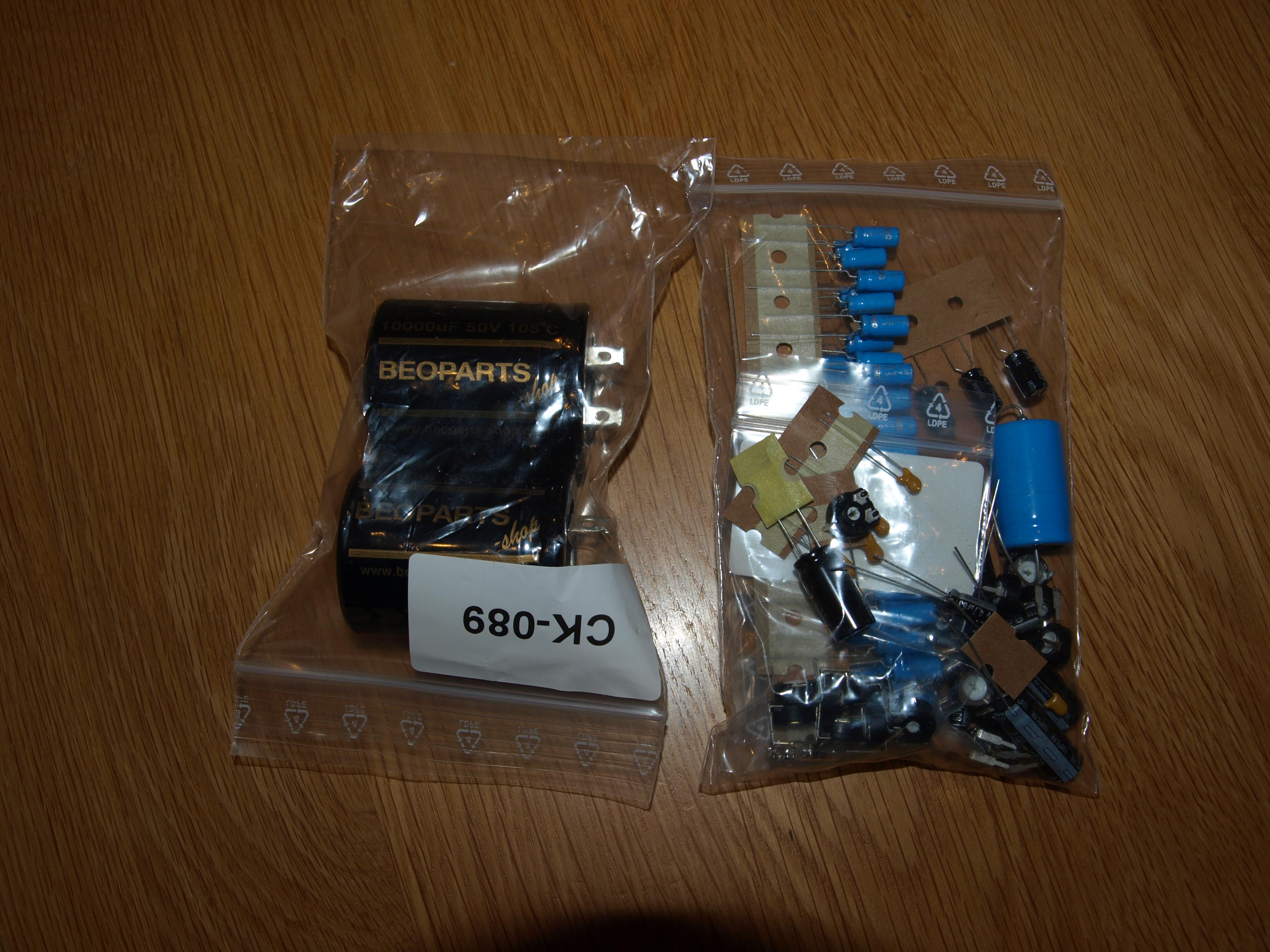
You must be logged in to view attached files.hcraig244SILVER MemberCheers Martin…….buying one of your kits is by far the best way to obtain the necessary parts for a refurb…I’ve tried buying parts myself and although it can be done I ended up placing orders with multiple suppliers to purchase all the parts….and in some cases there is a minimum order level….so you end up with 5 trim pots of a particular value when you only need 1…..and of course the big output capacitors in the kit are custom made to be the correct diameter to replace those made back in the 1970’s……good job Martin ;¬)
Craig
hcraig244SILVER MemberReceived this little lot in the post a couple of days ago…..
hcraig244SILVER MemberException work so far……you should offer to provide those wooden plinths to others, not everyone has access to the equipment required to give such a finish.
Well done
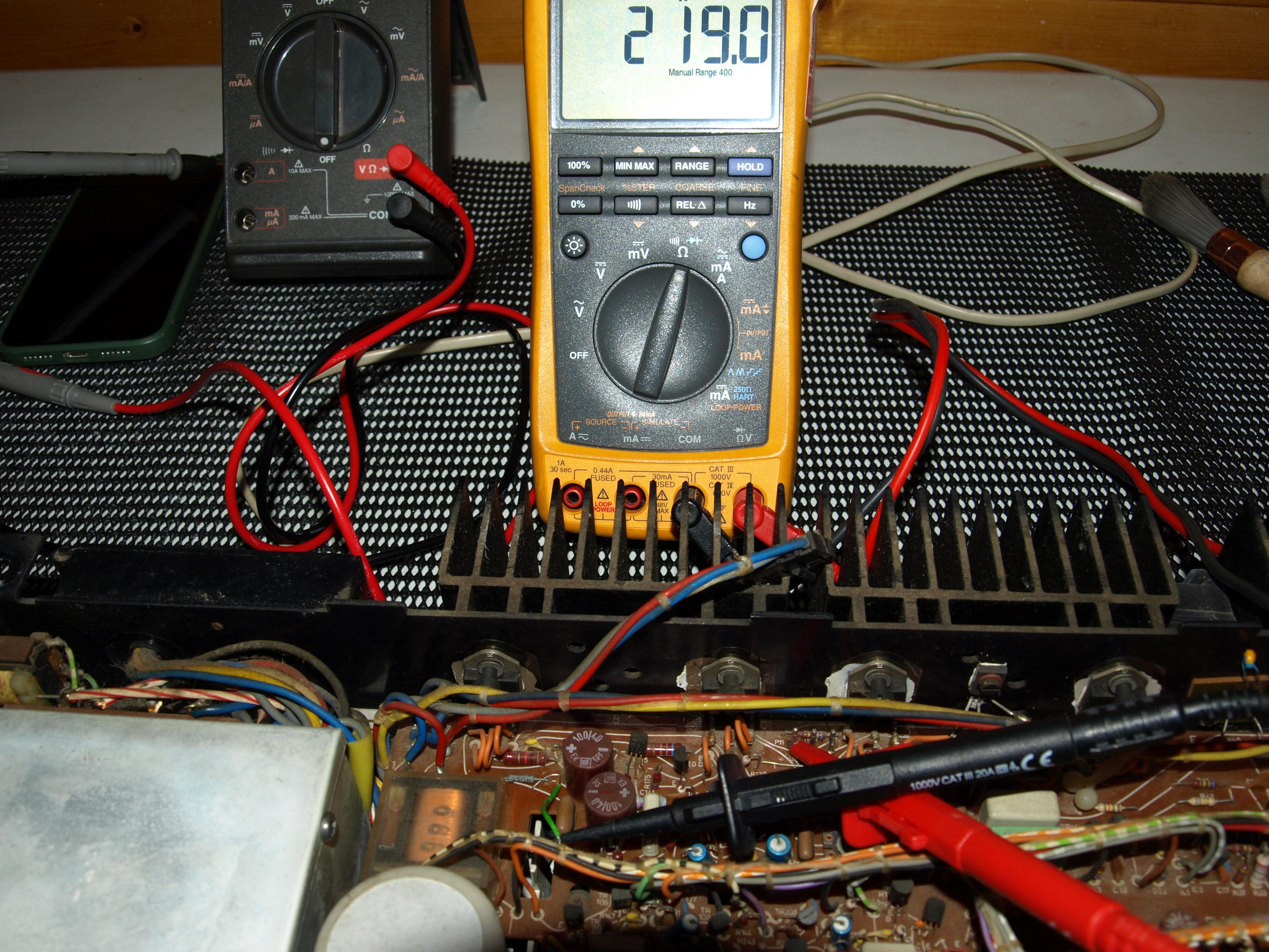
hcraig244SILVER Memberdisconnected plug P11 and with the help o a little piece of wire connected to r168 220 ohm resistor and gave the suspect track break several hard pokes with a blunt stick, reading never budged…..so as I cant see the underside of the board im going to give it the benefit of the doubt for now….im considering running a piece of wire topside just in case….
hcraig244SILVER Memberdiscovered the individual responsible for the cobwebs…at least some of them i’m sure…..
-
AuthorPosts