Forum Replies Created
-
AuthorPosts
-
 hcraig244SILVER Member
Do you have an oscilloscope and a signal generator? I find those two pieces very useful when trouble shooting…..injecting a known signal and tracing it through would bring you to the offending component
Craig
hcraig244SILVER MemberNew one on me…..not came across this before, does sound like a overheating issue….possibly breakdown of the compound applied to the output transistors on the offending channel not providing a good transfer of heat to the main heatsink? I will look forward to the conclusion of this one ;¬)
Craig
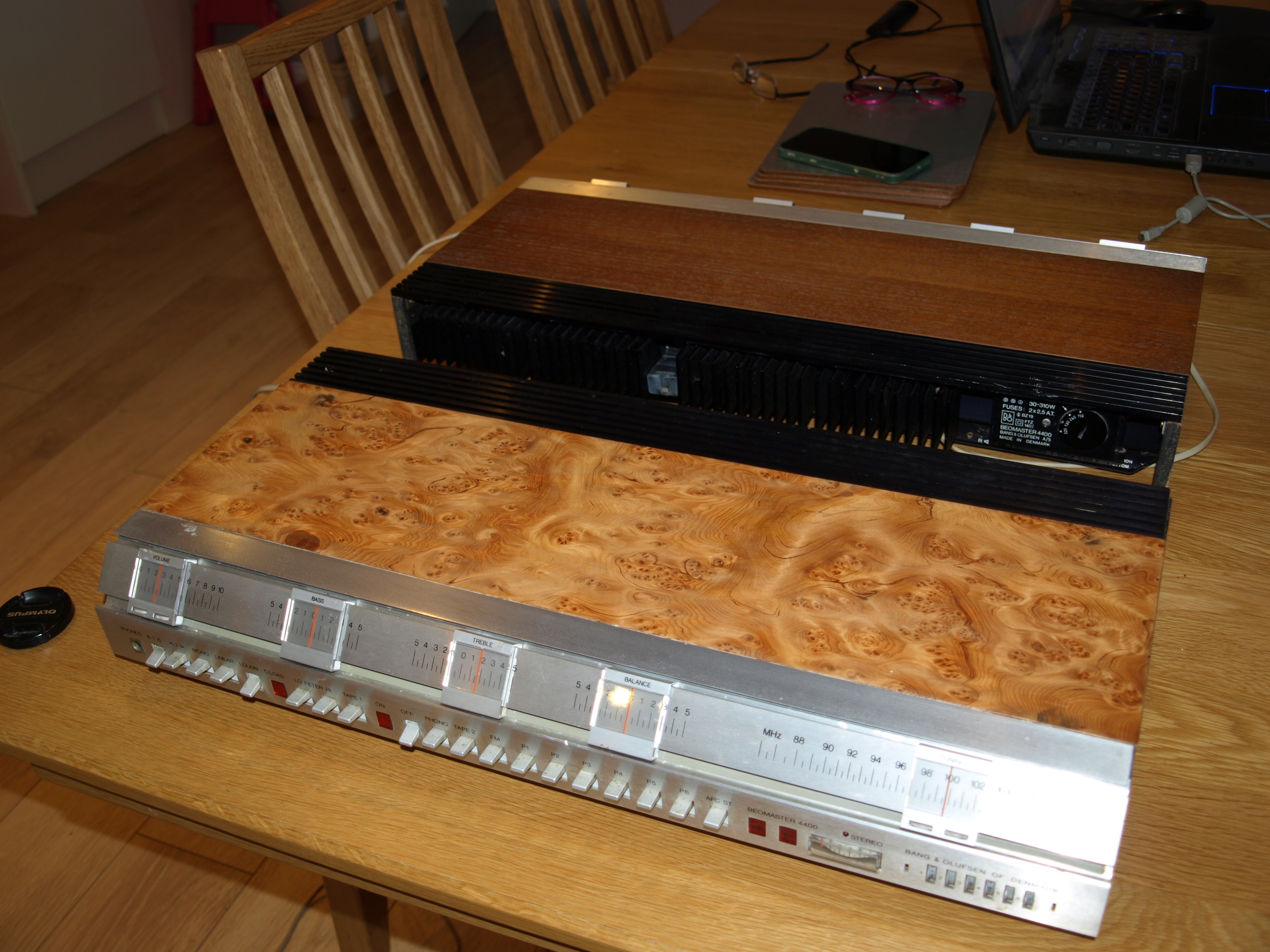
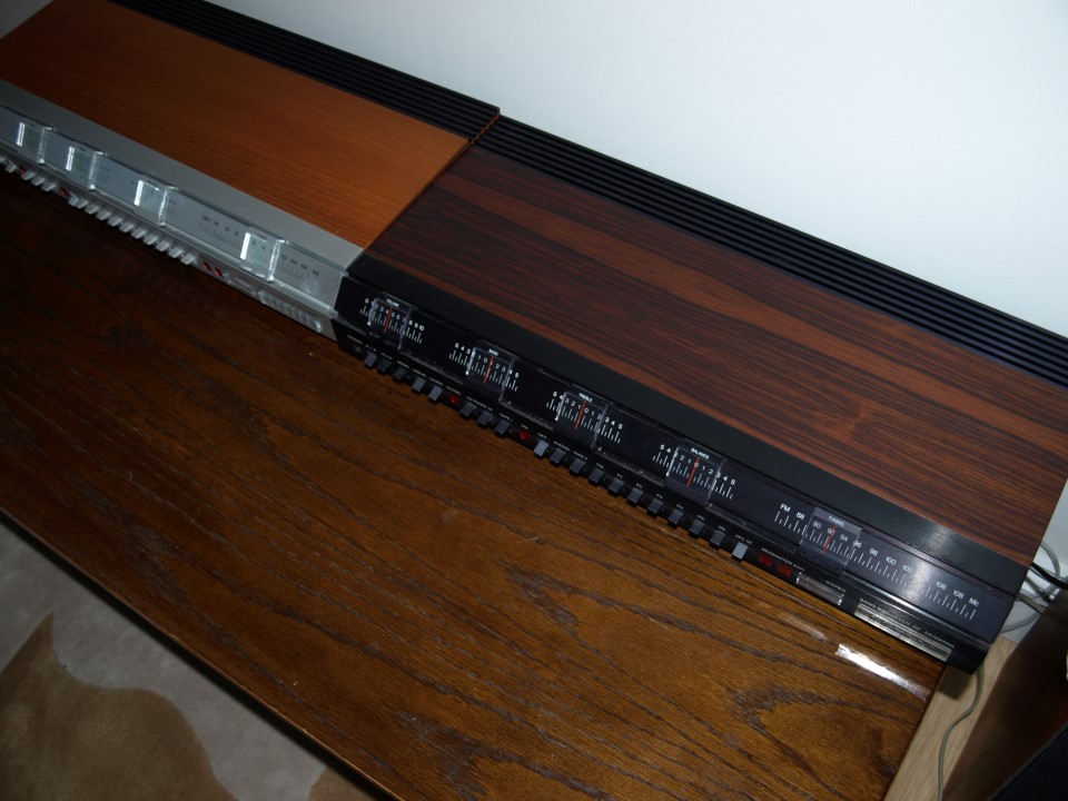
19 February 2026 at 06:40 in reply to: Query about 4400 top cover – grille exposes internals – is this correct? #74045hcraig244SILVER MemberAhh……well, thereby hangs a tale….when I was in the “4400” phase of my addiction I would buy any lost cause that appeared on ebay. I got a lot of pleasure from the repair and restoration of these units and chronicling the progress in the workbench forum of the old site, always received a huge amount of support and advice from the other members. The unit above came to me totally trashed and was described as “requires attention” which made me smile. The electronic repairs to the unit went well but the case ends and top where beyond reasonable repair and had to be completely rebuilt, never having attempted such work I decided to use a “ash burlwood” veneer on top of plywood…..it’s not a perfect finish but I like it. As a result, and unlike most of the others I acquired at that time, I’ve kept it…..
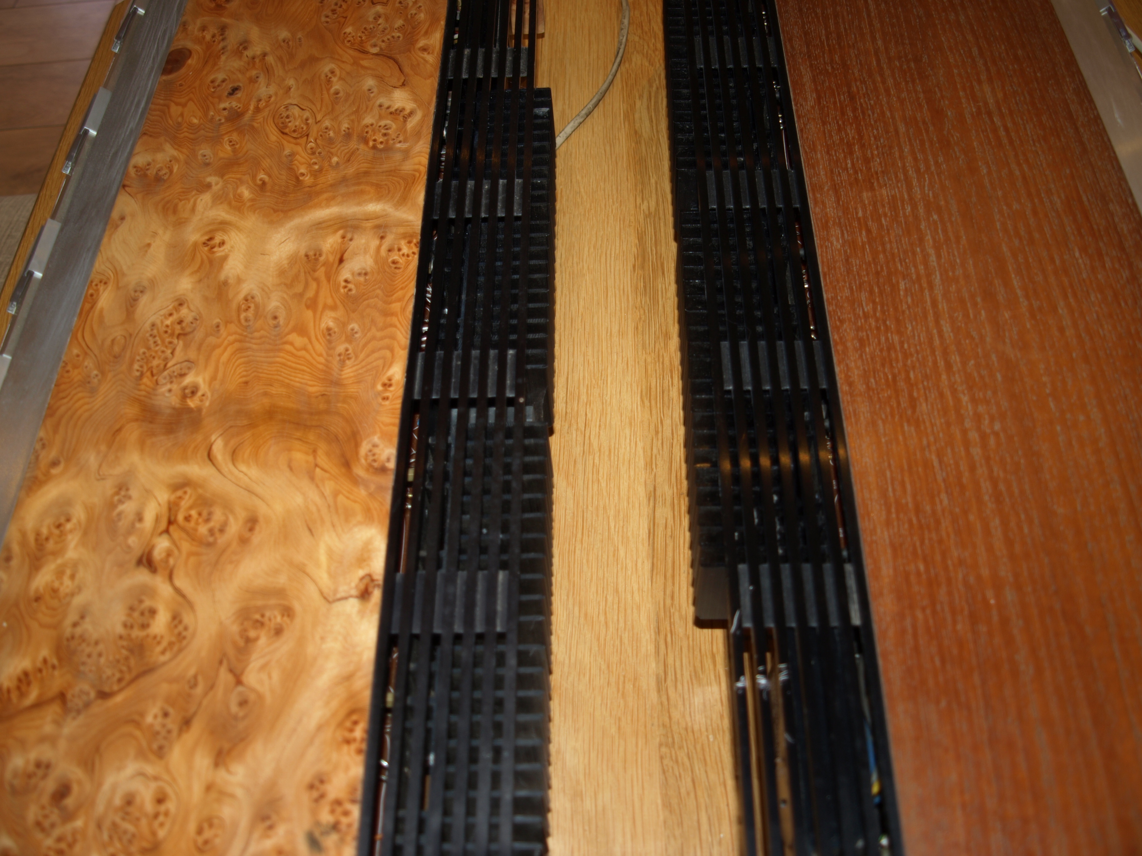
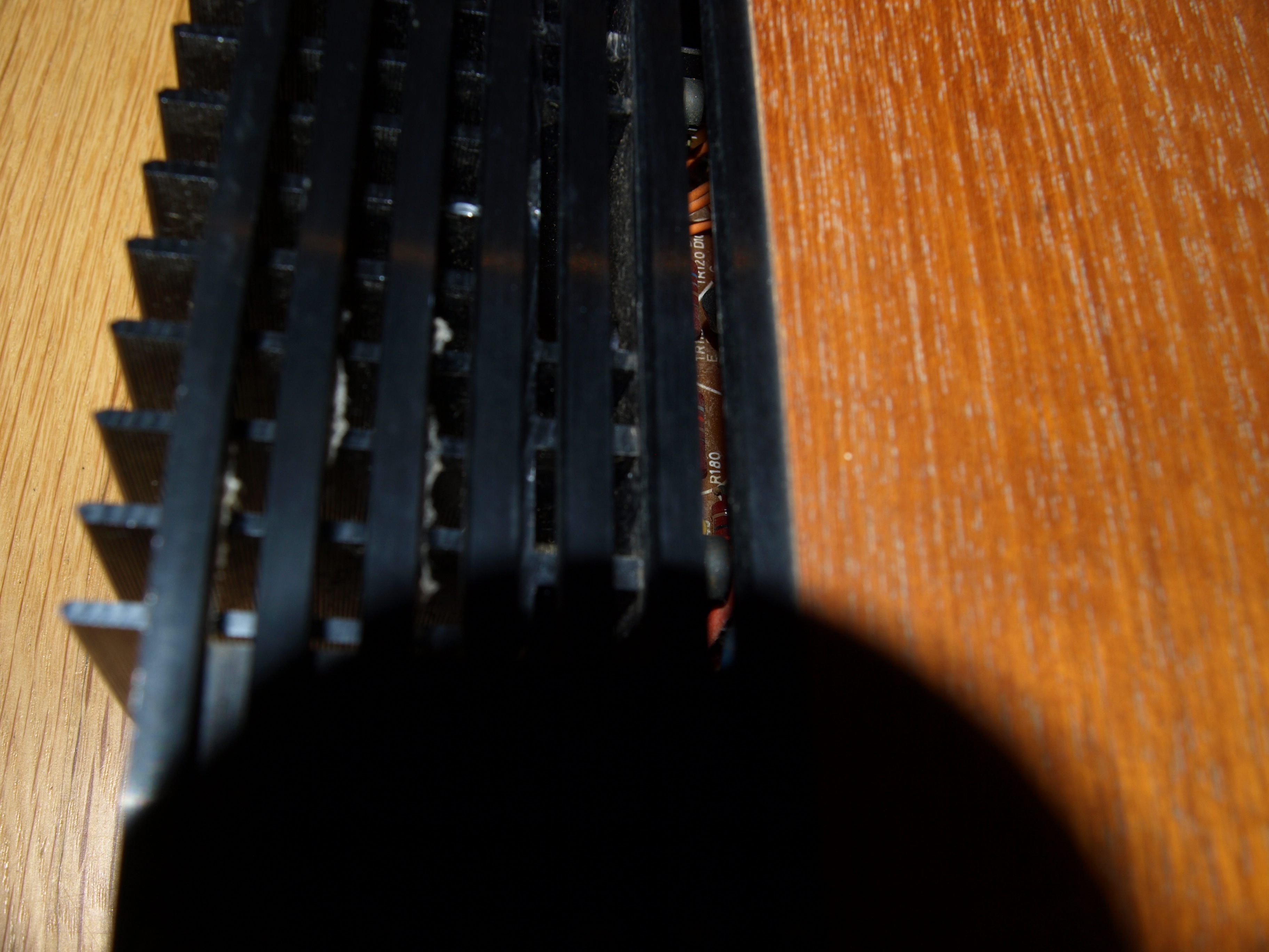
17 February 2026 at 10:44 in reply to: Query about 4400 top cover – grille exposes internals – is this correct? #73917hcraig244SILVER MemberIve still got a couple of these, please don’t ask me why two, and as can be seen both leave ventilation space beyond the cooling fins and into the power amp section….so I would say yours is normal ;¬)
 21 January 2026 at 08:44 in reply to: About to start my 2nd Beomaster 4400 restoration – need tuner restring advice #72749hcraig244SILVER Member
Looking in the manual posted it doesn’t detail the cord arrangements for the unit, if you require any pictures let me know and I will post some in here…..I read the description in the products section or the 4400 and the mention of the 4401 which was described as having almost mythical status….this is a picture I posted 10yrs ago showing a 4400 I was restoring back then alongside a 4401 which was loaned to me for a while for a comparison between the two by founder member Peter…..who still posts here occasionally.
Peter knows of two that exist…..this one and another which may have been sold to someone in Portugal as I recall.
16 January 2026 at 11:04 in reply to: Beomaster 3000-2 Type 2402 15V Power Supply Not Activating #72599hcraig244SILVER MemberUnfortunately powering up isn’t an option untill a proper investigation is carried out, check all fuses (im suspecting blown ones) and power up with the variac whilst measuring the voltages at this regulator…..sadly not got the time right now so not able to provide the information you require….sorry
Craig
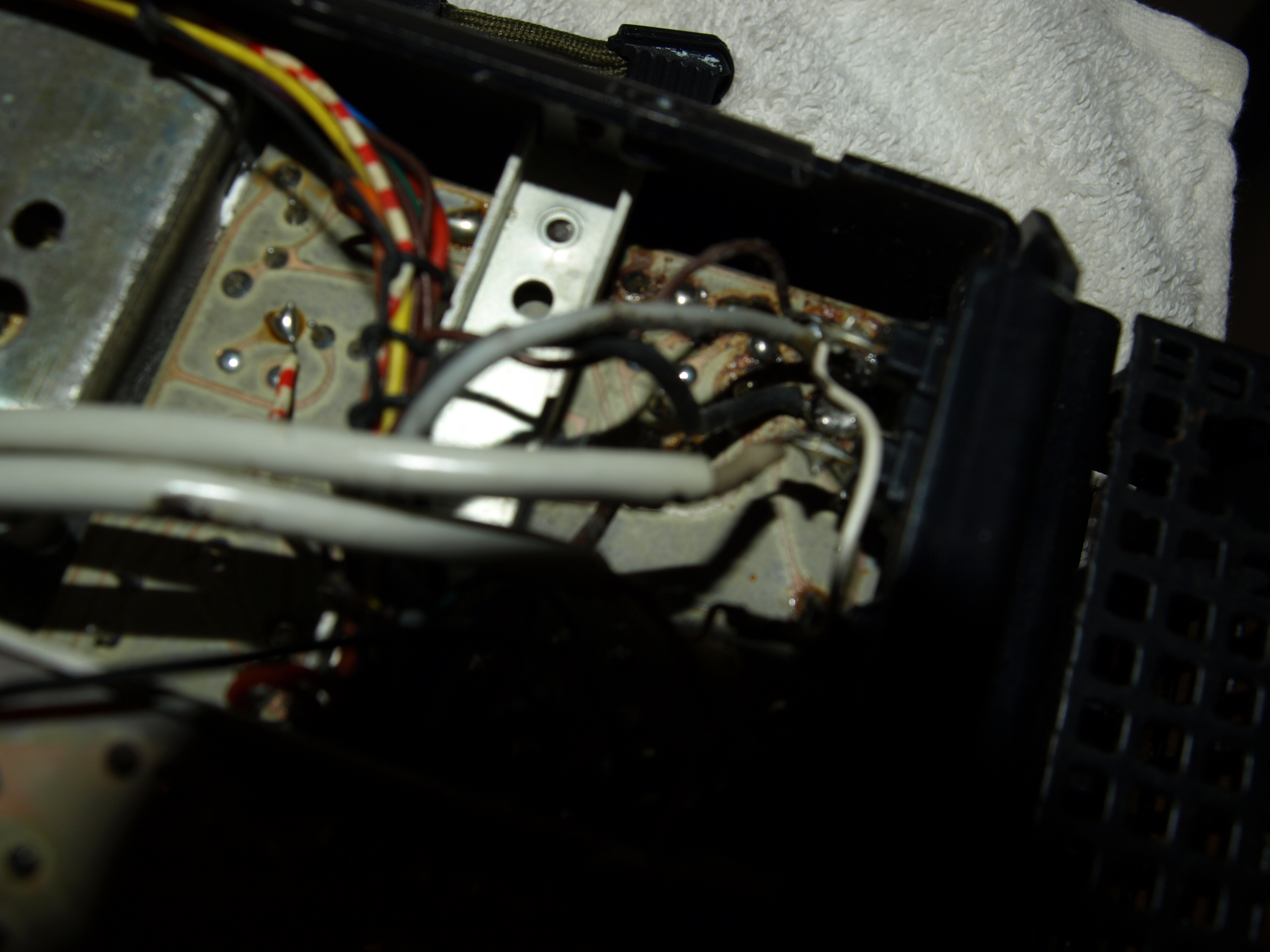
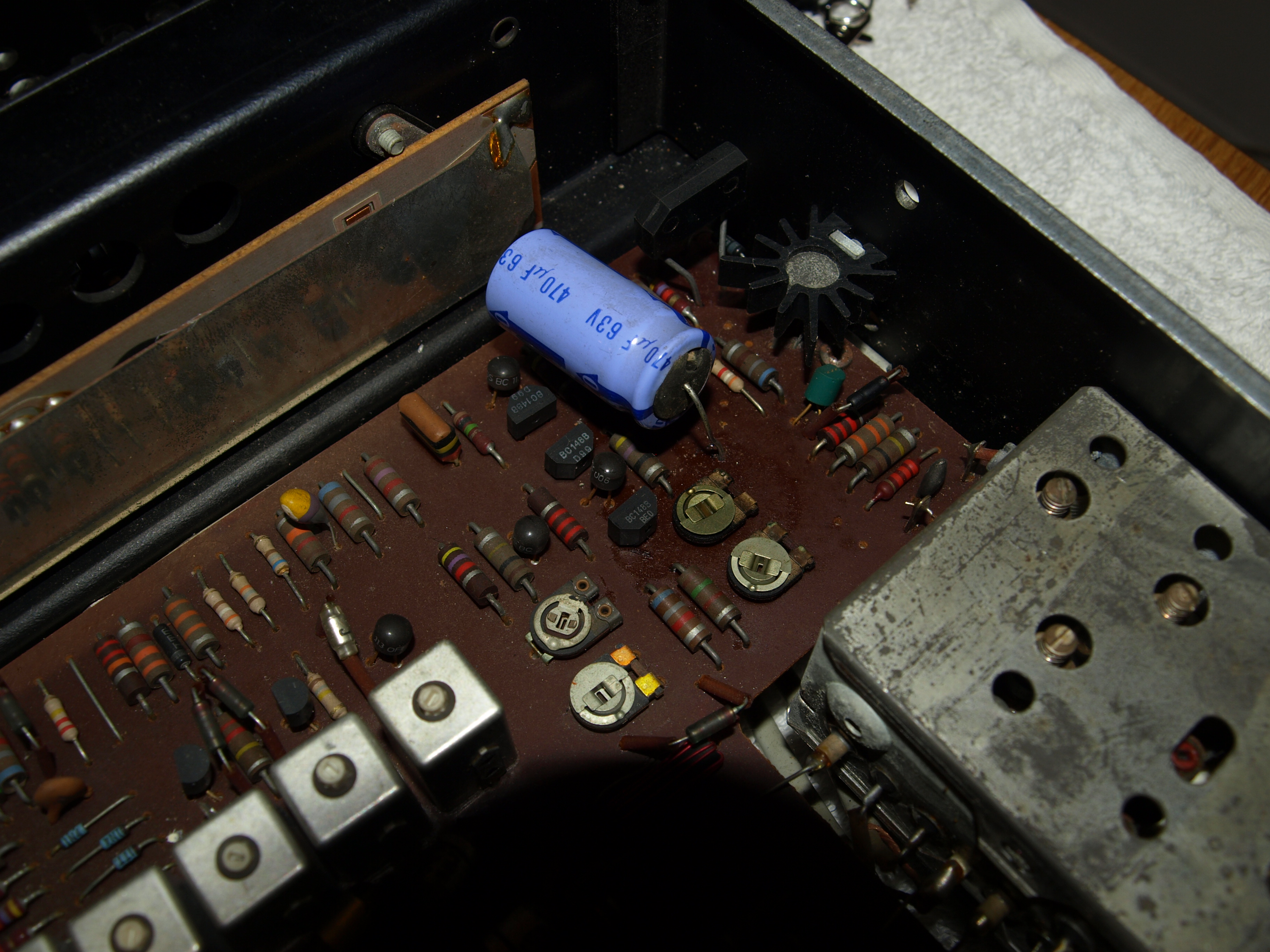
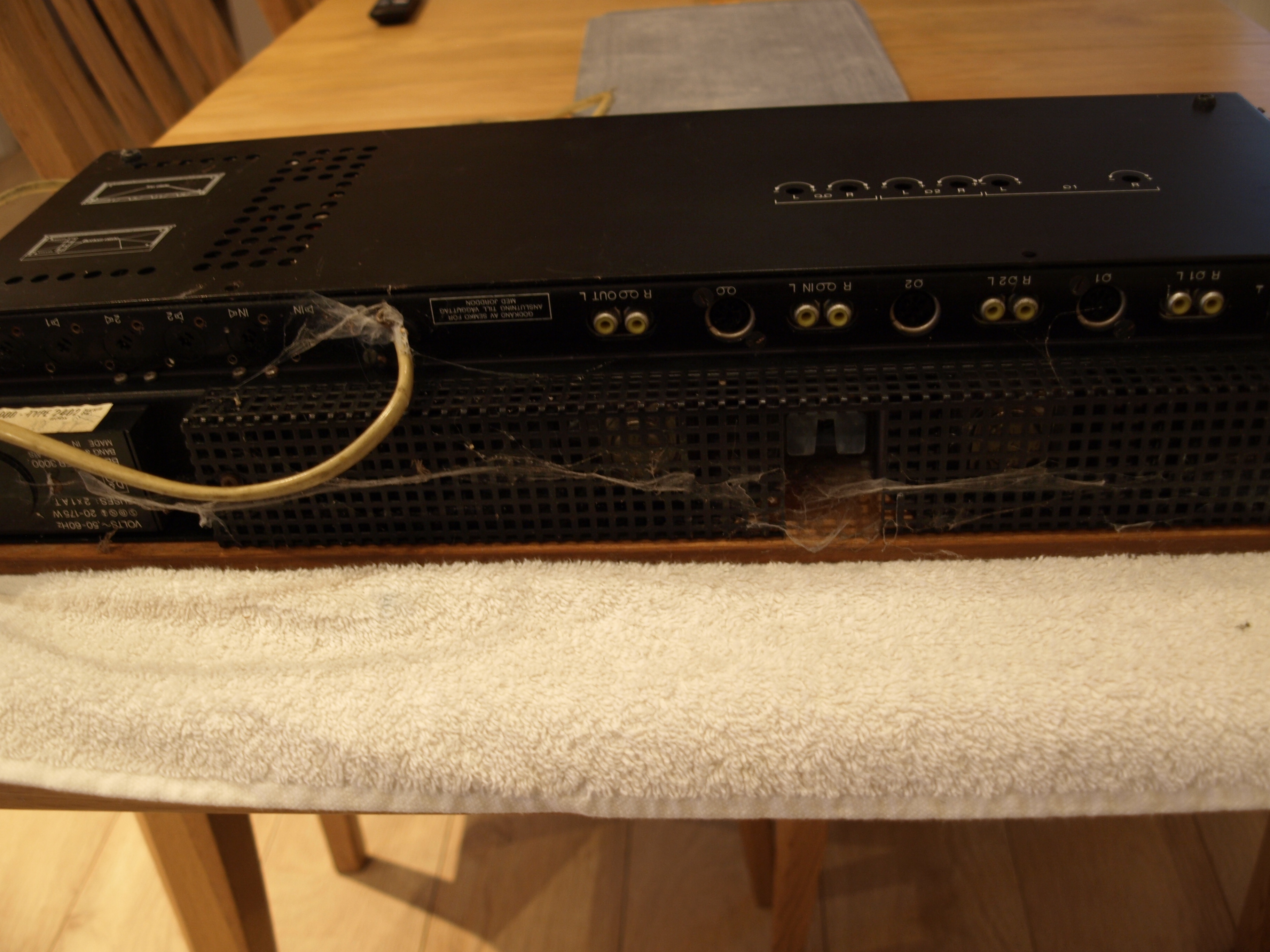
16 January 2026 at 10:59 in reply to: Beomaster 3000-2 Type 2402 15V Power Supply Not Activating #72597hcraig244SILVER MemberA look underneath reveals more potential horrors……
16 January 2026 at 10:56 in reply to: Beomaster 3000-2 Type 2402 15V Power Supply Not Activating #72594hcraig244SILVER MemberDusting out has revealed a probem in the 15v power supply, someone has been here before me and wielded a soldering iron, the smoothing cap that has been replaced has a loose leg!
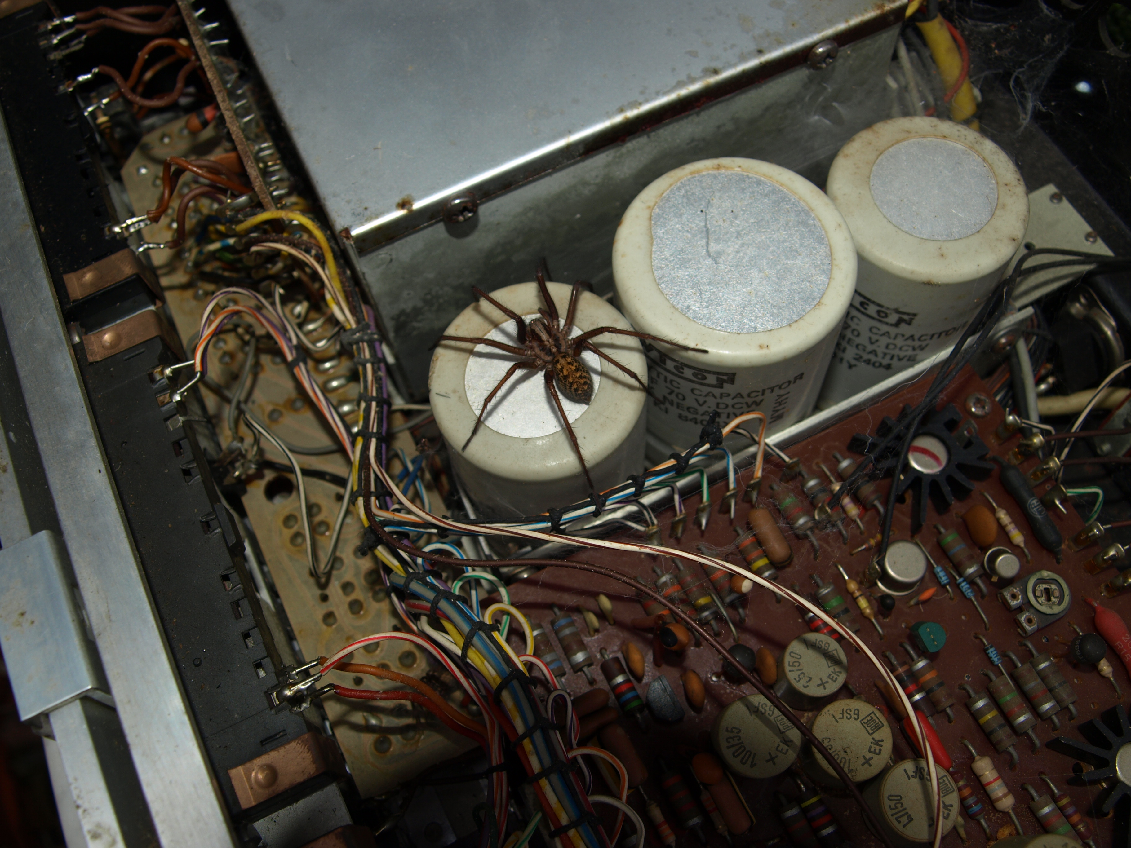
15 January 2026 at 18:17 in reply to: Beomaster 3000-2 Type 2402 15V Power Supply Not Activating #72581hcraig244SILVER Membertook it outside and let it go….hope it doesn’t come back into the house! will have a bit of a clean in here and make sure it all looks well before powering up…..i suspect it wont come to life or I wouldn’t have acquired it.
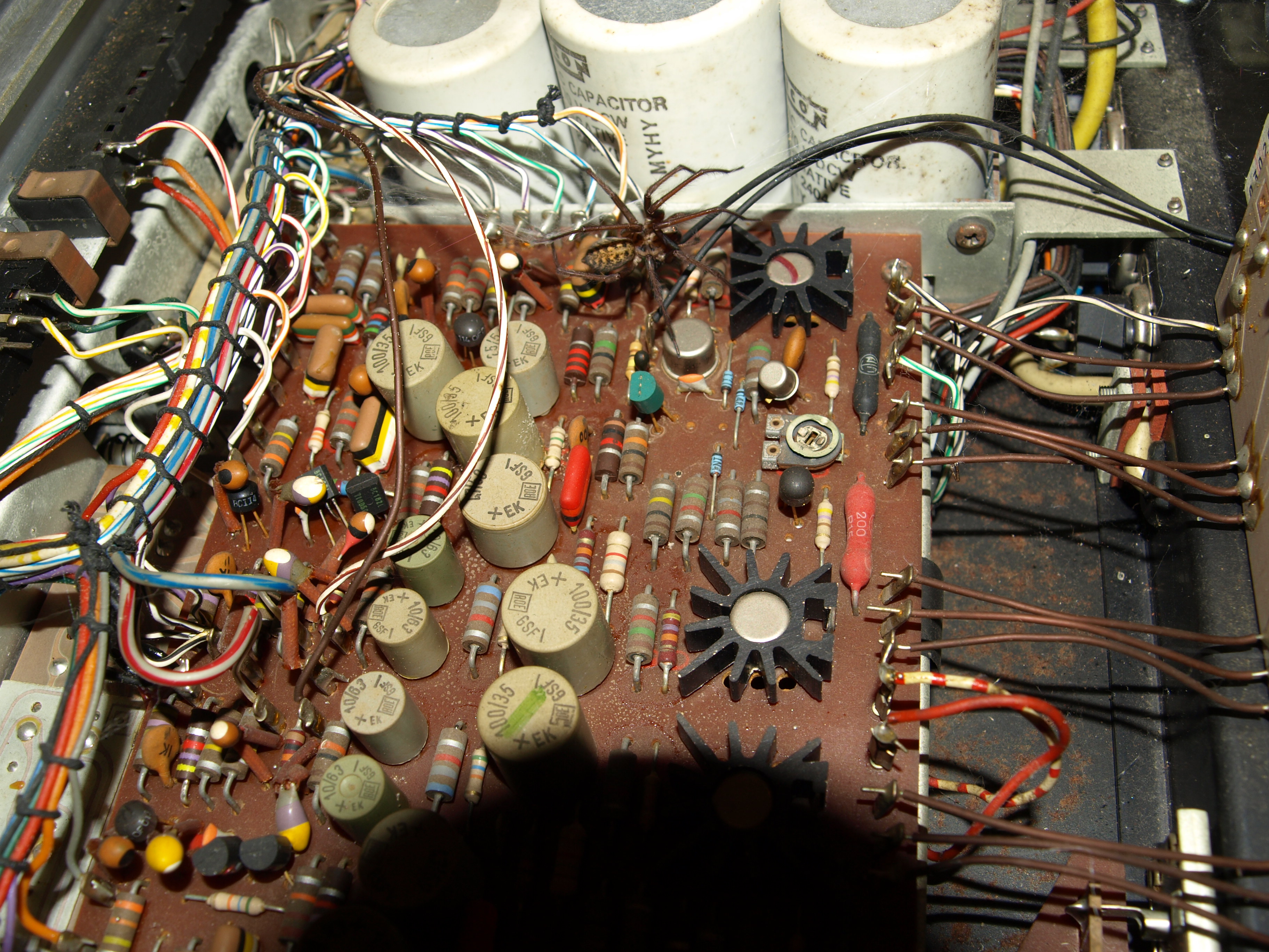
15 January 2026 at 18:14 in reply to: Beomaster 3000-2 Type 2402 15V Power Supply Not Activating #72580hcraig244SILVER MemberLook at this bad boy….
15 January 2026 at 18:13 in reply to: Beomaster 3000-2 Type 2402 15V Power Supply Not Activating #72578hcraig244SILVER Memberlooking inside i discovered I was not alone in there…
15 January 2026 at 17:57 in reply to: Beomaster 3000-2 Type 2402 15V Power Supply Not Activating #72571hcraig244SILVER Memberfound this in the bowels of the workshop, suspected I had one but wasn’t sure…dont even remember acquiring it to be honest!
looks a little sorry for itself…i think I must have bought it several years ago and not got around to it15 January 2026 at 09:59 in reply to: Beomaster 3000-2 Type 2402 15V Power Supply Not Activating #72559hcraig244SILVER MemberI think I have a 3000-2 floating around somewhere…..i’ll have a look for it and if i find it i will take some measurements for you, you’ll need to be specific which points to measure
Craig
12 January 2026 at 08:15 in reply to: About to start my 2nd Beomaster 4400 restoration – need tuner restring advice #72502hcraig244SILVER MemberI thought there was a manual in the products section for the 4400….however when I look I can no longer find it? as I recall it gives the details required to replace the tuner string, I think I have one somewhere and will have a look for you.
Craig
7 January 2026 at 17:57 in reply to: Beomaster 3000-2 Type 2402 15V Power Supply Not Activating #72412hcraig244SILVER MemberProgress…..I have also found a number of instances where the circuit diagram has been in error….I always take pictures of the units I work on before disconnecting or replacing items, I have also found instances where the actual markings on the PCB have been wrong.
You should replace all of those skeleton trimmers as soon as possible…if they let go you can blow your output transistors…and after all these years they are quite fragile…encapsulated trimmers are easy to obtain…a good idea would have been the purchase of a kit from dillen which contains all the recommended replacement components ;¬)
Craig
hcraig244SILVER MemberCheck out these two links….there are a couple of different designs….
https://beolover.blogspot.com/2020/08/beogram-4000-mmc-cartridge-mount-replacement.html
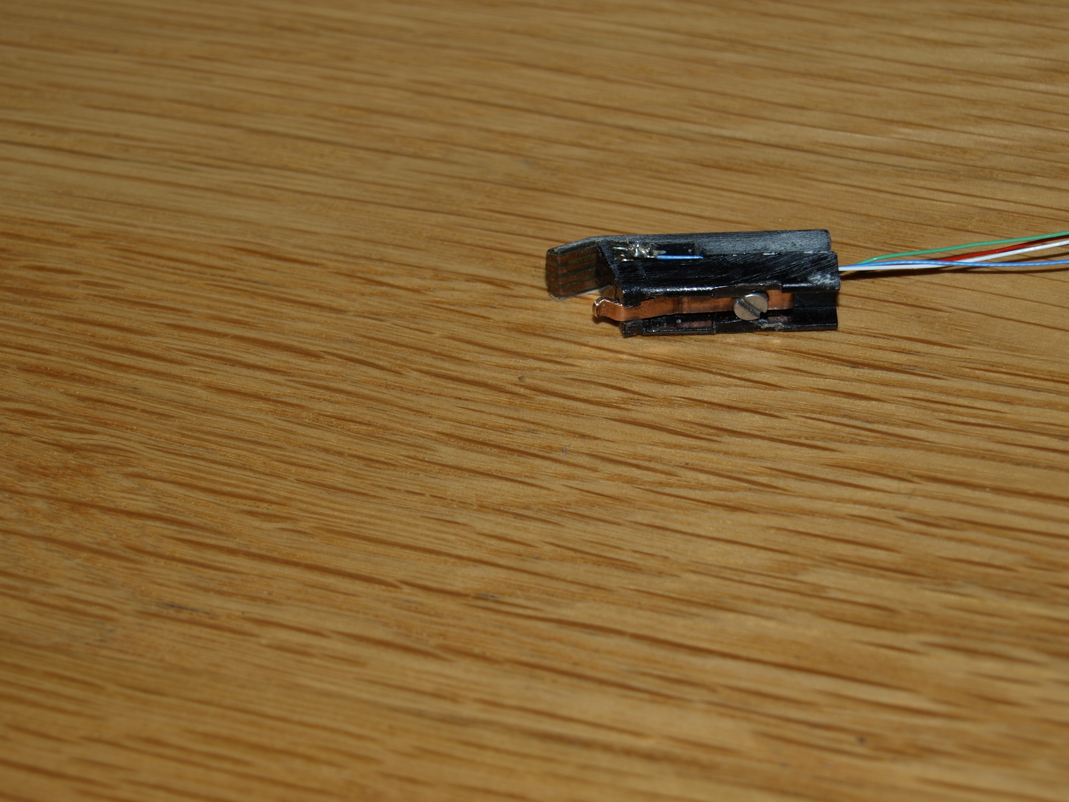
hcraig244SILVER MemberBe very careful when removing or installing the cartridge, the plastic connector will be very brittle and susceptible to fracture, many have suffered this fate. As Mark says it looks very much like the cartridge isnt seated correctly on the grounding tab (copper spring that grounds and also helps keep the cartridge in place) make sure the slot at the bottom of the cartridge is free of any debris. These arms can be repaired however its a fraught excercise that requires a degree of destruction prior to rebuild, and of course purchase of custom 3d printed parts, available from Rudi at a cost….dont bend the copper spring, is meant to be shaped to fit….there is a distict “click” when the cartridge is fitted correctly.
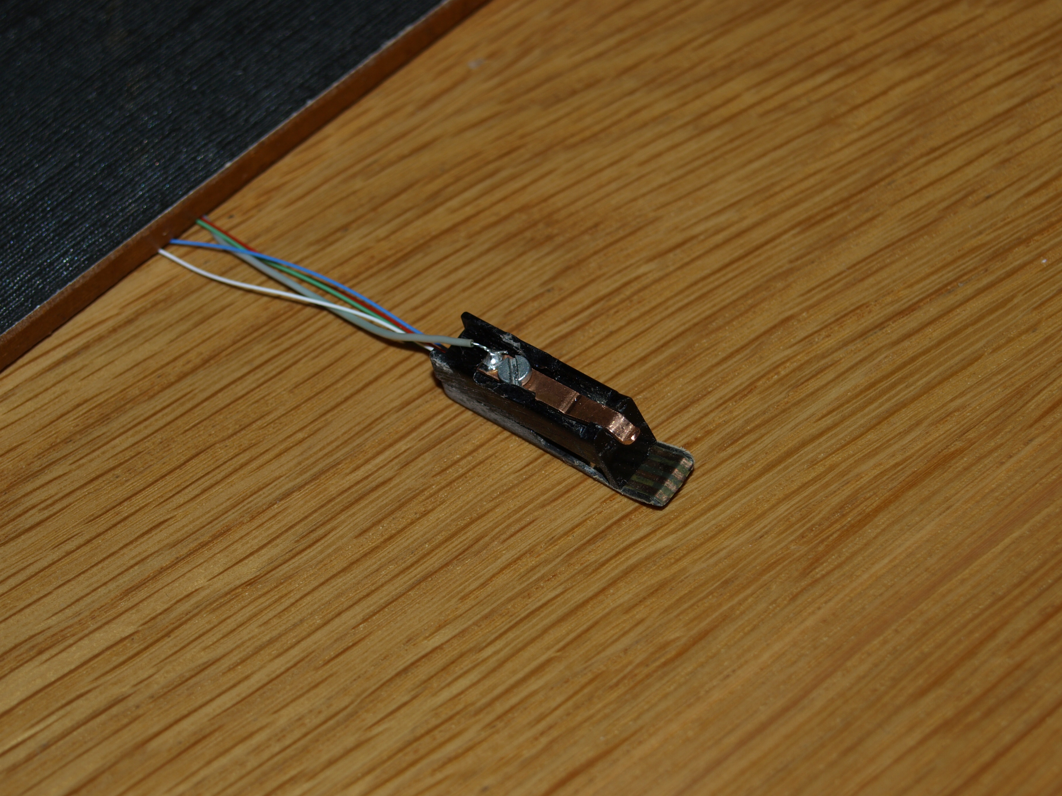
This is one i repaired with a 3d print and self fabricated spring…
Should fit like this…..hopefully you only need to align yours correctly and it will ir snugGood luckCraighcraig244SILVER MemberI have been involved in a good number of BG4000 repairs/restorations over the last 10 years or so…..the two in my possession where purchased as spares or repair over 7 years ago for around £150. I spent perhaps £60-£100 on parts, components etc on each…and in one case many hours chasing down an intermittent fault that ate my lunch for weeks….I also relied on the expanse of knowledge and support from the members on this site. I now see, as everyone else on the site, the same decks offered….and in some cases sold, for eye watering prices. I actually think the decks are worth these sums once repaired and fully functioning, the 4000 is massively over engineered and the means by which the end has been achieved by B&O looks to be the most complex and complicated procedure imaginable given the technology of the day…. to introduce a deck of the same quality and engineering excellence into todays markets would be prohibitive, as can be seen by the price tag placed on the 4000C upgrades offered currently……..for some of us its not an investment/earning opportunity its more a passion for quality.
Personally I prefer the 4000 series over the 4002 due to the inherent complexity of the machine, this does however bring with it the regular hiccup’s associated with such old equipment….which most of us actually enjoy resolving…for me you should consider your motivations before shelling out £1,700 for a potential return down the road.
Craig
hcraig244SILVER MemberPost a couple of pictures…..may help diagnose the problem for you
Craig
22 December 2025 at 12:50 in reply to: Beomaster 3000-2 Type 2402 15V Power Supply Not Activating #72058hcraig244SILVER MemberThis is where a signal generator and oscilloscope come in real useful, you can track the signal path through the circuit until you pick up the distortion…….not much help I know 😳
-
AuthorPosts