Forum Replies Created
-
AuthorPosts
-
 GlitchBRONZE Member
Were the schematics for the Beolab 1 ever released?
It seems like the need for secrecy, for both the OEM and secondary repair businesses, has long passed.
garibaldi70: In your 8845 picture, it appears like the corrosion may have eaten through the copper traces. Cleaning these with something like a scratch pen would be one of the first steps in debugging. This kind of repair, and Class-D amplifiers in general, can be difficult if you don’t have the proper equipment.
Glitch
14 August 2024 at 14:45 in reply to: beomaster 1000 ( type 2317 ) restoration & improvements? #58277GlitchBRONZE MemberWhat software are you using to parse the signal & generate those graphs?
I use a dedicated audio analyzer and use the software included with it. Prices and quality of audio analyzers vary greatly. Testing with general purpose test equipment and post processing the results is also a viable alternative. The price and quality of the general purpose equipment also varies greatly. What is more important than the price/quality of the particular equipment is that one understands the limitations of it and uses it accordingly.
Have you ever gotten a flat result out of a RIAA preamp circuit?
Everything is flat if you zoom out enough. Nothing is flat if you zoom in enough. I don’t worry that much about the “flatness” of vintage equipment. The “tonal coloration” of the old equipment is part of the charm that makes it interesting. I concentrate more of having the left and right channels match.
Maybe by the time I get this rebuilt I’ll try analyzing some parts of the circuit like that.
I try to repair the equipment just enough to get it working reliably. This usually consists of fixing the broken solder joints on the edge connectors, ensuring that the power supply voltages are correct, and adjusting the bias currents. I then do a baseline performance test (i.e. the “before” test). You can learn quite a bit at this stage. Sometimes this test reveals a specific issue that needs to be fixed. Other times, it reveals that a 60 year old piece of equipment is remarkably close to its original performance specification. It is much easier to do the “before test” before you swap all of the capacitors ;-).
Glitch
13 August 2024 at 20:10 in reply to: beomaster 1000 ( type 2317 ) restoration & improvements? #58254GlitchBRONZE MemberThe curves above are for just the RIAA stage.
You are correct in thinking that adding more stages would complicate any analysis. Testing smaller subsets also allows one to tailor the test to the component being tested. For example, testing the power amp stage is a quite different test than testing the RIAA or pre-amp stage.
I prefer to be data driven when doing repairs and modifications. I don’t think that there is anything particularly wrong with the swap parts and listen methodology if one likes the results. I just think that I reach my goals more quickly and with more confidence with test data.
Glitch
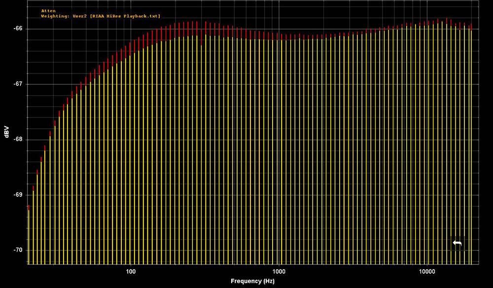
13 August 2024 at 13:52 in reply to: beomaster 1000 ( type 2317 ) restoration & improvements? #58243GlitchBRONZE MemberThe green/red colors are for the left/right channels. The test is of a series of (nearly perfect) RIAA weighted sine waves being fed into the circuit board and the output measured. Each vertical line is the result at a given frequency. All of the bars at the same height would indicate that the circuit perfectly implements the RIAA curve.
The deviation from a flat response is the “tonal coloration” of the circuit. Differences between the green and red curves indicate that each channel has a different coloration.
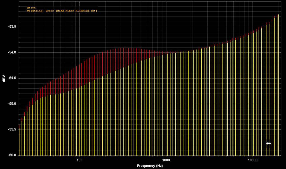
This kind of plot can really highlight differences between circuits or issues within a given board. For example, the second plot was for a board that was recently recapped using fresh, high quality Panasonic electrolytic capacitors. This shows that you can’t just blindly swap parts and expect perfection. There may be variation in the new parts or another underlying issue in the other components. Another example would be if someone suggested component values based on the first circuit and you were working on the second circuit. I wouldn’t even want to try to guess what the final result would be.
Glitch
12 August 2024 at 17:34 in reply to: beomaster 1000 ( type 2317 ) restoration & improvements? #58202GlitchBRONZE Member

The above plots are of the “deviation from ideal” for the RIAA amps of two different Beomasters. Areas of “improvement” could be to better match the curves to the ideal curve, make the left and right channels match better, or try to match the curve to a particular cartridge. Regardless of what your goals are, one will need a way of measuring the circuits to know if you achieved them.
Glitch
7 August 2024 at 15:03 in reply to: BeoLab 8000: Broken plastic leg supporting PCB > which glue ? #58090GlitchBRONZE MemberThe 3D printed part is a great solution!
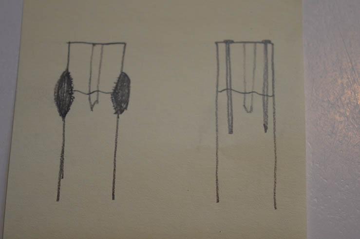
If you still want to try repairing the old part, a stronger glue, added reinforcements, or a combination of both might work. Below are a couple (of many ways) to do this.

In the first picture. The outside of the post is roughed up so a mechanical bond with the glue can be made. My favorite glue for this type of repair is original JB Weld. In this repair the epoxy itself provides all of the strength.
In the second picture, metal pins are heated and pushed into the plastic. The melted plastic holds the pins in place and the metal provides the strength. Another option could be to glue a thin walled metal tube over the post.
For any repair, be sure that you clean out any material that may have gotten into the screw hole. Lubricating the screw can also reduce the stress on the repaired part.
None of these options will look as good as the 3D printed part, but once the speaker is reassembled nobody but you will know.
Glitch
GlitchBRONZE MemberErik,
The drawer is primarily held in place by the belt and drawer motor. The motor’s resistance to turning, along with the mechanical advantage of the belts and pulleys, keeps things in place. One can still open the drawer manually by back-driving the motor. I would start debugging this by replacing the belt. A loose, slipping belt would result in the behavior that you are describing.
Glitch
GlitchBRONZE Memberit seems a big coincidence to me that one is xxx19 and the other xxx18, but maybe I’m thinking too much! Pictures below.
Maybe it is as simple as the serial number starting index from zero and the edition number starting index from one.
Glitch
GlitchBRONZE MemberIn the Beolover blog, he writes: “Here is the keypad received back from being professionally coated, this new coating is more permanent – very durable and cannot be removed chemically (by cleaners, etc), and it’s also an excellent match for the frosty appearance:”. However, the exact specification of “profession coated” is not stated. This could be any number of things like powder coat, epoxy, two part urethane, etc. The level of gloss (i.e. flat, satin, semi-gloss) is also missing.
Does anyone recall any mention of the missing details?
This information would be invaluable to those that don’t have multiple keypads to experiment with. Also, considering that the parts are becoming increasingly rare, it would be a shame to lose some to unnecessary experimentation.
Glitch
GlitchBRONZE MemberIs there a way to bypass or clean/recondition the muting circuit switch?
One way to debug mute relay/switch problems is to simply remove (or disconnect) the mute relay/switch. The mute relay/switch grounds out the L and R signals from the cartridge. Without it in the circuit, the phono should still play music (if the problem isn’t something else). Removal also makes it easier to test continuity of the traces/wires between the cartridge and the connector on the back of the phono.
Replacement of the relay/switch is preferable to cleaning. If a replacement isn’t available, cleaning should be done with the least aggressive method that yields results. Of course, cleaning is easier with the part removed.
Glitch
GlitchBRONZE MemberOn jpoliv saidIs it possible to polish?
Technically, yes. Practically, no.
I believe that the finish on that is polished aluminum with a clear anodized coating. The anodizing is a very thin, hard, protective layer that is scratch resistant and eliminates oxidation. Any attempt at polishing would likely remove this layer before removing the scratch.
So technically, you could simply polish the panels. However, they would only look good for a short time before the getting scratched again and becoming dull from oxidation. This would start an endless cycle of constant polishing.
The recently polished panel could be top coated with something to protect it. The best choice for this is clear anodizing (which is not a DIY finish). There are many clear spray finishes that could be applied, but it won’t look the same as original.
Personally, I would just live with the scratches. If they really, really bother you… Buy a nicer, pristine example of the same piece of equipment. The cost of the new equipment could be offset by selling the scratched one and the money you saved by not messing with scratch removal.
Glitch
p.s. You can verify the finish by lightly touching the panel with a multimeter measuring ohms. The anodized layer is electrically non-conductive.
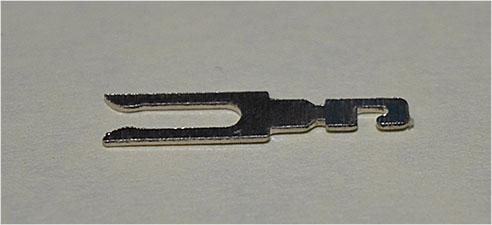
GlitchBRONZE MemberFYI, that particular pin came out of panel mount, 2 pin DIN, female connector. These still seem to be reasonably easy to buy, but are of questionable quality. I agree that finding a NOS solder-able part is a long-shot, but I’ve been surprised before by what I’ve found for sale. I think that any possible solution is going to involve creativity, ingenuity, and some quality time with jeweler’s files.
Trying to look at the bright side, the pins from the panel mount connectors have the right the “business end”. The material between the pin fork and what gets soldered to the board is less critical.
On a similar subject, I’ve been thinking about replacing the 3 and 4 pin DIN speaker connectors with “something else”. Considering that the male versions of these connectors are essentially unobtainable, there appears to be a need here for those that are trying to keep the old equipment going. I assume that I’m not the first to consider this. If a solution exists, it would also solve the worn-out 2 pin connector dilemma.
Glitch
GlitchBRONZE MemberGuy: That explanation makes sense. Thanks!
pilatomic: I found a similar speaker connector on my bench. A picture of one of the pins is shown below. HTH.

Glitch
GlitchBRONZE Memberpilotomic: I had a similar issue with a different model Beomaster. The pins in the speaker connectors were worn to the point that they didn’t make good contact. I was not able to find the same style connector as a new replacement. My solution was to buy a different style, board mounted, speaker connector and swap the pins from the new connector into the original connector.
Another possibility is to remove the pins from the old connector and squeeze the pin tips together. I would see this as more of a temporary solution.
I probably have some pictures that would make the above descriptions make more sense. Let me know if you need any additional clarification and I’ll try digging through my photo archive to find them.
As far as the mute relay goes… Do you have any idea why B&O would only mute Speaker1 and not Speaker2 in the BM5500?
Glitch
GlitchBRONZE MemberFilipe: Do your Penta’s switch between standby and “on” (i.e. red to green LED)?
I don’t leave my Beolab Penta’s permanently connected to the mains. While I agree that they were designed to be plugged in all of the time, they are ~40 years old.
I make it a general rule to connect vintage electronics via a switched and fused power strip and keep them totally powered off when not in use. This helps protect the equipment from things like power sags and surges. It helps protect my house from possible equipment failure. At the very least, it reduces the amount of standby power draw.
I don’t think that there is a right or wrong answer here (for properly working equipment). The best answer for anyone will depend on their particular situation.
Glitch
GlitchBRONZE MemberOn Evan saidTrying to find an appropriately soft-yellow 3Dp filament now. Most yellows are incredibly intense or even dark (such as most PETG filaments).
I’ve had a few projects where the appearance of the 3D printed part was important. For these projects, I primed, filled, and sanded the parts to hide the “print lines”. I use materials originally intended for automotive repair. The options for the final coat of paint are nearly unlimited. With this strategy you wouldn’t need to worry about finding the right color filament.
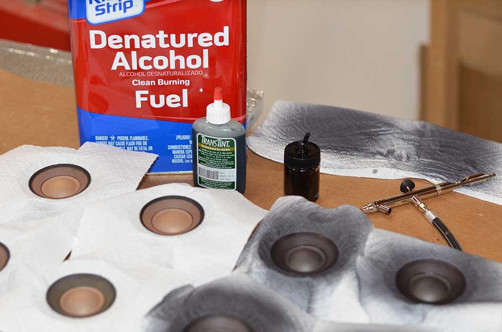
You may want to consider dyeing the mid-ranges if they will be exposed in the final design. The light grey color of the stock drivers gives me the impression of sun fade. Dye (as opposed to paint) adds negligible mass to the driver. I’ve used either alcohol or acetone to thin the dye and an air brush to apply multiple thin coats.

I’ve only used black dye, but I don’t see any reason that other dark colors wouldn’t work. Dyeing may also help match the color of the cone to that of the replacement dust cap.
Glitch
GlitchBRONZE MemberHave you made any progress on the midrange rebuild? Did you decide to remove the dustcaps as part of the rebuild?
I think the symmetric design is more aesthetically pleasing than the non-symmetric. Will the final design be ported?
You mentioned paying homage to the original Penta style. Have you considered angling the woofer modules outward? This would have the visual effect of slimming down the side profile of the cabinet. I have no idea of what the sonic impact would be. However, since the overall shape would now be hexagonal, you could call the speaker a CentaHexaPenta ;-).
Glitch
GlitchBRONZE MemberAwesome! Seeing that made my day!
Glitch
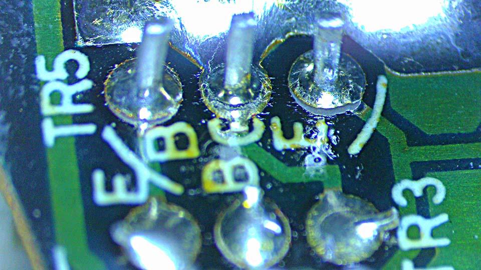
GlitchBRONZE MemberI didn’t find a specific reason for the overheating. The first step of this Beomaster repair was to remove the circuit boards and inspect them under a stereo microscope. I like to make repairs to any “mechanical issues” (i.e. cold/cracked solder joints, cracked boards, solder bridges, etc.) before applying power for the first time. I recall fixing what appeared to be shipping damage, but my notes are sketchy. Unfortunately, the quantity/quality of my note-taking can be inversely proportional to my excitement about working on something and I was pretty stoked about digging into the project. 😉
I did take a few pictures of the more interesting discoveries.

Power relay contacts
Broken solder pads on fan control board.

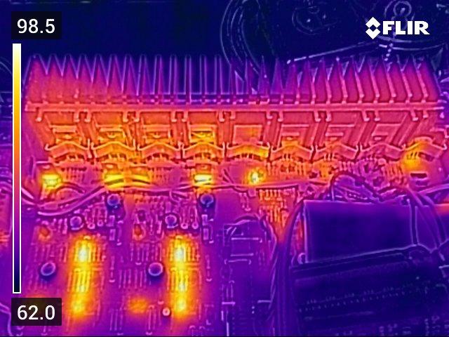
The Beomaster is running at “as expected” temperatures. Warm, but not hot enough for the cooling fan to engage.
Glitch
GlitchBRONZE MemberI spent some time researching and working out a way to send such a fragile piece, and I think I have found a good solution. I will custom make the boxes which should be able to withstand international shipping. The aim was to make a box that doesn’t compress or twist and which weighs less than 1kg in total to make shipping more affordable.
I like the box. Very neat. A minor improvement would be to add some support between the ends of the “U” (i.e. make it structurally more like an “O”). This would reduce the chance that the plinth breaks due to its own mass during a hard impact.
I’m always a bit surprised by how brutal shipping can be. When I pack something for shipping, I imagine it being dropped off a moving vehicle, then sat on by a toddler. 😉
Glitch
-
AuthorPosts