Forum Replies Created
-
AuthorPosts
-
 GlitchBRONZE Member
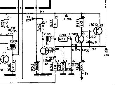
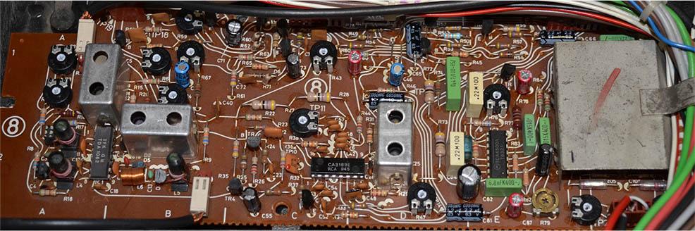
Here is the signal mute circuit. The signal coming in to R244 comes from the FM circuit. If I am interpreting this right, removing TR208 should disable the mute signal as a test.
Glitch
GlitchBRONZE MemberStill… B&O are trying to be hip, which is at least an effort. ?
Like Adidas/Gap were trying to be hip partnering with Ye? Sometimes things don’t turn out like were planned. I don’t think that this will go bad for B&O, but you never know.
Please don’t confuse these with ‘real case’ NFT’s which will come when we fully adopt Blockchain technology.
I think that NFT’s could be a very useful technology if applied properly. Using them to try to create wealth from something of questionable value probably isn’t the killer application. #tulipbulbs
Glitch
GlitchBRONZE MemberIf the 15v rail is failing, my question would be why? I’ve not often seen a failure on a power rail without some serious damage. And it would also stay broken, not degrade with time?
The voltage could drop due to the voltage regulator overheating (i.e. bad thermal connection to the heat sink), or the system drawing more current than the regulator can provide (i.e. some other device drawing too much current), or a combination of both (i.e. high current draw causing the regulator to overheat). The device wouldn’t have to completely fail. Think of it more as going into a self-protection mode.
Have you been monitoring the output of the Overload Circuit? Could it be something as simple as a bad light bulb in the circuit causing it to work improperly?
Glitch
GlitchBRONZE MemberMy interpretation is that most of the negative comments on this topic are based on people really caring about the company. When they see something heading in the wrong direction (from their point of view), they get upset.
I don’t know how NFT’s will play out over time. There have already been documented cases of NFT’s being outright fraud. Many believe that NFT’s are based on the Greater Fool Theory. I’m a bit less jaded and put them in the category of conspicuous consumption.
Regardless of the where NFT’s are heading, it is the effect that they could have on a company’s reputation that concerns me. These newly issued NFT’s are likely to be as legitimate as a NFT can be. However, if enough of the NFT’s issued by other sources go bad, then B&O will be guilty by association. In business, reputation is everything, and should be fostered and defended vigorously. It is surprising to me that B&O would take a risk like this.
Ultimately, I think that how this is viewed will depend on the issue price. If the prices are low, and the B&O NFT’s are viewed like fun little tchotchkes, then it is a cool marketing ploy. If they are offered at investment level pricing, then the reputation risk goes up.
Glitch
GlitchBRONZE MemberAren’t NFT’s the modern way of doing this? 😉

I’d rather have the bottle opener.
Glitch
GlitchBRONZE MemberIs the thermistor R40? If so, the service manual calls it out as “50 0hm 30% PTC”. You can test it by removing it from the circuit, hooking it to an ohm meter and observe the resistance as you heat it up with something like a hair dryer.
I would also make notes of all of the voltages from the power supply and see how they change with time and temperature. From the schematic, it appears that many of the voltages are referenced from the +15v supply. If this dropped down, many of the other signals would follow.
Glitch
GlitchBRONZE MemberMaybe you can work out some sort of “swap” with the seller to save money? (Might not work due to the cost of shipping)
GlitchBRONZE MemberHave you checked the thermal compound and mica insulators?
Sometimes, the thermal compound is fine after decades, other times it has dried out and shouldn’t be trusted.
Mica insulators can split between layers. These will look like there are air bubbles in the mica. Mica is a good thermal conductor, air is a good thermal insulator.
Disassembling, inspecting and replacing the thermal compound with modern, higher performance compound doesn’t take that much time. Even if it wasn’t needed, it can provide peace of mind.
Addition: The above comments are primarily targeted to the power supply components. These might affect both channels simultaneously. Also, if you have a FLIR camera, it is really useful for debugging potential thermal issues.
Glitch
GlitchBRONZE MemberIt might “work”, but you should be cautious. The outputs of the transformer will be “off” by the same percentage as the percentage difference of the input voltages. This likely won’t affect any regulated DC signals, but will affect unregulated AC signals. You would have to carefully study the schematic to understand the ramifications.
I would be more concerned about the liability associated with such a modification. If this modification caused a fire in your home, would your insurance cover the damage? What happens if the receiver is sold and the next owner has an issue? If you swap out the transformer for the proper one, you would have an easier time justifying the change.
Personally, I would look for someone parting out a similar machine. In general, there isn’t much demand for transformers since they typically don’t go bad. When people part out machines, the high failure rate items sell very fast (and at a premium). This leaves the seller with the low demand items that they will often sell cheap just to get rid of them.
YMMV,
Glitch
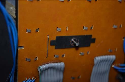
GlitchBRONZE MemberI thought the same thing when I first noticed the part. It seemed like an awkward design to me.
However, both of my BM8000’s have this part in that location. I bought one of the BM8000’s used, so I can’t make any judgements about the originality. The other I purchased new and the only placed that serviced it was an authorized B&O dealer. It is possible that two different people did the same hack independently, but the odds are slim. Maybe it was a something from a B&O Service Bulletin?
Here is a picture of the button board from the other BM8000

Glitch
29 October 2022 at 01:03 in reply to: Strategy for Changing Capacitors and Trim Pots on FM Tuner #39366GlitchBRONZE MemberI’ve been able to do a full adjustment of the FM tuner on a BM6000. I more or less gave up on trying to follow the exact directions in the service manual since it was not clear to me how to translate things like the signal levels, etc. to the equipment that I have. Instead, I used the service manual as a guide, along with the schematics, theoretical descriptions of FM tuner operation, and (better) explanations from service manuals for other (non-B&O) equipment to interpret the “spirit of the adjustment”.
To relate the signal levels to my equipment, I made measurements of the other four Beomasters that I have that (I think) still had their original adjustments. I took notes and used the trends from the sample set to setup the tuner that I replaced the caps and trim pots on. This was a bit challenging since all four tuners were setup somewhat differently.
My newly adjusted tuner now sounds as good as the best of the other tuners and quite a bit better than the worst of the other tuners. I have no idea if it is actually adjusted “to specification”. It sounds “good enough” that any misadjustment isn’t readily noticeable.
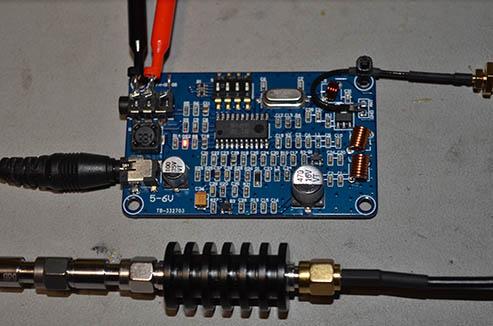
I was able to do most of the adjustments with a digital oscilloscope, a multimeter, a TinySA, and a handful of attenuators. I needed one other piece of equipment to set the Channel Separation. The service manual called for a stereo encoder. I used a cheap FM transmitter, a waveform generator and attenuators to get the signal down to a proper level.
I’m happy with the results. I’m happier that I didn’t have to spend more than the receiver is worth on equipment to fix the receiver.
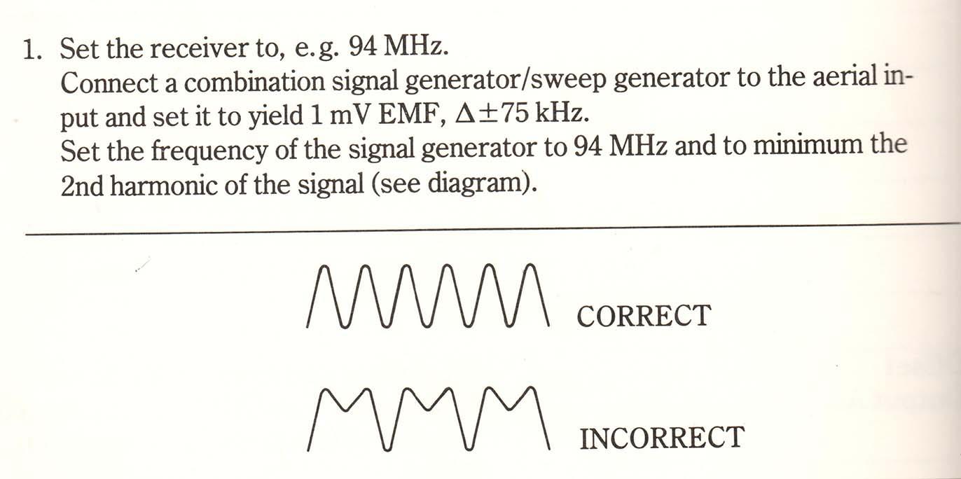
I still want to refine and improve my adjustment procedure. One of the things I still don’t understand is what they are trying to convey in this paragraph of the manual

What “signal” do they mean in the 2nd harmonic section and what is one supposed to adjust to get the correct waveform?
Glitch
GlitchBRONZE MemberI don’t see any screw holes and I don’t want to go randomly prying.
I assume that you didn’t have any luck finding a service manual.
If you do have to resort to “randomly prying”, having the proper tools can make a difference. Pry tools like they sell at iFixIt can help getting stubborn devices open with minimal damage. The plastic pry bars are softer than many of the plastic cases.
When it comes to opening cases, everything is fair game. I’ve used everything from credit cards, to guitar picks, to painter’s pallet knives to get into devices.
When I don’t have any clues on the proper way to get something apart, I start with the spot that will be least noticeable if the device is damaged by opening. Some manufacturers are kind enough to design the initial pry point in a discrete location to help out the people servicing the device. YMMV.
Glitch
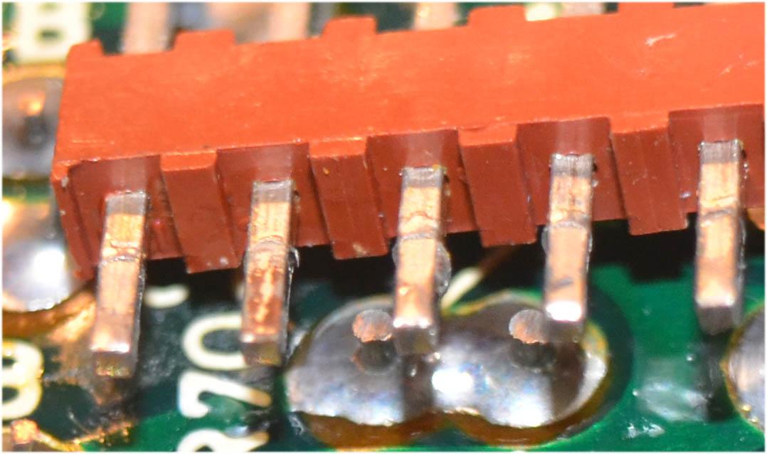
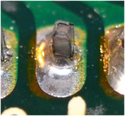
GlitchBRONZE MemberGlitchBRONZE MemberVery close inspection of the connector pins is recommended. The attached picture is of the board side of a connector. The solder holding the connector to the board was actually fine, but the plating came loose from the pins. You can see some corrosion on the raw metal of the pins (second pin from the left was worst). Just reflowing the solder on this connector probably would not have resulted in a long term fix.

Here is what the solder joint looked like…

Glitch
19 October 2022 at 17:12 in reply to: Strategy for Changing Capacitors and Trim Pots on FM Tuner #39365GlitchBRONZE MemberCraig: I’m pretty happy with the TinySA. It has already provided me sufficient amusement for how much I spent on it. It seems like most of the people using it are HAM radio enthusiasts. But there also seems to be many people trying to adapt it to other, more imaginative, uses. The author of the TinySA software seems to embrace the “alternative usage” and tries to accommodate with patches and Easter eggs. I’m still not 100% sure of the TinySA’s suitability for what I’m trying to use it for. I keep seeing the advice on various websites to buy the “proper equipment” for the job, but it is still not clear to me what the “proper equipment” actually is, or if it can be obtained for a price that I’m willing to pay.
I keep having the the thought that “this would be so much easier if I knew what I was doing” ;-). I’ve found there to be a simultaneous “information vacuum” and preponderance of information relative to this subject matter during my web searches. I’ve been struggling to find information relevant to the tuner design that my particular Beomasters have. I guess the best I can hope for is to plod-on with my experimenting and try to stumble upon a method that gives acceptable results.
On a more positive note, I did make progress on interpreting the “markers” that are on the sweep traces. It looks like the TinySA injects a marker at the ~320kHz and ~640kHz points during the sweep. I set my total sweep to 960kHz so the markers are even. I’m not sure why the TinySA uses these particular values or what the utility of the markers are, but at least it is clear when they are happening.

Glitch
GlitchBRONZE MemberThe best and most reliable option is to replace the connectors. However, you will likely be fine with just protecting the newly cleaned connector so it doesn’t re-oxidize quickly.
A light coating of Deoxit is most likely all you need. Any light oil would also work in a pinch.
Another option is to “tin” the connectors with a very light coating of solder. If the pins are brass, this is quite easy to do.
I would start with one of the above options, then if the issue returns, go though the trouble of replacing the connectors.
Glitch
16 October 2022 at 18:01 in reply to: Strategy for Changing Capacitors and Trim Pots on FM Tuner #39363GlitchBRONZE MemberI’ve made some progress with my quest to properly set-up FM tuner boards. I decided to experiment on the the tuner from my most beat up BM6000 (~5.5 of 1o condition). This receiver seems to be becoming my “parts machine” (or garage machine) as the best parts slowly migrate to my nicer machines. If I am successful with this experiment, I’ll use what I learn in the restoration of the nicer BM6000’s and BM8000’s.
I’ve worked through replacing all of the capacitors and most of the trim pots. I replaced only the trim pots related to a specific adjustment in the service manual at a time. I noted the settings of the old trim pots and checked/documented the “before” measurements of the circuit. For some of the measurements, I tried tweaking the old trim pots to learn the effects before replacing them. I skipped the steps that involved adjusting the inductors.

In general, I was able to make measurements and adjustments that “seem” like they are correct and consistent with what I’ve researched online. However, I don’t have the experience to know for sure if they are actually right.
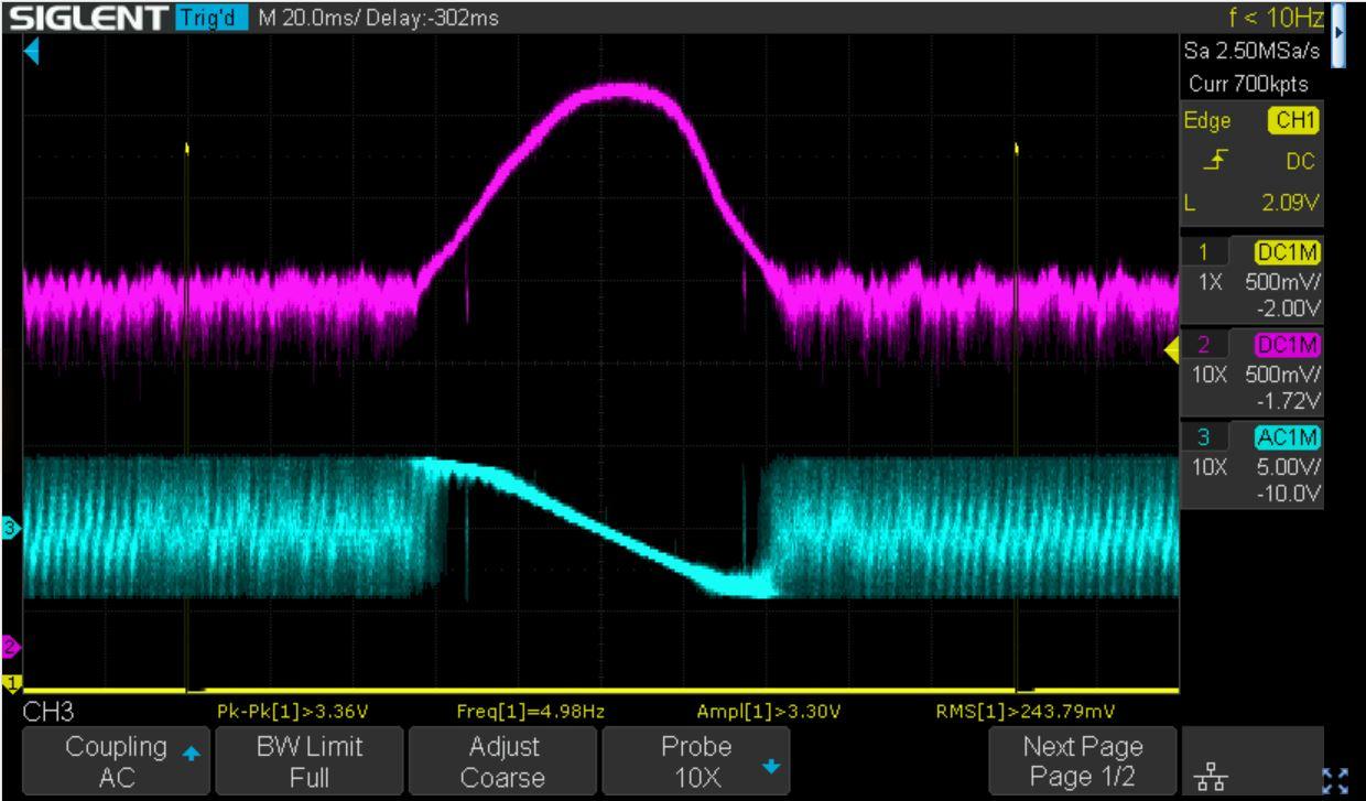
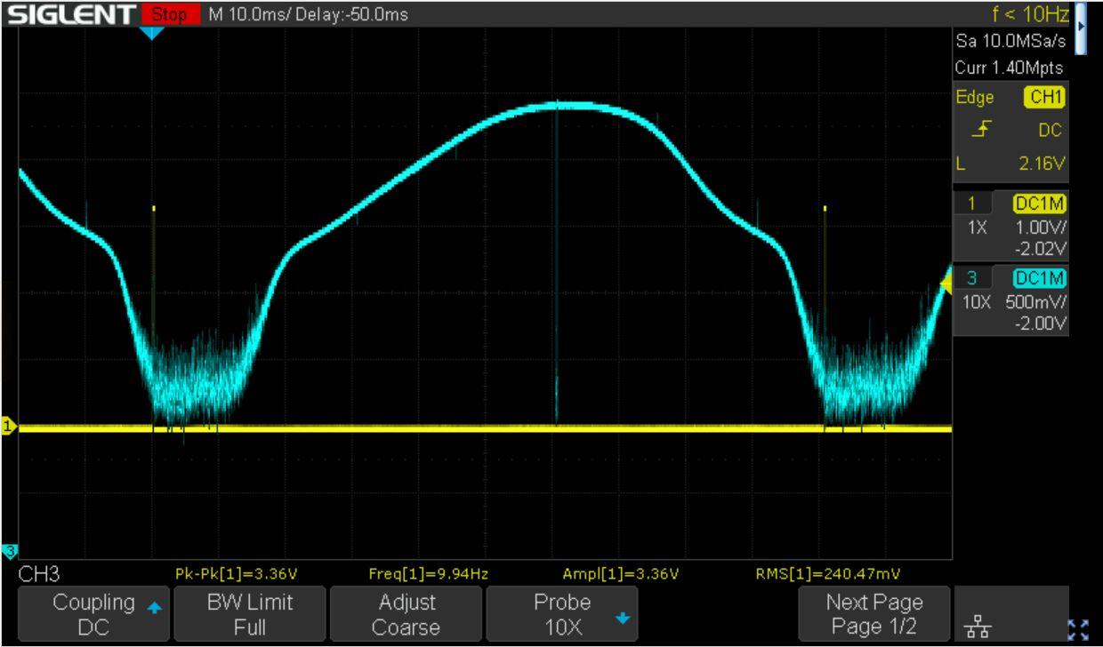
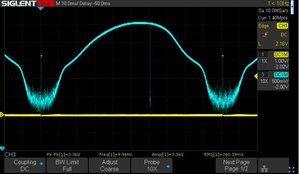
Tuner/IF Adjustment: Using the TinySA and an oscilloscope, this is what I got for a IF curve.
Here is the “before” capture with the OLD trim pots at the LOW end of the frequency band, 85.5 MHz. I don’t have an “after” capture for this since this measurement is adjusted only with inductors.

Here is the “before” capture with the OLD trim pots at the HIGH end of the frequency band, 108.0 MHz.

Here is the “after” capture with the NEW trim pots at the HIGH end of the frequency band, 108.0 MHz.

I was able to see the amplitude of the IF curve change as I moved each trim pot and adjusting to a point where it peaked seems to make sense. I wasn’t able to change the symmetry of the curve significantly. I did note that the “centering” of the IF curve was sensitive to the tuning knob position. I tried to position the knob half-way between where the display changed between 0.1 MHz below and 0.1 MHz above the intended frequency. I don’t know it was the right thing to do.
When I did these adjustments, I did not pay much attention to the “blip” near the center of the IF curve. I originally just thought it was an anomaly (random noise) in my setup. This may actually be a feature of the TinySA and be a “marker” at the center of the sweep. Unfortunately, the documentation for the TinySA is sparse and the firmware is still somewhat fluid, so some educated guessing is needed. I have some more research to do here.
If the “blip” is a center marker, would it make sense to center the marker with the tuner knob, then try to adjust for symmetry with the trim pots?
Another area that I have questions relates to an earlier question about the “mV EMF” level. I noted that some of the settings seems to be pretty robust to the input signal level. Other settings, like the “AGC” and “Opening of the Stereo Decoder” were sensitive to the input signal level. I think that the interpretation of the meaning of Vac is what is messing me up, or at least is adding to the error. There is a 3 dBm difference between Vrms and Vpeak, and 9 dBm between Vrms and Vp2p. Any comments on how this should be interpreted would be appreciated.
How I handled this was to note the signal level needed to get the correct voltage measurement with the old trim pot, then initially set the new trim pot to match. Afterward, I then played around with resetting the voltages based on a Vrms assumption of the signal level. I am not very confident that this is giving me a 100% correct setting.
In general, the FM tuner successfully receives stations and sounds similar to what it did before I installed the new parts and readjusted. Some aspects of the sound quality actually seem slightly improved. However, I still don’t think that it is exactly right. On some stations, on particular songs, there seems to be a slight fuzziness or distortion. I’ve also noticed this on one of my other tuners (that I haven’t touched). Any ideas on what I could be experiencing?
Glitch
As a side note, I tried experimenting with using the “3C” method from the original post. For some of the measurements, it provided a results that were pretty close to the final setting. The FM would “work” but could easily be improved with a proper adjustment.
Here is my 108 MHz IF curve with setting R1-R4 with the “3C” method.
I think that I actually just got lucky with this result. I tried to see if the procedure was repeatable and the second time was an epic fail.
11 October 2022 at 14:42 in reply to: Strategy for Changing Capacitors and Trim Pots on FM Tuner #39362GlitchBRONZE MemberGood idea to look at the chip spec sheet for clues.
I did some more reading and EMF likely refers to electromotive force. I think that last time I heard that term used was a very, very long time ago in college. It isn’t clear to me why it is being stated in that way. My best guess is that they are trying to indicate making a measurement on a signal generator with a low impedance built-in load with a high impedance measuring device (i.e. without a 50 ohm load at the scope)?
The spec sheets may have provided a clue to another question that I had. Which aerial input to connect the signal generator, the 300 ohm or 75 ohm? Seems like the 75 ohm is the proper one(?).
I’ve been playing with the TinySA to get a feel for how it performs. So far, the settings on the TinySA match what I measure on my scope. I still need to work out ways of measuring what I need with the equipment that I have. For example, I don’t have anything that can measure a 10 uV signal in the MHz frequency range. I think the many of the measurements that I need to make will have to be done indirectly.
Glitch
10 October 2022 at 17:18 in reply to: Strategy for Changing Capacitors and Trim Pots on FM Tuner #39360GlitchBRONZE MemberThe TinySA seems to be a pretty capable device, especially considering the price. It has its quirks and limitations, but I’m hoping that I can work around them.
I am having trouble understanding exactly what setup is be specified in the service manual. My (possibly incorrect) interpretation is that they are calling for a settings on a specific piece of unnamed equipment. I think I understand what they are trying to accomplish, but might be getting hung up on the nomenclature. For example, in the service manual…

The 94 MHz and 1 mV part is clear. Is the voltage amplitude, peak-to-peak or RMS? Does “EMF +-75kHz” refer to a injecting a wide band FM modulation onto the signal or is it just a tolerance? The term EMF is confusing since it means electromagnetic field to me. But that interpretation would have different units.
I’ve been searching the web for information on setting up FM tuners, but most of what I’ve found doesn’t seem to be applicable. Please let me know on any good resources that you are aware of.
It is clear to me that I have a lot to learn and that the learning curve is steep.
Glitch
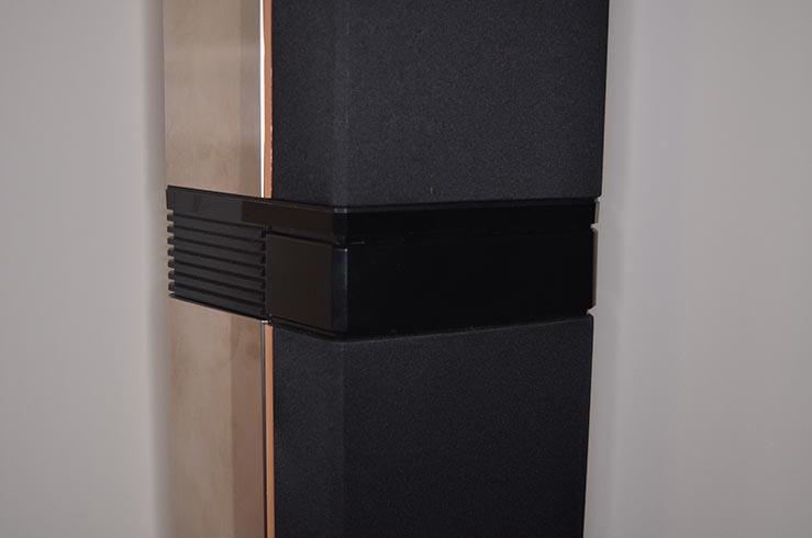
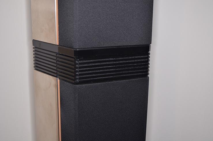
GlitchBRONZE MemberI decided to take the “restomod” path with my Pentas since they were a bit rough when I bought them used. The yellow covers were cracked and glued back together several times and looked pretty bad. The grill fabric was also in need of replacement. The bases had their share of scuffs and scratches. I ended up repainting all of the gray and mirrored parts. I went through two iterations with the display covers.
The first iteration was fill in the cracks and paint the covers. Of course, I lost the use of the displays. This is a feature that I really didn’t “need” and I haven’t missed having it.

The second iteration was to make a 3D printed part that matched the grooved trim piece. This actually matches much better than the picture makes it look (flash problem?).
I also experimented with designs with a painted cover with a cutout for the original display. I also tried fitting a replacement color TFT display in place of the original display. In the end, we (by “we”, I mean my wife) decided that the speakers fit our decor better without the displays.
Glitch
-
AuthorPosts