Forum Replies Created
-
AuthorPosts
-
Dillen
ModeratorSchottky diodes would make no difference to speak of.
And they have no place in power supply rectifying anyways, that’s not what they are meant for – or good for.Check the filter capacitors – also any smaller ones sitting in the analogue circuits.
Martin
Dillen
ModeratorAre your speakers MK2?
If so, the glasses seem to be very dark – perhaps they are in fact mkIII glasses.
See here:
https://www.dksoundparts.com/?s=penta+display+covers&post_type=productMartin.
30 August 2025 at 07:36 in reply to: Beolab penta 6621 “soft clipping” activates at moderate volume #69211Dillen
ModeratorCould suggest that the amp runs not symetrical.
Any DC on the speaker output?Martin
Dillen
ModeratorThe other fuse lives at the back right side, on the board way down in the corner.
Martin
30 August 2025 at 07:31 in reply to: SOLVED !! Beomaster 7000 has suddenly become very silent #69208Dillen
ModeratorIs the 8V present for the tonecontrol circuits?
If not, check 3TR4 (BC547B) and all filter capacitors related to the supply voltages in the preamplifier.Martin
Dillen
ModeratorWrongly set tracking force?
Bad stylus tip?
Defective lamp or LDR for the tracking system?Martin
Dillen
Moderator
Basically the same drive as yours.
Note the remark about the nylon washer.Martin
Dillen
ModeratorSolder the old one out and solder a new one in.
Then do NVRAM reset as mentioned in the service manual.Martin
Dillen
ModeratorDillen
ModeratorThe service manual shows how to adjust the black excentric.
Martin
Dillen
ModeratorFirst thing would be to replace the backup battery and reset the settings.
Martin
Dillen
ModeratorI am not as active here as I have been, I must admit.
Down from about a dozen posts a day to a few per month.
Discussions are now spread all over the net, which is a shame, I think.I am not on Facebook. Never was and probably never will be.
I never visited Discord.
Every B&O enthusiast has his own forum now, it seems. Or Facebook page or Instagram or …or…or…
Having to visit hundreds of places to get information or help is frustrating and it is wasting time looking
everywhere instead of one place – and keeping track of where what happens, where did I ask the question etc. – oh no, it’s not for me.
Better to concentrate than to water out in my opinion.We don’t have many dicussions about products within my scope of interest here.
I don’t care for TVs, I don’t care for video products more or less as a whole. I don’t care for home automation
and I have very little interest in apps.
I know next to nothing about the newer products, and I don’t service them.
I don’t feel the need to make things complicated – just for the sake of doing that – when it can be done simple.
I actually wrote a longer piece about this a while ago, but decided not to post it, as it was more or less just my own
reflections and not really particularly helpful.Martin
Dillen
ModeratorCheck the idle current settings.
Check for DC on speaker outputs.Martin
Dillen
ModeratorDillen
ModeratorSome versions have a fuse on the display board. Have you checked?
Martin
Dillen
ModeratorYou would need an FM-module,
either FM 5A:
or FM 6:
Both are immensely rare.
Martin
Dillen
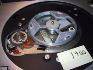
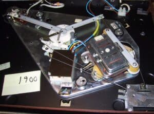
ModeratorSpeed switching is done by lifting/lowering the idler wheel, running it on different diameters of the motor pulley.
The lidting is done by rotating a wire so that the “pin” carrying the wheel moves up and down inside a “tube”.
The mechanism could have seized up – take apart, clean and lubricate.Martin
Dillen
ModeratorThese amplifiers blow with an “avalanche”, causing several components to burn and/or short.
It can be very tricky to find all bad components in one go – and if you miss one, it will start all over.
Seeing your board, I suggest you ask around for a complete amp module instead.
Perhaps not as challenging, but easily both faster and cheaper.Martin
Dillen
ModeratorBeomaster 8000 has a huge rush-in current when powering up.
Your lamp will eat most of the voltage the Beomaster needs to start up properly, and the surge will trigger the standby for safety.
Use a variac instead.Martin
Dillen
ModeratorPull the spring-loaded part only.
Not the whole round center assy.Martin
-
AuthorPosts

