


Home › Forums › Product Discussion & Questions › BeoCenter › Beocenter 9300 No Life – almost
- This topic has 18 replies, 5 voices, and was last updated 2 years, 2 months ago by

-
AuthorPosts
-
10 April 2024 at 09:41 #54194
 BRONZE Member
I just picked up a BC9300 for 15 GBP, advertised as defect but with a relay clicking.
True enough – I just connected it to mains, and I hear a click from a relay. Other than that, there is no stand-by light. I have opened the unit (the glass panel was of course loose, so I took that off), and I see no obvious signs. Is there a known problem, like e.g. cracked solder joints around a certain capacitor that I should look for, or should I start by seeing if I have the correct voltages as per the service manual?
Location: Copenhagen
11 April 2024 at 00:52 #54195auricBRONZE MemberCheck the fuses behind the cover where power cord goes into the unit.
But always inquire why the fuses blew in the first place!
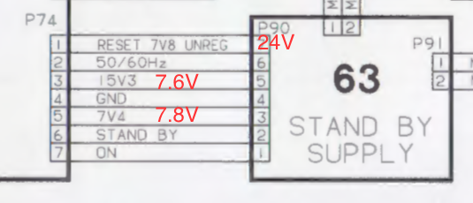
11 April 2024 at 10:10 #54196I have the correct voltages from the transformer. On the standby board I also have correct voltages except for P90 pin 1. It’s supposed to be 7.8V as I read the schematic (it says ‘7V8 unregulated’) but I measure approx. 24V.
Location: Copenhagen
11 April 2024 at 15:49 #54197Is the relay on the standby board supposed to click? Because mine doesn’t say a click.
Location: Copenhagen
11 April 2024 at 16:14 #54198.
Location: Copenhagen
11 April 2024 at 17:35 #54199All fuses were good.
Location: Copenhagen
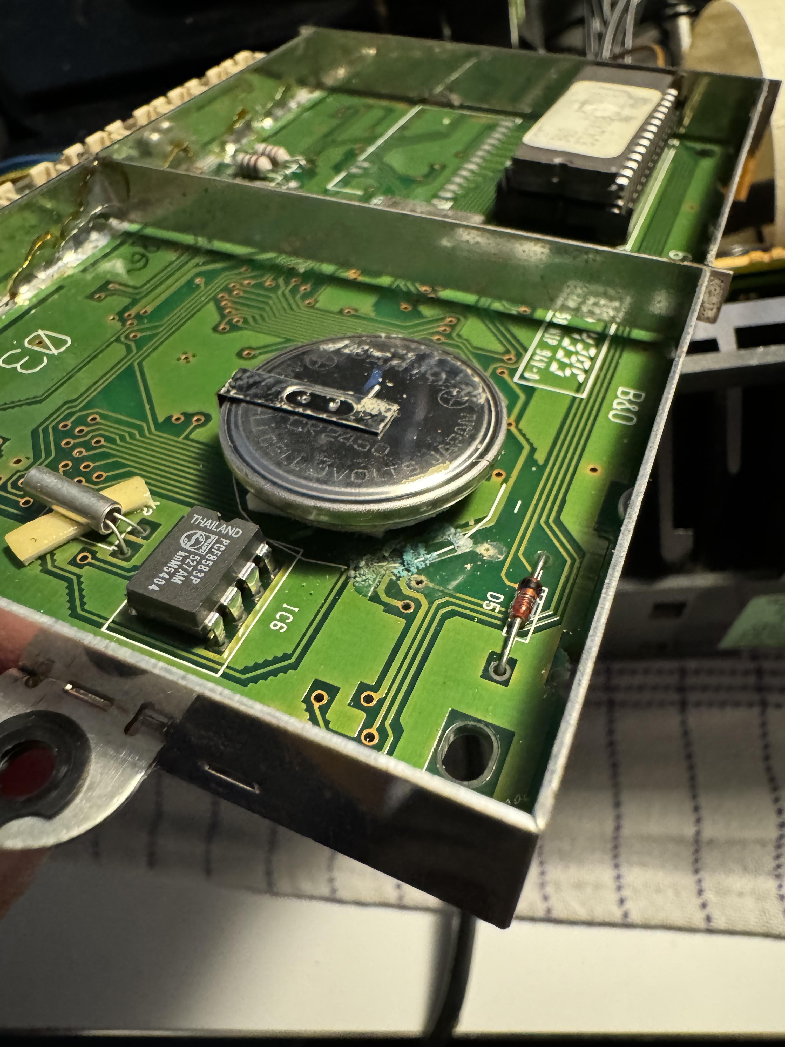
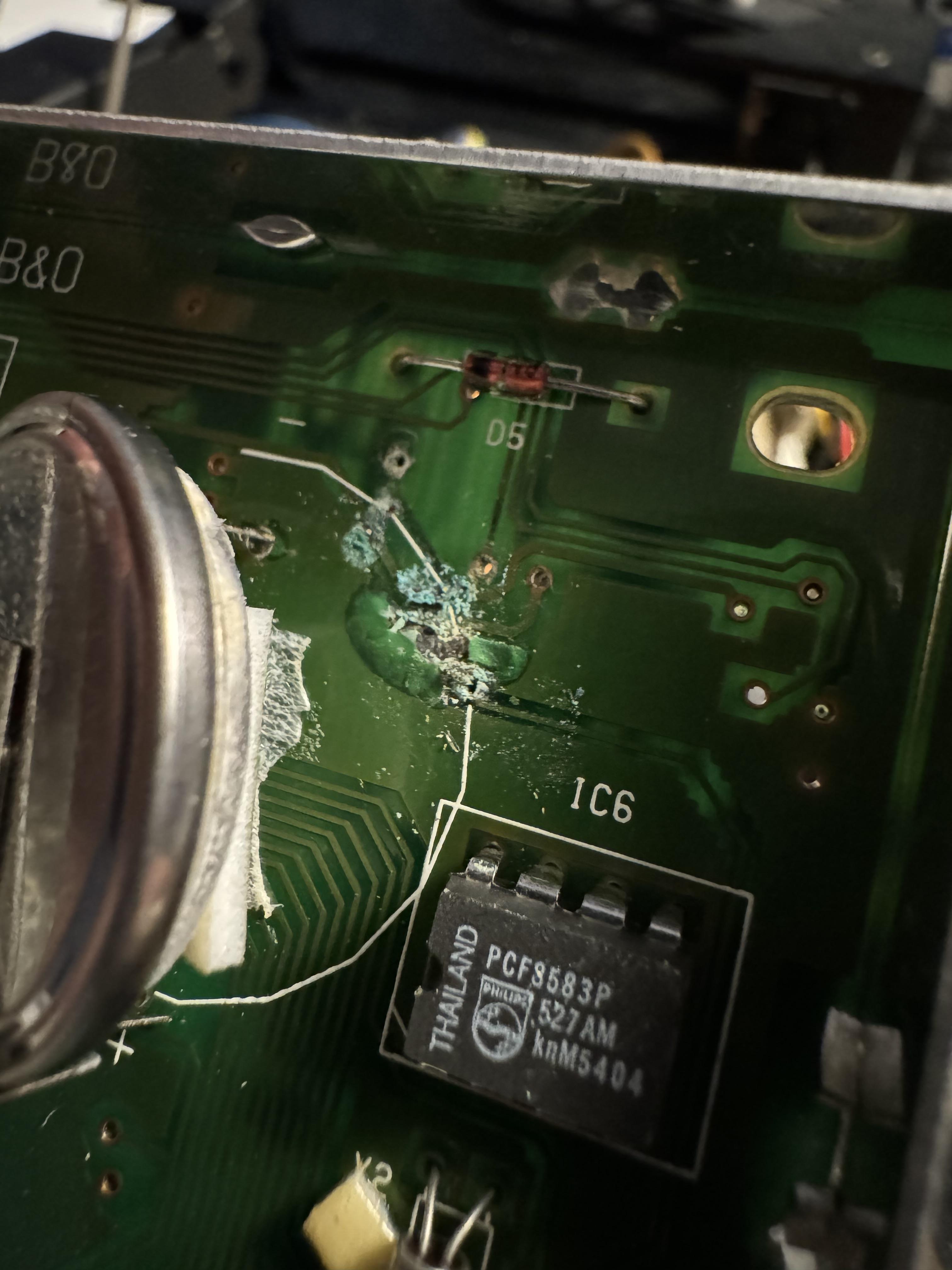
11 April 2024 at 21:49 #54200I guess I should have started by checking the battery:

There was only one trace that was broken, so I fixed that. Those batteries are a ticking time bomb ?
Location: Copenhagen
12 April 2024 at 07:28 #54201MadskpGOLD MemberYeah those batteries can make a mess.
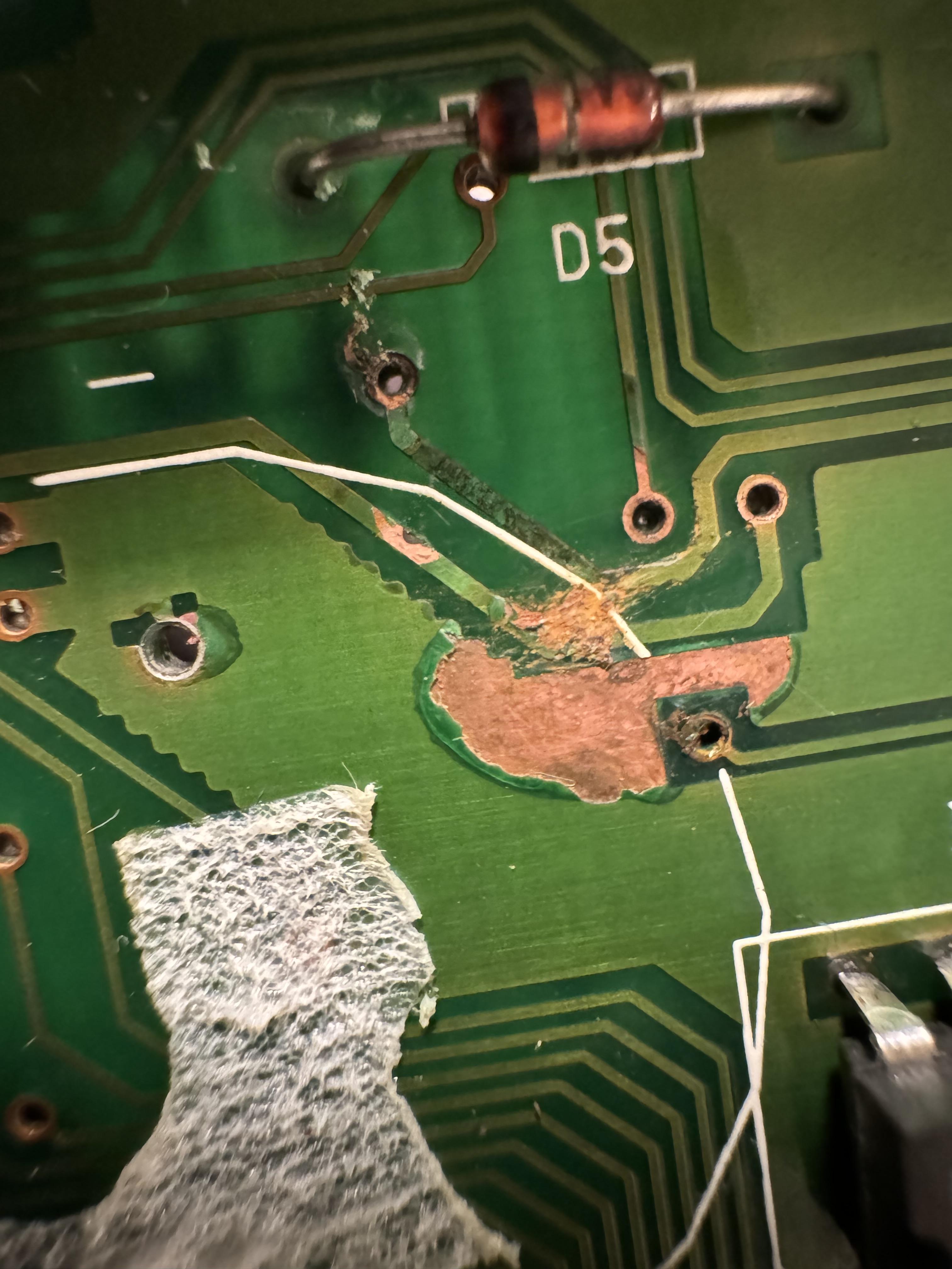
I don’t know if it is just the picture, but it looks like there is a crack in the diode D5
Location: Denmark
12 April 2024 at 08:28 #54202I have just replaced the battery in the electronically similar BC2300 – see thread here:
https://forum.beoworld.org/forums/topic/beosound-ouverture-cd-not-working/page/2/#post-29315
But after seeing your picture I may speed up battery replacement in my other similar aged B&O devices.
Location: Warwickshire, UK
My B&O Icons:
 12 April 2024 at 09:33 #54203
Yeah those batteries can make a mess. I don’t know if it is just the picture, but it looks like there is a crack in the diode D5
Indeed, it does look that in the pictures. I have just re-opened it and tested D5, and there is no crack, and it measures fine. But thank you – because I originally forgot to test that diode. Now, off to my favourite all too expensive diode pusher.
Location: Copenhagen
12 April 2024 at 12:58 #54204After changing the three diodes on the standby board plus fixing the trace on the processor board, the tape motor now spins but that is all. I still don’t know why I have 24V on pin 7 when it should be 7.8V. My measurements in red below. I am also missing a 15V supply.

Location: Copenhagen
12 April 2024 at 13:18 #54205When the motor is spinning, pin 3 gives 15V – but it is not every time the plug is plugged in that the motor will start.
Location: Copenhagen
12 April 2024 at 19:13 #54206I think there’s still an issue with the micro processor board. I realise I made a mistake repairing the dead track but now that it’s fixed to the right points, there is no relay clicking. I did experience that some of the panels lit up but I don’t know what I touched prior to that. Argh.
Location: Copenhagen
12 April 2024 at 22:02 #54207Can someone please upload a clear, zoomed in picture of the cpu board front and back? The service manual scan is not very clear.
Location: Copenhagen
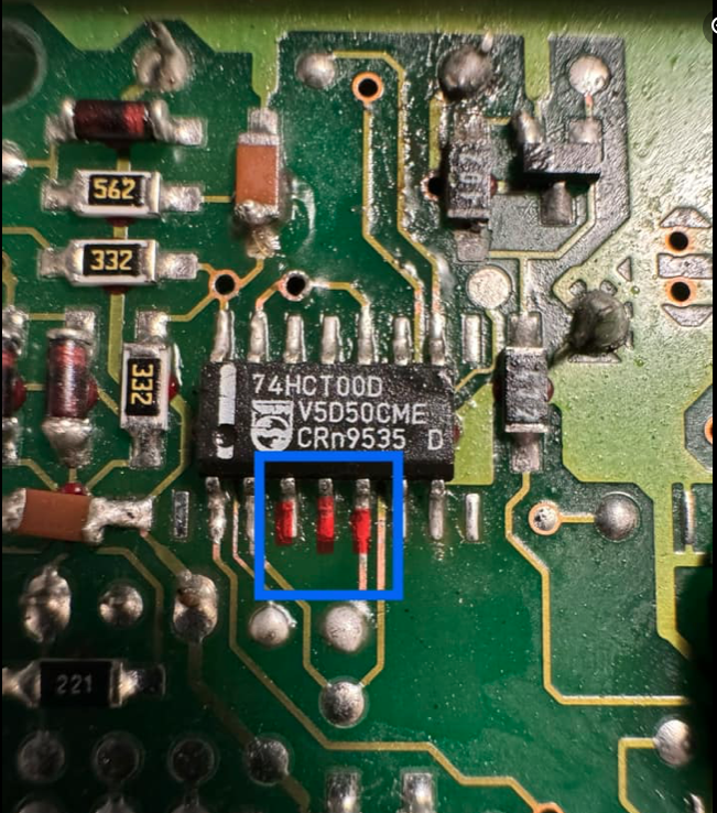
14 April 2024 at 21:45 #54208Hmm – these three legs are shorted. Am I right in assuming that they shouldn’t be? It’s pcb3. When the board is not connected, the BeoCenter starts up with two relays and the tape motor kicks in. The chip is right under the battery damage on the other side, so who knows what’s underneath of great surprises.

Location: Copenhagen
15 April 2024 at 22:40 #54209Turns out the three pins get the same signal but there was a broken trace under the IC.
Location: Copenhagen
16 April 2024 at 13:46 #54210The 7400 is a quad NAND gate. Connecting three pins together isn’t uncommon. You do it when you use one gate as an inverter.
16 April 2024 at 20:47 #54211Yes – thank you.
I have now turned my attention to board 10. Since I am getting 24V on P74-1 (and it should be much less – 7.8V unregulated), I am looking at TR36, and it is not working properly, so I will have to replace that.
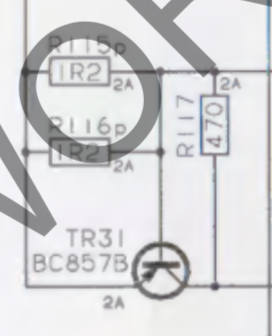
However, it puzzles me that there is seemingly a short on the board. TR31 measured a short, so I took it off but even without the component, I still measure a short 🙁

Location: Copenhagen
9 May 2024 at 18:20 #55422I changed Tr31 and Tr36 but the unit is still dead. A relay clicks and the tape motor runs but that’s it.
Location: Copenhagen
-
AuthorPosts


- You must be logged in to reply to this topic.