Forum Replies Created
-
AuthorPosts
-
 StanfordBeogramBRONZE Member
This is fantastic – and very well laid out. Would it be possible to design one to work with an independent IR sensor so that it may be solely used as with a Beolink remote?
Please let me know how I may purchase on of these beautiful boards!
StanfordBeogramBRONZE MemberHi Mark,
I was able to find another BC143 transistor! I installed it and the Beogram works, but the “<” button does not work. For some reason, I cannot seem to find what part of the circuit is responsible for the “<” button. Any ideas?
Thanks again!
Ian
StanfordBeogramBRONZE MemberHi Craig, Martin, and chartz.
Craig – the fuse did separate completely. I will order a couple of new ones along with a replacement of all the components (aside from the reed switches) of the voltage regulator circuit – might as well have the peace of mind for a few bucks and some time.
Martin – I was measuring the inputs on the fuses – in AC mode. The ground was chassis ground.
Question – if inrush current is problematic on these old Beogram transformers, could one simply install an appropriate thermistor to limit inrush current (and what would the ohms, amperage, etc would the thermistor need to be)? Or would a separate inrush limiter circuit need to be in place? I would love to solve this issue with the installation of a thermistor or new circuit. I found an example – see photo below.
chartz – The Beohub board is one that I designed for (a relatively easy) replacement of the filter power supply capacitors that simply installs in the old section with the chassis screws. I have created one for the 4000, 4002 AC, and 4002/4 models. I may make adjustments on the AC motor models (4000, 4002) given advice and guidance from Martin or others. Here are the boards:
StanfordBeogramBRONZE MemberHi Mark,
I am currently in the process of replacing all associated components in both the servo motor control and solenoid circuits. Upon inspecting TR-22, (the BC143 transistor)I found that it does not test properly and I compared it with the one on my other 4004 board that functions properly. I suspect that this transistor has failed and I ordered a NOS replacement from Littlediode in the UK. It should arrive in the next few weeks. I will report back the findings and hopefully this solves the issues with this board. Thanks!
Ian
StanfordBeogramBRONZE MemberHi Craig,
Thank you for your post! I wasn’t even aware that there was another fuse in that section. Upon inspection, it is obvious something got very hot – either the fuse or another component, my (safe) guess being the fuse.
The yellow sleeve for the fuse is burnt and the associated PCB also looks burnt – after replacing the fuse, should I replace the other components near the dark area?
I will check the output of the bridge rectifier 2D5, once I get a new fuse and hear from you. Speaking of which – do you know what the voltage and amperage the fuse should be?
Ian
StanfordBeogramBRONZE MemberHi Martin,
The white wires are being used as jumpers. The previous owner had no electronics and soldering experience. When replacing capacitors, he ripped up PCB wire hole tracks ?.
The board with the Bang & Olufsen logo is a replacement 4000 uF power board, to replace the original obsolete unit. It’s just for my personal use and I was playing around with PCB silkscreening.
Ian
StanfordBeogramBRONZE MemberI took your advice and started checking all the voltages and connections – once confirming that all of the white jumpers were correctly wired, I then decided to test all of the black transistors. TR-6, TR-17, and TR-19 (which given the schematic, seemed to cause the servo motor issue) were each out of spec and were replaced with new BC 547B transistors.
Now the issue of the 33 RPM button engaging the slide transport, is gone. I can press the 33 RPM button and the unit will not engage the slide transport without me pressing “<“. That said, when pressing the “<“ after pressing the 33 RPM button, the slide transport starts, but then dies. Some progress, although minute!
The “START button will only work by pressing and holding it down. The slide transport (now) seems to be the correct speed and not fast as before. Once “START” is let go, the slide transport stops and the solenoid engages and disengages. Allowing the slide transport to go clear to the end results in it wanting to return, but with the issue of the slide transport stopping and the solenoid engaging and disengaging (all while holding “START”). I have uploaded a new video here of an explanation and the phenomena.
StanfordBeogramBRONZE MemberHi Mark,
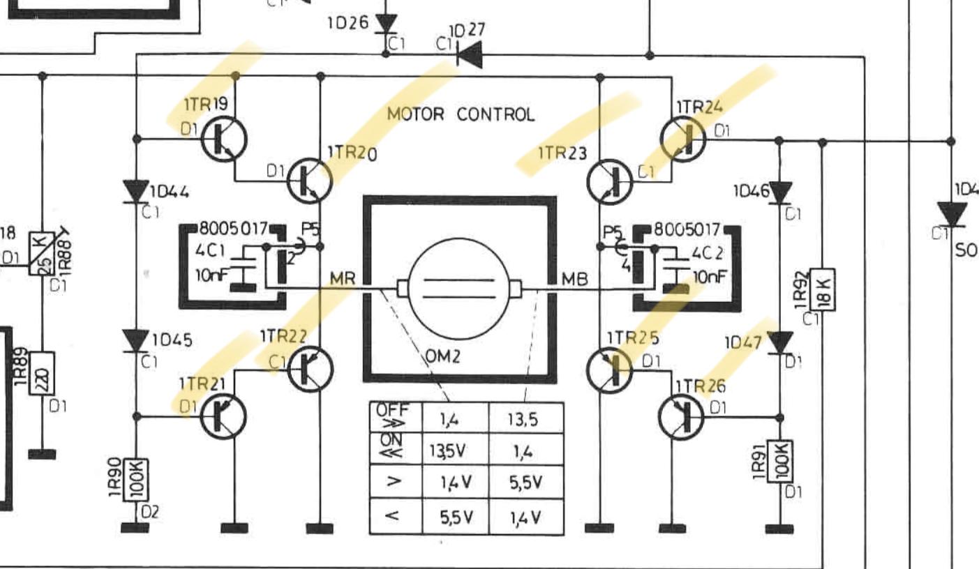
Is this the relevant section of the schematic with all the associated transistors?
 StanfordBeogramBRONZE Member
Hi Christian,
The red wire is at the front of the Beogram, as you indicated it should be.
The PCB with the 4 SMDs is one of the replacement power boards that I have developed.
Ian
StanfordBeogramBRONZE MemberHi Christian,
The red wire is at the front of the turn table, as you indicated it should be.
The PCB with the 4 SMDs is one of the replacement power boards that I have developed.
Ian
StanfordBeogramBRONZE MemberHi Mark-sf,
Yes, the turn table is able to move the arm inward with the “<” key and does stay, without turning off.
StanfordBeogramBRONZE MemberHi Mark,
Update: TR-19, and IC2 were flipped. I reoriented them and now everything is working, except for “START”. I replaced TR8 on the muting board and applied fresh solder to D9/D10 on the muting board as well – any other ideas?
StanfordBeogramBRONZE MemberThank you both for the replies!
I checked the fuses (both are good and were recently replaced). The voltage at the fuses was 123.5V AC.
I then checked the DC voltage at P3 – 1 and 2. The voltage was 33.9 VDC
I could not get a AC voltage reading at P3 – 3 and 4. I am guessing that this is and issue with my multimeter.
I proceeded to replace transistors TR12, 13, and 19. TR13 appears to be the transistor responsible for the “STOP” function and Tr12 the “START” function.
Now what happens is the same as before – the Beogram starts with the press of “33” and runs through until the return is activated. This time the return of the carriage is very very slow (as shown briefly in the end of the YouTube video found below). In addition, pressing the “>>” button starts the carriage going in the opposite direction. I am also unable to toggle between “33” and “45” rpm after having pressed “45”…
My knowledge of reading schematics is limited, so I really appreciate all the help and patience!
-
AuthorPosts