Forum Replies Created
-
AuthorPosts
-
 BRONZE Member
I would set the tracking force to zero, remove the arm cover and ensure the arm floats with no friction up to down. If it doesn’t you have found your issue and need to find where it is binding. Sometimes its the cover, tonearm wires too tight, sticky bearing, etc.
Emma, you’re welcome. Enjoy with your new addition!
I would check that if you manually lower the arm before the edge of the record that it goes down to just above the top plate. I would also check the tracking force calibration.
Most of the time with these models it is an issue with the ribbon cables between the main board and the other ones including the keypad. I would carefully reflow all of the connections on each cable end. I would also check if your 2MHz clock is running on Pin 11 of IC1.
In the first instance I have bought a new DIN to RCA cable from Sounds Heavenly as it does seem that B&O pins are wired differently – fingers crossed this works… will keep you posted!
Thanks so much again, Emma
Emma, if you get sound but have a hum using the Sounds Heavenly cable, return it and get one that has a separate ground wire that you connect to the thumb screw on your phono preamp. I included an example in my previous reply.
You need a Phono DIN adapter cable to go into your preamp such as this one: https://www.av-connection.com/?PNo=AV-DINPHONO&gad_source=1. The one you’re using is likely connected to the wrong pins and also needs the ground wire.
On a turntable that old, if its motor is not turning then the grease has hardened and bearings dried out. You never posted what is actually not working.
That is simply a chassis ground.
I’m not sure which wire you believe is totally missing. If you are referring to the Red/Black twisted pair in the first picture that appears unconnected, that is normal for 1000’s not equipped with a phono PC board. Yours simply has the jumper board that directly connects the tonearm cable to the output cables which then go into a preamp’s phono inputs. What is actually not working?
That capacitor is not your problem. You say you don’t have voltage at the 01C1 5V regulator. Does this mean that you measure 0V at both its input and output? If that is the case can you check the continuity of the F1 fuse? If it is good that means you have no output out of the diode bridge and its supporting capacitors. That’s where I would focus.
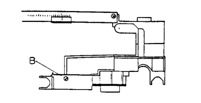
You need to adjust the aperture (B) so that the arm moves every 2 revolutions. Make sure that stray light does not leak in when doing it.

Your problem is not simply the knob. That amount of damage would have destroyed the arm bearing so that even if you could get the knob in the arm would damage records.
Thanks for the pictures. I’m afraid that level of tonearm bearing damage is not repairable.. You will need to replace the tonearm to restore the turntable. Many of these have bad motors so you may find one for parts that you can use its tonearm.
Dieter, I’m not following your description. Assuming you have a 1200, the rear counterweight when screwed fully in is factory to the tracking force as there was no user adjustment on that model. Perhaps you can post a picture.
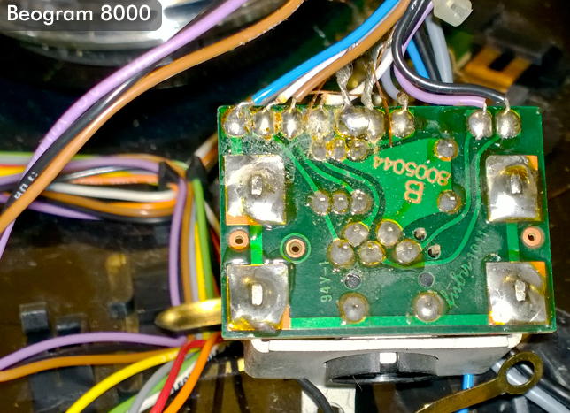
Looks like someone did a nice hack job. Here is a link to a picture with all the wires on the correct pads: https://archivedforum2.beoworld.org/cfs-filesystemfile.ashx/__key/CommunityServer.Components.PostAttachments/00.00.12.47.75/bg8000_5F00_din_5F00_pcb_5F00_01.jpg
You need to connect the black lead to a chassis ground which is available many places. For example, the negative terminal of C24 or C27.
First I would double check that All of the replaced capacitors are in the correct polarity. After plugging in, you should see a red dot in the display. If you are not getting that I would check that you have 5VDC at pin P6-1 which is powering the CPU, then work backwards to the Zener and regulator.
It appears that the arm is being blocked from moving inward once it lowers. I would check with it open and lowering the arm to the right of the platter. It should move freely the 1/2 inch to the sensor arm. Sometimes the optical shutter is sticking or has be rotated so it hits its stop prematurely.
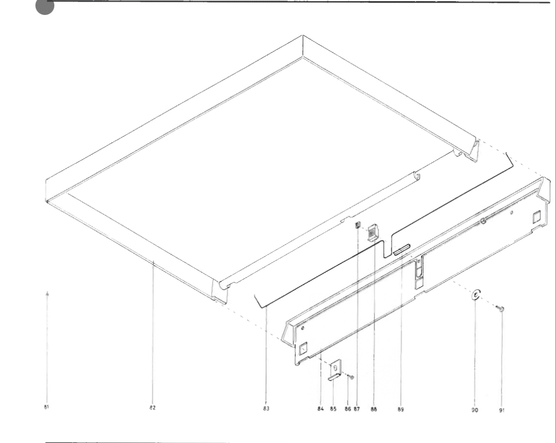
The Beogram 1500 was one of the first tables and had a lift off dust cover. That looks like the rear hinge assemble to a 1900. This is how they go together.
As Dillen replied 0TRi is mounted on a metal block heat sink screwed to the bottom and connected to the board on the solder-side. You can easily measure the voltage across it while pressing the start button to see whether it is passing 22V which is shorthand for “22 volts”. This is my last message to you on this as your combative responses and insistence that you did nothing to cause this non-operation are preventing a successful diagnosis and my help.
-
AuthorPosts