Forum Replies Created
-
AuthorPosts
-
OK – I fixed the issue 🙂
Upon disengaging the drive reel brakes, and disengaging the drive cog, I found both drive reels were stiff to turn manually. So for each drive reel: I removed the top circlip (which is microscopic, be very careful here!) then removed the drive reel components. I cleaned the drive reel shafts, and the drive reel bores with IPA. They all had evidence of dried lubricant / grease. I re-lubricated the shafts / bores and reassembled everything. The most difficult part is reinstating the circlips, which requires a very steady hand, and steadfast concentration. Upon reassembly, it was immediately evident that both reels were easy to turn manually. I powered the Beocenter up, and it’s now working fine! Play in both directions, FF & rewind are all operating as they should. I did notice the left drive reel was skipping a little when winding. This was more audibly obvious than visual. This was rectified by bending the drive cog metal stop away from the drive reel. I made three tiny adjustments followed by testing, until it was winding quietly with no skipping.
All sorted 🙂
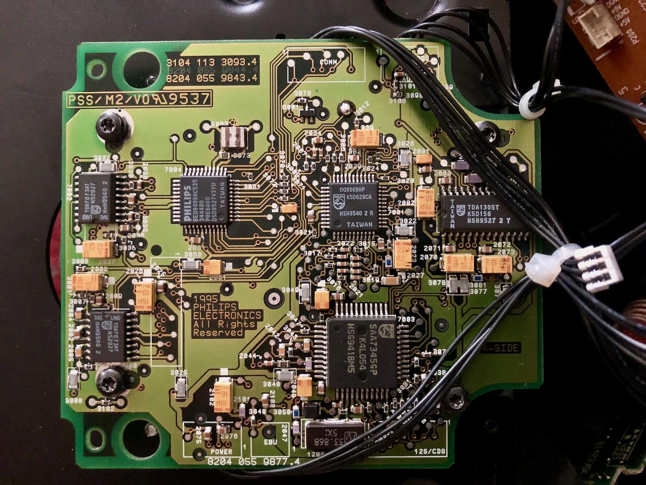
Well, that didn’t work! On replacing the pickup, and attempting to play a CD, the spindle motor did spin up this time, but my hopes were short lived. After a second or two, the spindle motor stopped, and the CD clamp opened. Placed the unit into Test Mode. It initially gave an error 7 on pressing CD, but now repeatedly gives an error 3. I removed & checked all the connections, but error 3 it is.
Thanks Guy
I continuity checked those joints, whilst flexing the ribbon, they were all good.
I may well replace the servo capacitors, and I’ve got a surplus of capacitors for the IR board, so they’ll certainly be replaced!
I’ve got a replacement pickup on the way.
Thanks!
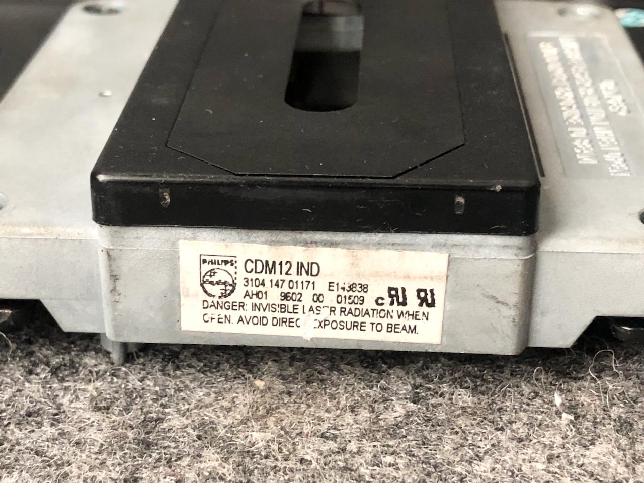
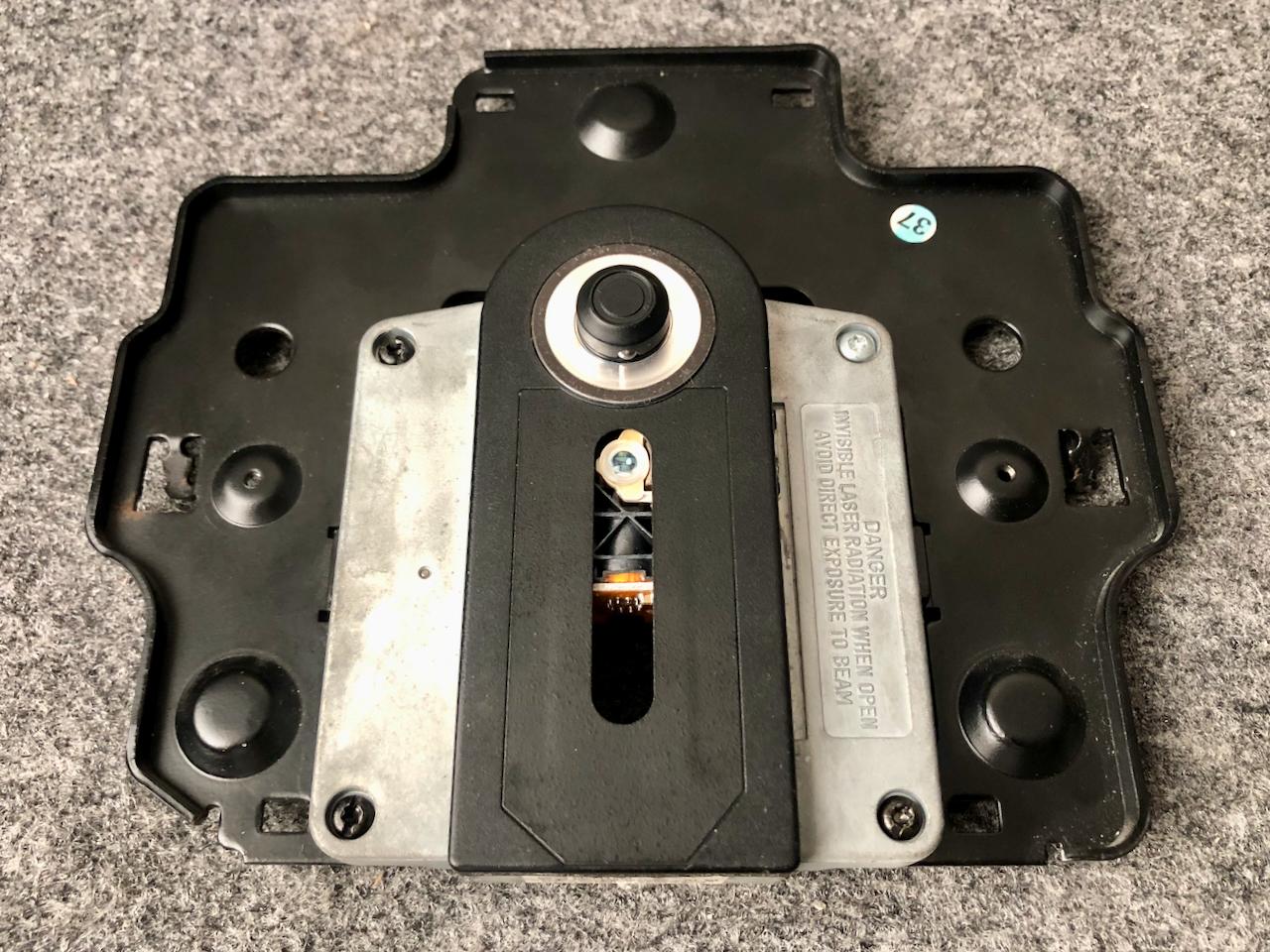
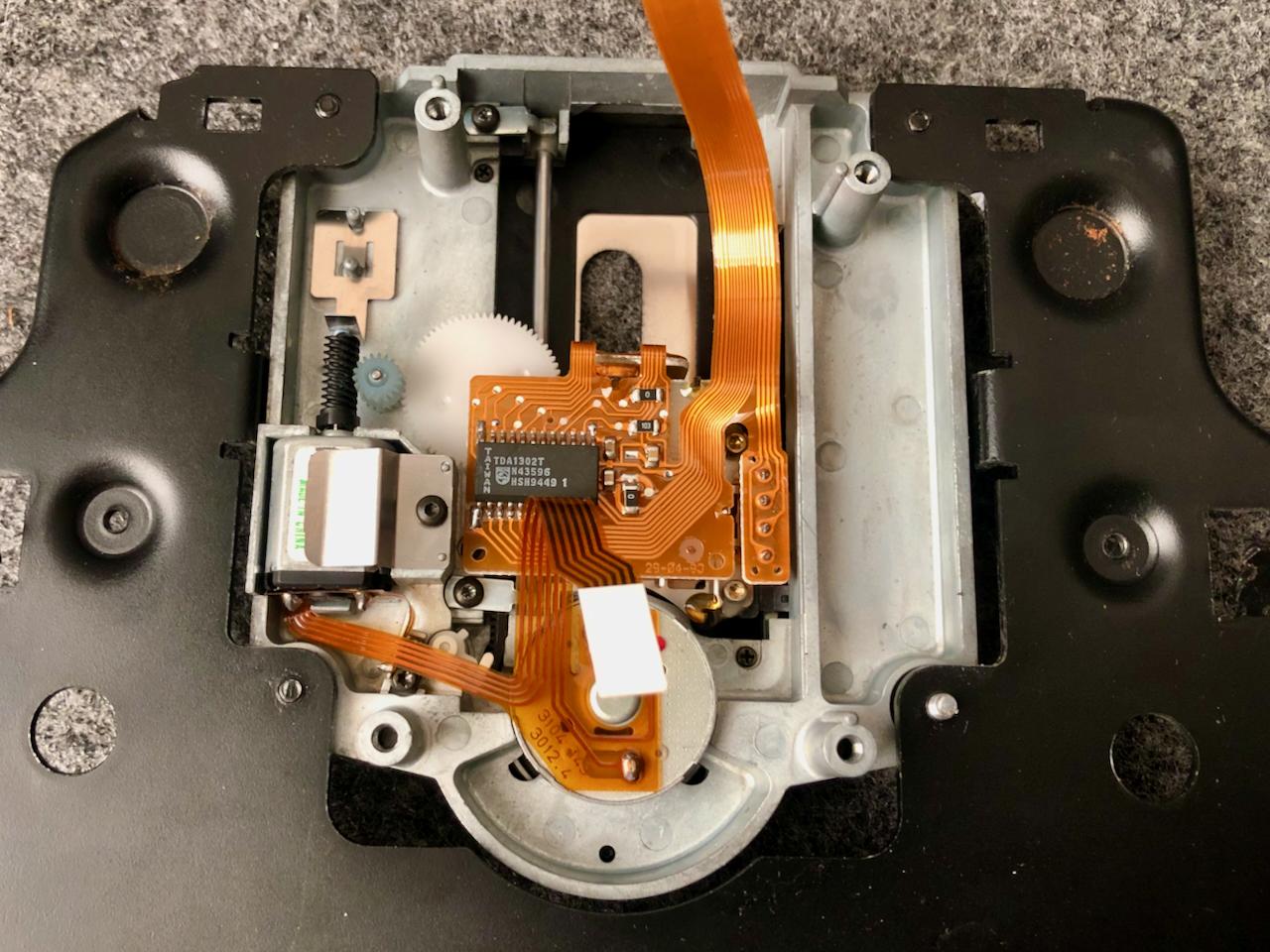
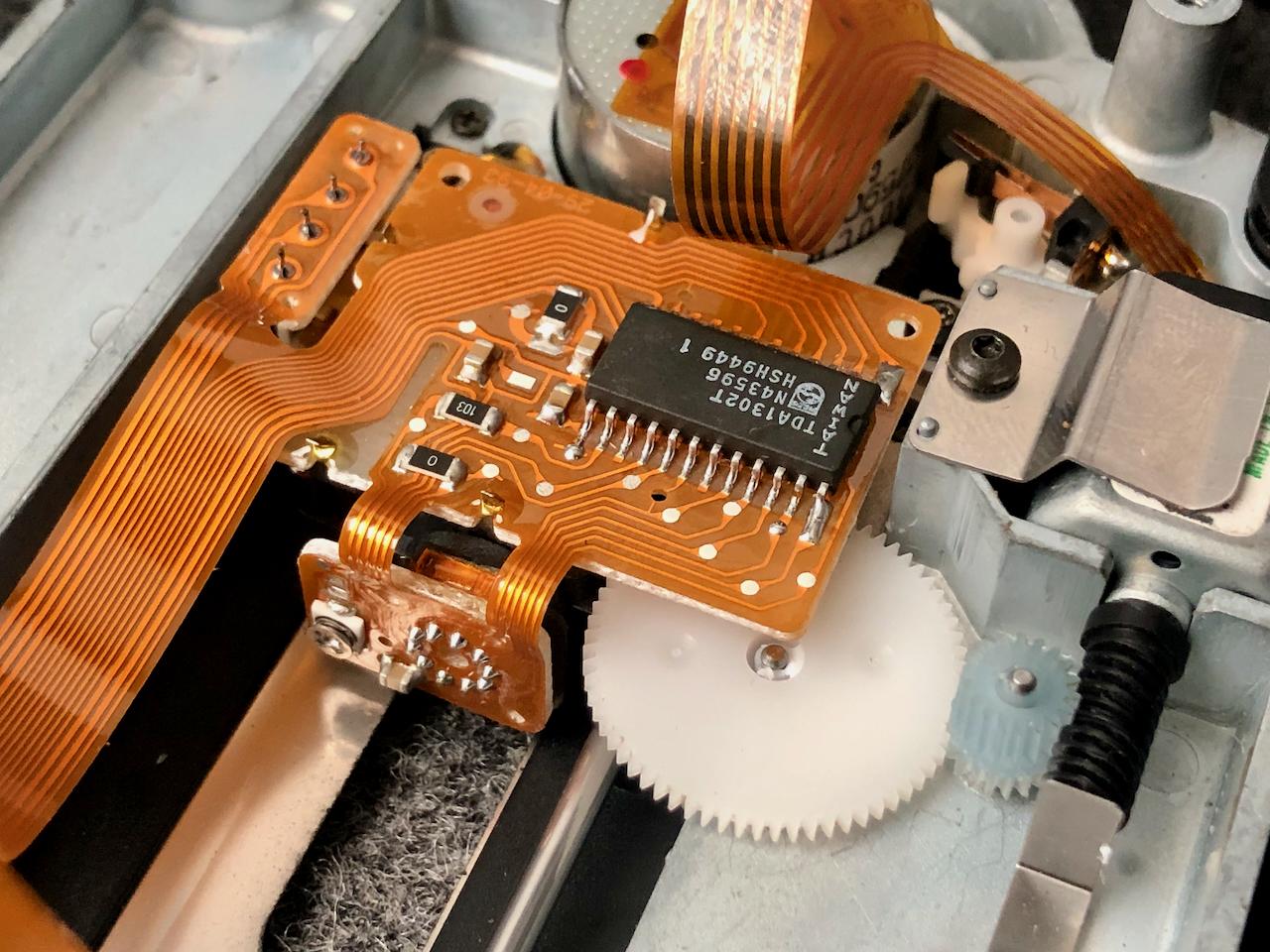
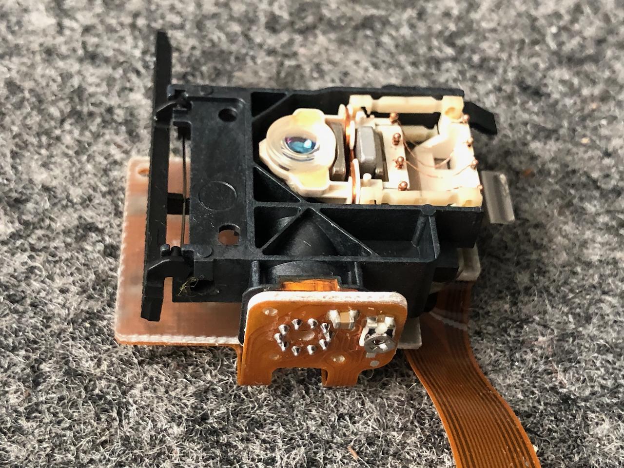
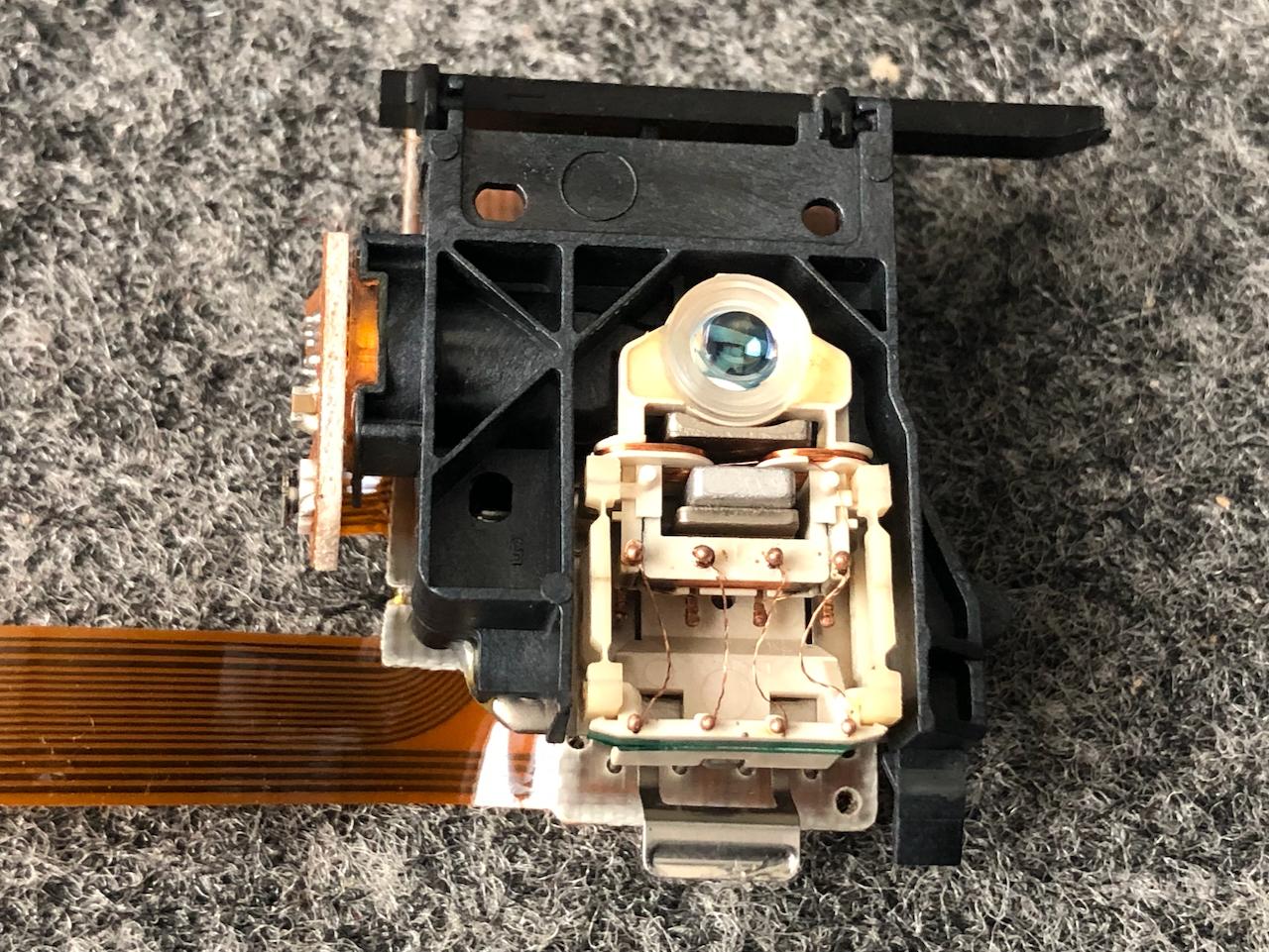
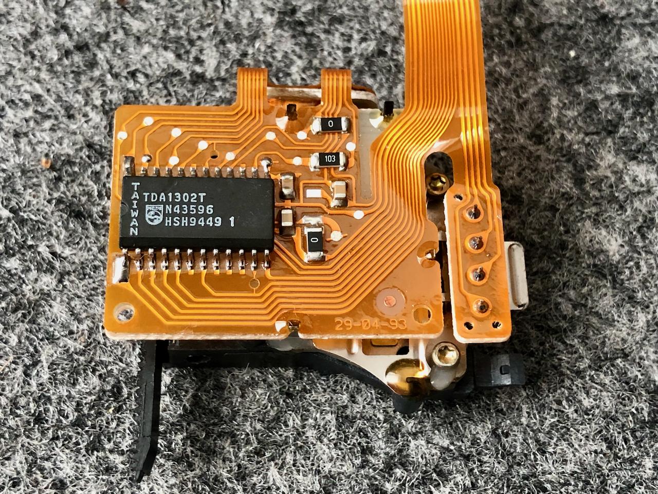
I’ve just removed and dismantled the drive again. It’s a CDM12 IND (Industrial). Looks to have the correct laser pickup?
BTW – just joined as a ‘Silver’ 😃
Thanks Bill!
That may suggest a failed laser precludes the carrying out of the CD tests. Did you replace just the pickup, or the main assembly, with spindle & tracking motor?
I see both the pickups, and the assembly are available for very little money, yet others are multiple times those prices. Does anyone know the difference, given they haven’t been manufactured by Philips in years AFAIK?
I have read the new ones are less reliable, and more fussy in terms of media.
Thanks 🙂
Sorry to hear that Bill 🙁
I wonder what has failed, given your working unit has been powered down, and was found to be faulty on powering up. Maybe a pronged period of no power, followed by power-up causes a spike / damage?
Did your spindle motor move at all in any of the tests, even a touch, or was it completely stationary? I would be interested to know the start sequence for the drive. I’m wondering, if the laser is faulty, then the spindle motor won’t receive any power.
But then, would a faulty laser also result in no response to the tests, like 44 and 45, which just move the pickup? I note that test 42 states: ‘Turntable motor starts, and the laser switches on and goes into starting position.’ Is this a simultaneous action, or sequential?
So many questions!
Thanks for the replies 🙂
The drive is the later Philips type, with straight-line tracking. I checked the transport screws, they were in place and were fully unscrewed.
I removed and dismantled the CD drive, then cleaned the lens & mirror as per: https://www.youtube.com/watch?v=qXGubkovMEE
The lens and mirror actually looked quite clean. There was no hardened grease on the tracking drive, and everything is moving freely, including the pickup along the guide rail. No bulging capacitors, or any other visual anomalies on the two boards.
Reassembled, and it’s still no different, returning error 2 when pressing CD in Test Mode. Before reassembly, I manually moved the pickup to the outer most position. When pressing CD, the pickup moved to the inner most position, so it’s fair to say there is at least power! The spindle motor hasn’t once moved though, not even a blip.
I am wondering if someone has been in here before… One of the four screws that secure the drive mechanism to the steel chassis is silver, the other three are black. I could also see what appeared to be some telltale wear to the coating on the black screws.
@billbriscoe I agree, they are great units! I was mightily impressed with the first one I acquired. I’ve just never really noticed the Century before now, thinking (erroneously) they wouldn’t sound that great. How wrong I was! My Mother who’s in her 80s is now enjoying her expanding CD collection. It’s easy for her to use, after I made up some cheat-sheets to guide her 🙂Hi – many thanks for the replies 🙂
I have the manual with the test procedure, why didn’t I check this first?!
OK – when in test mode and pressing CD, the display briefly reads 1, then settles at displaying 2, which according to the manual is a focus error. None of the other test modes for the CD give any output. Test modes 40, 42, 43, 44, 45, 46, 47, 48 and 49 do nothing, all I hear is a very quite ‘blip’ from the mechanism, and that’s it. I viewed the lens through my phone, and I couldn’t see anything on my phone screen when trying test mode 40. I’m wondering – if a focus error is returned from the test mode, does that mean none of the other test modes will work?
Thanks again!
An update…
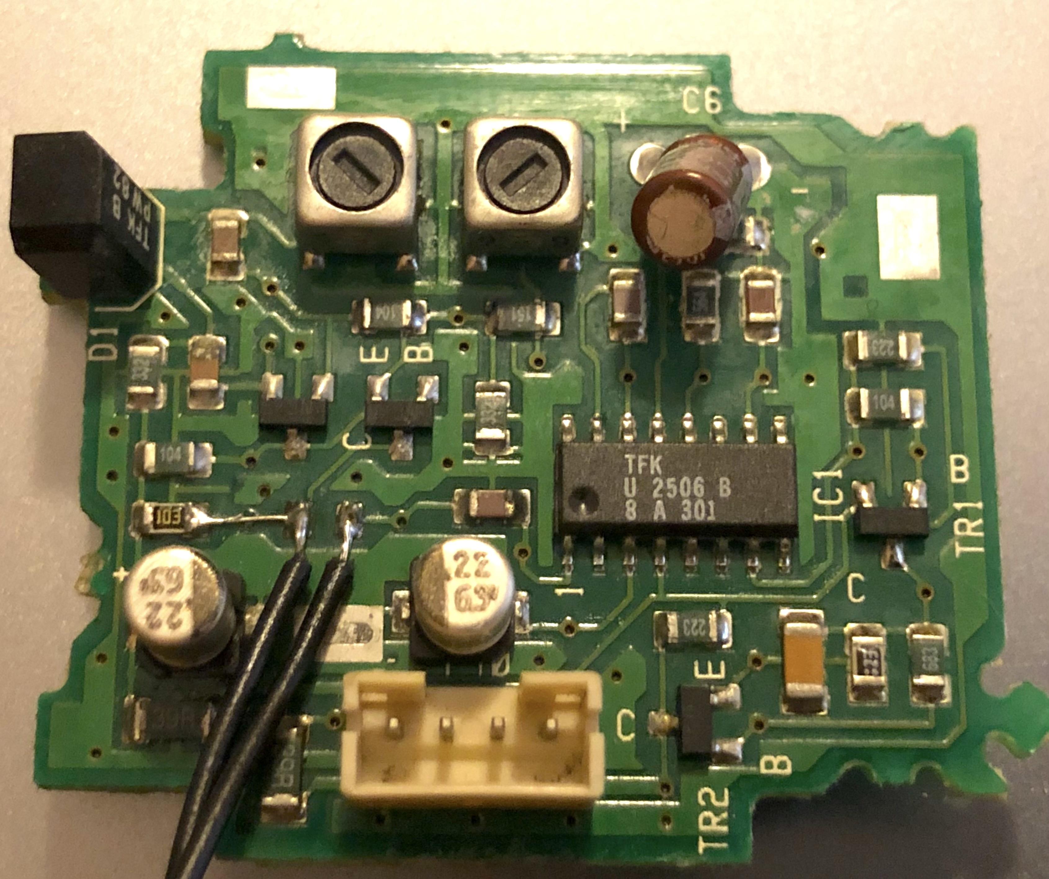
Replaced R13, C1 & C4 with SMDs. Powered it up, pressed ‘Standby > Sound > 1 > Store’ on the unit itself, which results in the number 1 briefly making an appearance on the display. Fully expecting no response as per when pressing anything on the BL1000 – I pressed Radio, and it sprung to life – it’s working! 😃
I wonder if the break in the track between R9 & R13 caused an over-current situation in R13?
Anyway, I’ve since removed & disassembled the gearbox & door slider, removed the old grease & applied new grease (Molykote EM-30L), and a new belt. The mechanism is now running very smoothly.
I’ve been enjoying my old CDs again, with the unit set up in my bedroom. There’s something about having a smaller unit like this, set to the side playing music in the background (and LOUDER when one desires!), without having / wanting to fire up the main audio system.
I’ll carry out a couple more jobs, like cleaning the CD lens / mirror, cleaning the fabric frets etc, before handing it over. This is staying in the family, but I’ve become so attached to it, I’ll be getting one for myself!
Thanks @Madskp!
I cleaned the board up yesterday, and carried out a few (amateur) tests!
R9 revealed itself as not to have blown its top. I think it was the detritus making it out to be headless. It tested out just over 10K, all good. However R13 was O/C. The track between them was also O/C. Yes, there was some corrosion. I bridged the two resistor pads with a hair’s breath wire! This required a very steady hand, and it’s a good job I’m short-sighted! 🤓
I strapped in a couple of resistors via some wire to make 820K as good as. Alas, it’s still not working. Of the two 22uF caps – in circuit C1 is measuring 12.2uF, and C4 16.4uF. Neither are S/C. I’ll place some on order!
Thank you all!
I see BV14 is an ‘updated’ 4K / Android version of BV11. But I’ve read a number of issues with BV14, not least the Android implementation. I’m looking for a 40″ TV, and 4K won’t be anywhere near a priority. So will a BV11 prove to be a more stable / reliable option over BV14? Thanks again 🙂
Thanks – that made for informative, and educational reading!
I’ve just discovered there are four versions of BV11, Mk1 – Mk4. Should I be looking for any particular mark, are there differences that are notable, and enough to sway purchasing one mark over the other?
Thanks again 🙂
Hi MM & Graham
Thank you for your replies!
Great to hear I won’t need an aerial for this to work. That alone has swayed me!
I wonder if anyone with a BV11 also has a plug in power meter to hand? I’d love to know real-life energy consumption, and if P.Mute has any effect? I use an Ecosavers energy monitor which is accurate down to a tenth of a watt.
Regards the audio – from what I’ve read, I think BV11’s speakers will be fine for my needs. I thought about adding a subwoofer to fill out the lower end.
I will research more about PUC which is completely new to me.
1 April 2024 at 23:58 in reply to: BM6500 / 7000 Powerlink – Attenuated Speaker or True Pre-Amp Out? #54010Thanks!
I just found the schematic, and yes I see now, the pre-amp outputs are fed through 100Ω resistors to pins 3 & 5 of the Powerlink sockets.
-
AuthorPosts


