Forum Replies Created
-
AuthorPosts
-
Llurkio
BRONZE MemberHi John, yeah that sounds like a plan, I’ve not had any experience with 3D printing so I’m unsure of the integrity of the formed pieces, but the joint between the wheel axle and drive shaft is going to be quite stressed (for it’s size)- might I suggest putting a small tight circlip over the joint, I believe they came out of the factory like this.

And, if you do find a supplier of new belts, please, please let me know where you get them, one of my machines has several splits in the belt and has a piece of mylar (?) glued underneath, it works but not as smooth as I’d like.
If you’re unable to source new clutch washers, PM me.
Tim
Llurkio
BRONZE MemberHi John
As there’s been no suggestions for you, I’ll try to offer my thoughts.
I’ve done a couple of these and luckily mine didn’t have your problems (mine was clutches), so would it possible to glue some tight fitting plastic pipe over the tractor wheel axles and pin them in place with some very hot pins pushed through ?
As for the other side, drill through the metal shaft and do the same using something like an “R” clip (removable, if needs be) ?
I really don’t know if this is a practical solution, but I’d be looking at something along these lines initially – otherwise, keep an eye open on Ebay for a scrap machine (but I suspect this might just have the same problem !)
TimLlurkio
BRONZE MemberHi Paul,
Firstly I’m probably NOT the best person to ask for advise, I’m an amatuer that “dabbles”, I’ve had no formal training so I can’t really be of much help, but I usually start with a long good look at the boards, looking for anything that doesn’t seem quite right, discoloured boards, bulging caps, dry joints etc.
I do note that you mention “Beocenter”, mine was a “Beomaster”, two very different machines. I put as much information as I could in my write-up, beyond that, I cannot be of much help. However, I do have an old Beocenter 4600 that I was planning to attempt to repair, but I don’t think I’ll ever get around to it, so if you need a machine for spares (and you’re in the UK), this may be an available option for you.
In the meantime, good luck and don’t give up, it’s good to know these old machines are still being used.
TimLlurkio
BRONZE MemberGreat minds think alike Stoobie, the sticky back plastic is already on order !
(I like the mirror finish idea, that could look good too ).
Tim
Llurkio
BRONZE MemberOops, sorry, yes, I’m located in the South West UK, I’m happy to deliver up to 50 ish miles from Bristol at a small cost.
Tim
Llurkio
BRONZE MemberThese have now been sold.
Tim
Llurkio
BRONZE MemberThe control PCBs were found to be identical (the 3500 even had a timer pin – complete with griplet – I think that’s what they’re called), I put the 4500 glass control panel on and every thing appeared to work, I can mange without the timer – I’d never use it anyway.
I gave the 3500 a really good clean inside (it needed it) along with the 4500 nice shiny lid and I may colour the sides white (somehow).
So I have a good working 3500 dressed as a 4500 !
There will an advert soon, a non-working, not complete BM4500 for sale – no glass panel, with a 3500 ‘lid’, with a couple of faults – it may be useful to someone.
Llurkio
BRONZE MemberI suppose the obvious question then is, will the BM3500 work using the BM4500 glass control panel – despite the loss of the timer functiom ?
Tim
Llurkio
BRONZE MemberMany thanks Martin.
Llurkio
BRONZE MemberWell . . Well. . Well . . . !
Who’d have thought it from B&O !
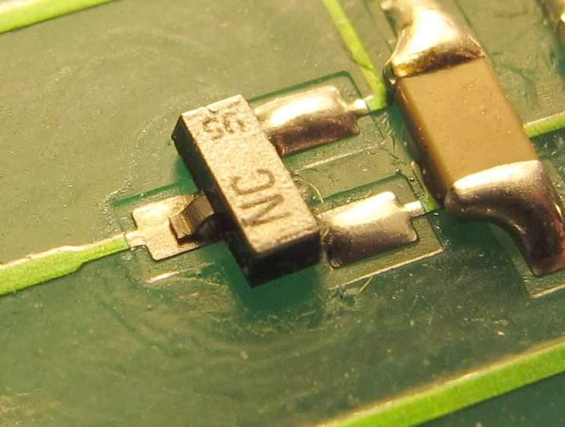
In my last post, I was having concerns about “Tape 2” not responding, I was looking at the PCB with the intention of replacing TR24 (BF840) with some 8x magnifying spectacles but keeping the focus is difficult at times, so I took some photos to examine on the big screen, this is what I found !
It was a dry joint in the most literal sense.
“Tape 2” was a little temperamental initially when only one channel was working, but this fault was low priority at that time. I’m guessing that the original owners may have had problems with this (?) and maybe this is why I was able to buy it at the low price I paid.
So some very careful soldering, then reassembly and hey presto ! Everything works perfectly !The 4x diodes (bridge rectifier) were replaced with long legs and a small piece of brass glued to the bodies of the diodes (being careful NOT to touch the legs ) to act as a heatsink.
Many thanks to ‘RaMaBo’ for the info, but I couldn’t even get “Tape 2” to light up at that point, I knew the problem was not my ignorance ( for ignorance, read ‘stupidity’ !).
So now I have a beautiful Beomaster 4500 in very good condition with everything working.
One very pleased Tim
Llurkio
BRONZE MemberSince the update I’ve realised my own stupidity ! (It must be an age thing – this is what I’ve got to look forward to in my retirement !)
I’ve been trying to “blame” the EEPROM/battery for not remembering the settings when being put into standby, I found out that these settings have to be stored manually ! Oops.
Anyway, that now done and a full test later revealed one remaining fault, the “Tape 2” function doesn’t work – I’ve tested this by using a hand held screwdriver and touching the solder post (on the control PCB – bypassing the sensi-touch panel) and still no luck.
(I’ve also confirmed this by using the panel from a good working machine, and all worked OK then)
This is going to be tricky as the components are tiny (I believe they are called “surface mounted”? I’m thinking it’s TR24 (BF840), has anyone got any other ideas and/or thoughts about testing this theory ?
TimLlurkio
BRONZE MemberSuccess !
The STK4151V power amp was replaced and also all the small transistors between the power amp and the speaker connections, one was found to be dud.
I have not yet replaced the bridge rectifier diodes, but will do so as soon as they arrive (I’ve ordered the same as is already in the machine (1N4002)), I will mount these with ‘long legs’ and try to find something to clip over them to act as a heatsink.
Although both channels are working now, I’ve found that after every time it’s put into ‘standby’, it comes back on at full BASS and minimum TREBLE which needs to be reset each time, is this something to do with the EEPROM memory ?
So my questions are:
Is it OK to replace the EEPROM battery without losing the basic functions, if so, should this be done with the machine on (to remember the settings) or to have the machine switched ‘off’ ?
Secondly, I bought this machine as used, and therefore do not have a comprehensive owners manual, so is it possible to do “facory reset” on the EEPROM ?The word “CODE” does not appear.
Any thoughts or suggestions would be helpful.
TimLlurkio
BRONZE MemberThanks Christian for those words of encouragement – it helps to know I’ve got people ‘looking over my shoulder’.
Luckily I have a ‘scope so that made tracing the fault easier.
The IC3 (STK4151V) replacement has already be ordered, as is the recommended (by Christian) tape, I’ve also ordered replacement transistors (BC546, BC547, BC557) bewteen IC3 and the speaker connectors (they only cost pennies !), but don’t know if I should replace these, I’m wondering if they were likely to be “spiked” and destroyed ? I could remove them for testing, but then I just as well put new ones back in !
Glass control panel has already been cleaned up and ready for re-fixing, awaiting new tape !
One final question regarding 4 x diodes which make up a bridge rectifier, (D10, D17, D19, D27), these have been running so hot, they’ve discoloured the PCB, my guess is that they might be a bit “tired”, I was thinking about replacing these with some higher rated diodes AND mounting them with longer ‘legs’ so the body of the diodes are away from the PCB for a bit of ‘air cooling’, – or is the PCB supposed to act as a heatsink ? I’ve got some UF5404 rectifier diodes (left over from a previous repair), would these be a suitable alternative, given that they’re rated at 3a and high(er) frequency, my logic is that these diodes wouldn’t have to work so hard?
Any thoughts anyone ?
TimLlurkio
BRONZE MemberWell . . . . .
So far I’ve managed to trace a stereo signal going into IC3 (STK4151V) on pins 1&18, but only one channel coming out on pin 13, nothing on pin 10! So I think I’ve found the culprit.
My concern now is, what could have caused this ? Do I look for other faults, or just replace STK4151V and hope that all will be OK ?
Tim
Llurkio
BRONZE MemberThank you SO much Christian, it’s given me something to work on/look at, it’ll take me a few days to ‘get my head’ around this information and do anything practical (I’m not an electronics engineer – just a very careful amatuer), I don’t want to rush anything to make things worse ! (And I don’t have/use powerlink – yet, this is somethiing else I need to look into ).
Oh, I initially cleaned the glass panel insides very carefully with minimal IPA (and a plastic scraper) – it seemed to work fine, and many thanks for the infomation regarding a suitable adhesive, I’ll definately get some of that (I wouldn’t have used epoxy anyway – I realised that’s not the best solution).
Thanks again, I’ll keep you posted ! Tim -
AuthorPosts

