Home › Forums › Product Discussion & Questions › BeoSound › BeoSound 3200: is the AUX connection IN and/or OUT?
- This topic has 17 replies, 8 voices, and was last updated 3 years, 6 months ago by
-
AuthorPosts
-
5 July 2022 at 10:22 #35983
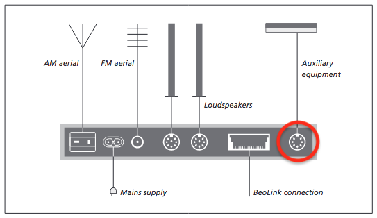
I want to use a BeoSound 3200 for recording from CD’s. So I have a CD playing on the BeoSound 3200, and I have a cassette deck connected to the Auxiliary connector on the right (see picture), to make the recordings.
My questions
- Will this work?
- What is the pin configuration of the auxiliary connector? (For L & R out, and GND)
Location: The Netherlands
Favourite Product: BeoSound 9000
My B&O Icons:
5 July 2022 at 11:40 #35984Die_Bogener
BRONZE MemberJust guess…. B&O compatible, not standard.
Just connect a Beocord 6500 or 7000 … just B&O. It will work on play and record.
5 July 2022 at 12:00 #35985From the BS3000 Service manual, maybe it’s the same for the 3200.
Location: Paris France
5 July 2022 at 12:06 #35986Not able to test it now.
I assume that this will work with non-B&O devices as well.However, you’ll need to control the devices manually.
https://www.beoworld.org/faq_view.asp?id=28
MM
Location: Flensborg————Danmark
5 July 2022 at 12:41 #35987However, you’ll need to control the devices manually.
Maybe I’m wrong but pin 6 and 7 not being connected he will miss the Datalink protocol and therefore, will need to control the cassette deck manually anyway, B&O or not.
Unless B&O restored the datalink protocol on the 3200?
Location: Paris France
5 July 2022 at 12:48 #35988You are right, I assume.
Unless KolfMAKER want to record a lot, this probably will be a minor problem.
MM
Location: Flensborg————Danmark
5 July 2022 at 12:57 #35989Thnx to all, this is a great experience to have such great responses so quickly on the BeoWorld forum!
Additionally I should mention, the external recorder is non-B&O. It will be a vintage Nakamichi 600 cassette deck.
Not being able to control this external recorder as a B&O device is not an issue. For me it is just important that there is a L & R channel OUT, that I can pick up via the Auxiliary connector on the back of the BeoSound 3200.
So from all your information I conclude it is possible and will work. As long as I use:
- Pin 1 > Left out
- Pin 2 > GND
- Pin 4 > Right out
As mentioned and described in the response and picture of Matador.
Thanks!
Location: The Netherlands
Favourite Product: BeoSound 9000
My B&O Icons:
5 July 2022 at 13:01 #35990So here’s an additional question …
Is it possible to simultaneously:
- Connect a turn-table via the Auxiliary Pin 3 & 5 and play vinyl
- And connect my cassette-deck via the same Auxiliary Pin 2 & 4 and record the music from the turn-table
Is this possible?
(Assuming of course that a made a splitter cable which can handle that)
Location: The Netherlands
Favourite Product: BeoSound 9000
My B&O Icons:
5 July 2022 at 13:23 #35991I don’t know!
But why would you do so?
Why not just connect the output of the turntable directly to the 600 deck?
MM
Location: Flensborg————Danmark
5 July 2022 at 14:16 #35992Why I would do so > Cause I need the turntable and the cassette deck connected to the BeoSound for both recording, as well as for playing via speakers connected to the BeoSound.
Is it possible to simultaneously:
- Connect a turn-table via the Auxiliary Pin 3 & 5 and play vinyl
- And connect my cassette-deck via the same Auxiliary Pin 2 & 4 and record the music from the turn-table
Comment: I would say so, cause normally with RCA connections this AUX would be two RCA connectors for Line IN, and two RCA connectors for Line OUT. So, isn’t the DIN a combination of these sets of RCA connectors in one plug?
Question
Please comment on my ‘Is it possible to simultaneously …’ question.
Location: The Netherlands
Favourite Product: BeoSound 9000
My B&O Icons:
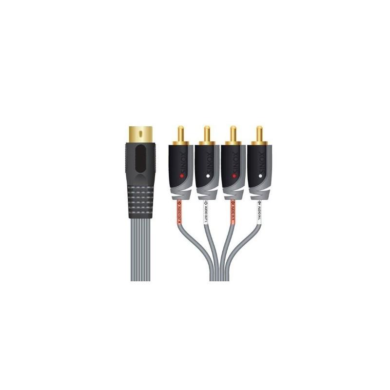
5 July 2022 at 16:50 #35993Hi, Steve provides such a connector:
Maybe ask him directly if it will do what you need.
Location: Netherlands
My B&O Icons:
5 July 2022 at 19:21 #35994Hi,
Yes, this cable provides simultaneous audio in and out, so whatever is playing on the speakers (CD, radio, A. Mem or Aux) can also be recorded via the Aux output using this cable.
Kind regards, Steve.
Location: The cable workshop, England
Favourite Product: Beosystem 72-23
Signature: Cables, friendly advice and great ideas for connecting Bang & Olufsen! Ask any questions at https://soundsheavenly.com to get the best from your B&O! Please visit my B&O YouTube channel at https://www.youtube.com/soundsheavenlycables
My B&O Icons:
6 July 2022 at 14:21 #35995Thanks for your replies guys!
I mainly wanted to know if the pin 3 & 5 and pin 2 & 4 would work simultaneously. So thanks for confirming.
Concerning the cable … the one I need will look a little bit different. I need to split from DIN to a) mini-jack and b) RCA female. But that’s no issue for me, to make one myself.
Location: The Netherlands
Favourite Product: BeoSound 9000
My B&O Icons:
26 July 2022 at 11:50 #35996Just to be sure …
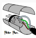
When looking at the picture you added about the pin-numbers and what they mean:
- Is the view of this picture, the male connector from the backside (soldering side)?
- Are the ground wires (of the input and output cables that I need to combine to the DIN), combined on PIN 2?
Location: The Netherlands
Favourite Product: BeoSound 9000
My B&O Icons:
26 July 2022 at 14:38 #35997- Is the view of this picture, the male connector from the backside (soldering side)?
It is not (as often) specified in the Service manual, sorry.
- Are the ground wires (of the input and output cables that I need to combine to the DIN), combined on PIN 2?
In my experience, they are but you may want it to be confirmed by someone else. Nevertheless, they’re is no other pin available so it must be this.
Location: Paris France
26 July 2022 at 18:25 #35998Is the view of this picture, the male connector from the backside (soldering side)?
It’s female connector from solder side, or male connector from pin side.
I usually scan Peter Pan’s diagrams to check: https://www.hifi4all.dk/forum/forum_posts.asp?TID=32157&PN=1
Location: Warwickshire, UK
My B&O Icons:
28 July 2022 at 10:29 #35999Thanks for referring to Peter Pan’s diagrams Guy, that made it clear!
I like the visual way of understanding the pin layout. In the end, it’s easy to make a mistake if you don’t understand the interpretation of sides: male/female and pin/hole side or solder side.
So a picture like Peter Pan is using, helps a lot:
Location: The Netherlands
Favourite Product: BeoSound 9000
My B&O Icons:
29 July 2022 at 15:01 #36000Notice to DIY-ers: DIN connectors often have the pin numbers embossed in the plastic. So you can check your work.
-
AuthorPosts
- You must be logged in to reply to this topic.


