Home › Forums › Product Discussion & Questions › BeoSound › Beosound 1 (CD version) data link???
- This topic has 47 replies, 7 voices, and was last updated 2 years ago by
B3OHACK3R.
-
AuthorPosts
-
30 December 2023 at 08:30 #51687
Madskp
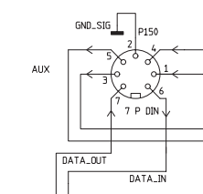
GOLD MemberAs mentioned in this post in another thread https://forum.beoworld.org/forums/topic/beolab-3500-and-1611-converter-settings/page/3/#post-13946 we discovered in the service manual for the Beosound 1 (the older with CD player) that the diagram shows data in and data out on pin 6 and 7 respectively.

However there is no official indication that this Beosound should have any link capabilities, and also the specifications in the start of the service manual says that pin 6 and 7 are not used.

My parents has this model of Beosound 1, so I have been able to do some minor testing to look into this.
I have tried connecting a Beocord 3500 tape player and tried activating it with A.MEM which also activates the AUX connection on the Beosound 1, but no reaction from the Beocord.
Just to see if the pins are even connected I tried to do a voltage measurement with a multimeter on pin 6 and 7 with pin 2 as ground.
Pin 6 is reading 5.1V both in standby and when activating A.MEM. I am not seeing any fluctuations in voltage as I would on a datalink pin when a command is sent.
Pin 7 Is reading 0V both in standby and when activating A.MEM, and also no fluctuations in voltage when a command is sent.
I can’t really figure out if this has any potential use, or if it is just a function that was developed in hardware that newer got Into use in the final product.
In terms of link room capabilities it is indeed only possible to set it in option 0 and 1.
Any thoughts if this is just a dead end or something to pursue?
Location: Denmark
30 December 2023 at 13:15 #51688Strange that the data connections are shown in the service manual. Perhaps they are disconnected internally and/or the software was never made compatible.
If I get a chance this week I will connect my OneRemote radio to my BS1 aux and do some further tests using my adaptor to switch data between the two pins, plus trying the OneRemote in ‘AAL’ mode as if connected to a BL1611 (I don’t think that I tried that before).
Location: Warwickshire, UK
My B&O Icons:
30 December 2023 at 13:30 #51689Madskp
GOLD MemberStrange that the data connections are shown in the service manual. Perhaps they are disconnected internally and/or the software was never made compatible. If I get a chance this week I will connect my OneRemote radio to my BS1 aux and do some further tests using my adaptor to switch data between the two pins, plus trying the OneRemote in ‘AAL’ mode as if connected to a BL1611 (I don’t think that I tried that before).
Thanks for joining in. That would be a good test to indicate if something is ticking
Location: Denmark
30 December 2023 at 14:05 #51690B3OHACK3R
BRONZE MemberYou can see something similar in the BS9000 service manual. On the connector board those pins are labeled with “data” but if you follow the path they are then marked with N.C. (not connected).
Interesting that they actually routed it to the MCU on BS1. What confuses me a bit is that they are marked with “IN” and “OUT”. Datalink is bi-directional / half-duplex. So there are no separate signals for in/out. Could also be that it’s an undocumented service port.
I have no BS1 unfortunately but you could hook up an oscilloscope to see if there is being some data transmitted.30 December 2023 at 16:35 #51691Madskp
GOLD MemberInteresting that they actually routed it to the MCU on BS1. What confuses me a bit is that they are marked with “IN” and “OUT”. Datalink is bi-directional / half-duplex. So there are no separate signals for in/out.
Yes thats a little odd that it is separate IN an OUT. Off course the diagram is only a Block diagram so does not tell the whole story
Could also be that it’s an undocumented service port.
That would make sense in that is undocumented, but on the other hand shouldn’t it be mentioned in the service manual of all places.
I have no BS1 unfortunately but you could hook up an oscilloscope to see if there is being some data transmitted.
I have no oscilloscope at this point, but might end up getting one and see if I can learn something by using it 🙂
Location: Denmark
30 December 2023 at 16:41 #51692Madskp
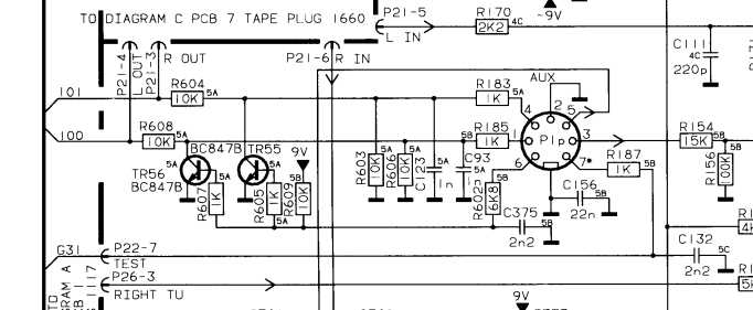
GOLD MemberJust remembered that the Beosound Century that also does not have datalink.
It has the connections in the DIN connector for PIN 6 and 7 are wired like this:
G31 ends at a pin on the MCU called TEST. Could it be that the Beosound 1 had a similar circiut?
Location: Denmark
30 December 2023 at 16:54 #51693silou
BRONZE MemberIt’s not entirely clear to me.
Is the BS9000 data pin functional or not?30 December 2023 at 17:03 #51694B3OHACK3R
BRONZE MemberIt’s not entirely clear to me. Is the BS9000 data pin functional or not?
No, it’s not functional. In the service manual it’s looking like they wanted to implement it but then didn’t proceed with it.
30 December 2023 at 17:08 #51695B3OHACK3R
BRONZE MemberJust remembered that the Beosound Century that also does not have datalink.
Interesting. Could be that it triggers an internal test mode. I remember from the BL7000 that there is also such a test mode pin as well. When you apply a 10 Hz signal it enters test mode.
Also interesting regarding pin 6. If you connect it to ground it will unmute the analoge output on that connector. Haven’t seen that before on other devices.
30 December 2023 at 17:11 #51696B3OHACK3R
BRONZE MemberThat would make sense in that is undocumented, but on the other hand shouldn’t it be mentioned in the service manual of all places.
Could also be for development purpose which would then not be worth mentioning in the service manual. IN/OUT could hint towards a normal serial data transmission. Who knows. Now I’m curious if there is any communication possible on those pins…
30 December 2023 at 18:19 #51697Madskp
GOLD MemberAlso interesting regarding pin 6. If you connect it to ground it will unmute the analoge output on that connector. Haven’t seen that before on other devices.
I could have used that knowledge 23 years ago where I wanted to connect some extra speakers to the Century I had back then 🙂 But interesting that also the user manual says that the AUX on the Century is input only and the specssheet in the servicemanual also says pin 1, 4, 6 and 7 not connected.
I am wondering if it was developed as a way to connect a set of headphones with a special DIN connector as the first generation of the century did not have a headphone jack, but did not end up beeing official in the product.
Location: Denmark
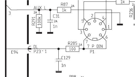
30 December 2023 at 19:01 #51698BS3000 also has no datalink but shows ‘DL’ connections to pins 6 and 7 in the circuit diagram:
Specification pages state pins 6 and 7 ‘not used’
EDIT: But for the BS3000 the manual does also say ‘N.C.’ no connection where it joins the microprocessor interface PCB.
Location: Warwickshire, UK
My B&O Icons:
30 December 2023 at 19:27 #51699B3OHACK3R
BRONZE MemberI am wondering if it was developed as a way to connect a set of headphones with a special DIN connector as the first generation of the century did not have a headphone jack, but did not end up beeing official in the product.
Had another look again. I think there is a mistake in the schematic. If you follow the signal it goes to the tape board. When you look closely those are not outputs but inputs. Also if you look at the audio chip with in integrated multiplexer you see that tape-in connects there while those signals certainly need to be outputs.
So probably those pins are a hidden microphone input for recording something on tape.
30 December 2023 at 19:32 #51700B3OHACK3R
BRONZE MemberBS3000 also has no datalink but shows ‘DL’ connections to pins 6 and 7 in the circuit diagram:
If you follow the signal it goes to P23 (internal 3 pin connector). The other two signals on that connector are Powerlink data Tx and Rx.
P23 connects to P33 on the MCU board. Only pin 3 is connected to the MCU (PL-Tx). The other two are N.C. (not connected). So neither Datalink nor Powerlink Rx for BS3000. I think no audio master ever implemented Powerlink data Rx. I’m still wondering what they had in mind for it.30 December 2023 at 19:39 #51701Madskp
GOLD MemberBS3000 also has no datalink but shows ‘DL’ connections to pins 6 and 7 in the circuit diagram: Specification pages state pins 6 and 7 ‘not used’ EDIT: But for the BS3000 the manual does also say ‘N.C.’ no connection where it joins the microprocessor interface PCB.
Might be something like the BS9000 where the Plug PCB is prepared for the feature, but the functionality not implemented in the end for some reason (cost, time, etc.??)I think there is a mistake in the schematic.That would not be a firstSo probably those pins are a hidden microphone input for recording something on tape.
Yes that feature also seems likely given that the Century could record on tape
Location: Denmark
31 December 2023 at 19:50 #51702Madskp
GOLD MemberI think no audio master ever implemented Powerlink data Rx. I’m still wondering what they had in mind for it.
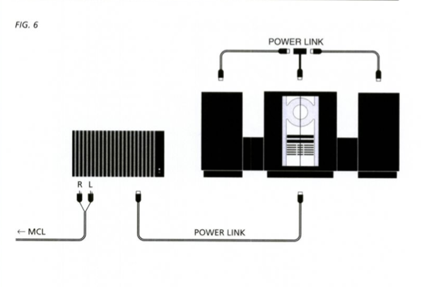
My best guess as also noted in the Beolink Active thread is for use with the ML/MCL converter where powerlink to MCL is also possible as shown in the ML/MCL user manual. For this sceneario commands from the link rooms has to be recieved through the Power Link connection.
However it might not work / being fully implemented on all Powerlink products, and definitely not the Beolink active as I tested in that other thread.
I guess it might have been a kind of a transitional feature when Beocenter/Beosystems/Beosounds began not having built in amplifiers to keep backwards support for the MCL link systems. However as soon as ML became standard in the music systems this feature might have been kind of redundant.
Location: Denmark
1 January 2024 at 12:02 #51703If I get a chance this week I will connect my OneRemote radio to my BS1 aux and do some further tests using my adaptor to switch data between the two pins, plus trying the OneRemote in ‘AAL’ mode as if connected to a BL1611 (I don’t think that I tried that before).
I experimented with various permutations of settings yesterday. I tried the OneRemote radio in various different cablelink ‘modes’, both for normal datalink and AAL and tried most of the source triggers (incl video, audio and PC). Each mode was tried with data to pin 7 and then separately to pin 6. There was no response in any of these setups.
Location: Warwickshire, UK
My B&O Icons:
1 January 2024 at 18:47 #51704Madskp
GOLD MemberIf I get a chance this week I will connect my OneRemote radio to my BS1 aux and do some further tests using my adaptor to switch data between the two pins, plus trying the OneRemote in ‘AAL’ mode as if connected to a BL1611 (I don’t think that I tried that before).
I experimented with various permutations of settings yesterday. I tried the OneRemote radio in various different cablelink ‘modes’, both for normal datalink and AAL and tried most of the source triggers (incl video, audio and PC). Each mode was tried with data to pin 7 and then separately to pin 6. There was no response in any of these setups.
Thanks for taking the time to test this. I think we can begin to rule out datalink as the format for this data in and out connection if it is actually active
Location: Denmark
2 January 2024 at 11:10 #51705Now that I have my second BeoSound 1 (see here), I wondered if it could be worth making a 7-pin DIN ‘crossover’ cable and joining the two together. Thus ‘audio out’ would become ‘audio in’ in the second, and more interestingly data-out would connect to data-in and vice versa. I don’t have time for the next few days but it could be worth a try!
Location: Warwickshire, UK
My B&O Icons:
2 January 2024 at 11:50 #51706Madskp
GOLD MemberNow that I have my second BeoSound 1 (see here), I wondered if it could be worth making a 7-pin DIN ‘crossover’ cable and joining the two together. Thus ‘audio out’ would become ‘audio in’ in the second, and more interestingly data-out would connect to data-in and vice versa. I don’t have time for the next few days but it could be worth a try!
I a pretty sure that the audio part will work, but more interesting if the data will.
For one thing which commands should be used? But you could try something like Link + CD or AV + CD.
Another thing is that it can only be set to option 0 or 1, so no way to select which is a link room. However if this is/was an attempt of a new type of link system, the role definition might not be the same as in the older systems
Location: Denmark
-
AuthorPosts
- You must be logged in to reply to this topic.


