
Home › Forums › Product Discussion & Questions › BeoLink › Beolink 5000 E-Ink screen repair / mod
- This topic has 32 replies, 14 voices, and was last updated 2 weeks, 2 days ago by
 pilatomic.
-
AuthorPosts
-
5 May 2022 at 11:11 #34596
This thread is meant to be the continuation of this thread from the old forum, to provide updates and support about this mod. As such, this post will mostly duplicate the first post of the original thread.
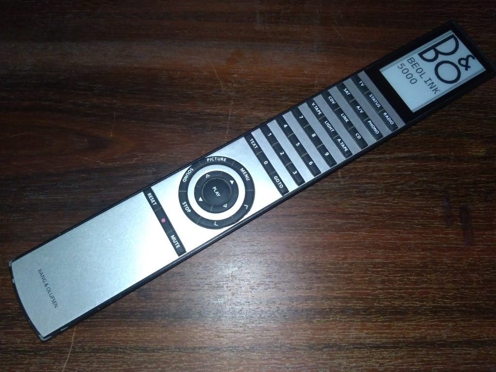
For the last few years I’ve been the owner of (amongst other) a Beolink 5000 with a detached screen. Being an electronic engineer, I’ve spent some time looking for a viable (and cheap enough) way to repair the severed display ribbon cable, and found none.
So a few months ago I’ve spent a fair amount (okay, the vast majority to be honest) of my spare time working on a screen replacement for my Beolink 5000. I was looking for an off the shelf LCD or OLED display panel with roughly the same mechanical dimensions as the original panel, hopefully transparent as well, but again I found nothing, except an E-Ink Display with possibly matching dimensions.
For those who are not familiar with this technology, E-Ink displays are used on E-Reader tablets, have very high contrast without any sort of backlight, only requires electrical power to refresh the display (can keep a picture displayed without using any power), but quite slow refresh rate (it takes a few seconds to display a picture on the screen).
So now having a potential way forward, I started designing a PCB that would fit in the (tight) space available in the Beolink 5000. This PCB would replace the original display controller and interpret the display commands sent by the CPU as if it was the original controller, including displaying “backside-readable” text on the front side. This was actually a bit harder than I originally thought, because a few hacks were used by B&O engineers to optimise the display’s function. For example “frontside-readable” text is indeed transmitted as text to the display controller, but some “backside-readable” characters are written pixels by pixel, so character recognition is required.
The end result pleases me a lot, and restores all the neat 2-way features of this remote, despite the refresh rate being a bit on the slow side
Features :
– Single sided E-Ink display ( that was a given )
– Can display all the original text and indicators (Thanks to Guy for describing to me the behavior of the some indicators on the original display)
– Nice upscaled text display (each character is now using à 29*14 font instead of 7*5 on the original display)
– Standby screen
– Low power : power consumption, and therefore battery life should be similar to the original display.
– Low battery indicator ( that one is new ! )Here is the remote displaying the standby screen :
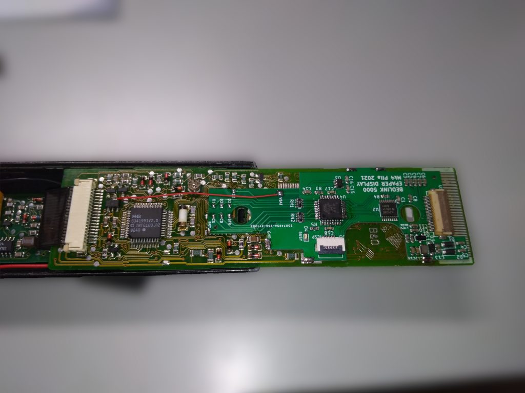
The PCB installed on top of the BL5000 upper PCB, in place of the original LCD controller IC :
The backside is no longer translucent, and is made of a 3D printed part that holds the display in place :

You can see the new display working on this video.I produced a batch of 20 kits, a few of them are still available, at the price of 60€ shipping excluded. ( I can also perform the installation on your remote, please contact me in PM ).
A kit includes :
- The E-Paper display
- The custom PCB
- The 3D printed “cradle” for the display
- A small length of wire to connect to the VBAT signal.
The installation requires some good soldering tools ( including a hot air station and a proper soldering iron ) and skills in fine soldering. The installation guide ( see link at the end of the post ) details the installation procedure. As of now this kit was installed successfully in around 10 remotes.
Useful links :
The page of this mod on my website ( French )
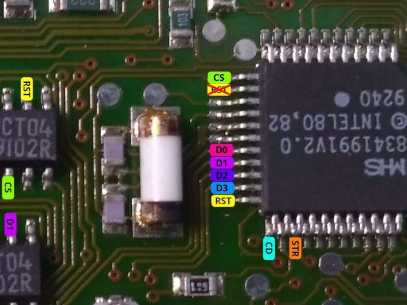
5 May 2022 at 12:32 #34597ERRATUM : Bad wiring diagram in installation manual.
There was a mistake in the section 6, about the signals connections on the MHS CPU. The RST pin was incorrectly placed.
I apologize for this mistake !
If you ran a jumper wire to the wrong pin in an attempt to make the connection according to this diagram, it does not seem to cause any issue, but it is better to remove it.
The installation manual v1.1 contains the correct diagram.
 10 June 2022 at 08:08 #34598
Hi,
I’m interested in this mod (check your Personal Messages).
Kind regards,Yann.
20 June 2022 at 09:13 #34599I don’t even have a Beolink 5000 yet and I’d still buy one of these kits!
Outstanding job! I followed this in the old forum and am genuinely very very impressed with what you have achieved.
tentative question, what would it take to do something like this for the Beo4 – new screens are now down to NOS (New Old Stock) and will one day run out, I think the Beo4 is a corner stone of the B&O handheld controller line up and it would be a shame to not be able to fit new screens to broken models. You could perhaps even use more of the screen real estate with the source wording, add some B&O style icons for the inputs perhaps?
Either way, thanks again for this amazing contribution to the community
19 July 2022 at 09:05 #34601Thank you @YannChris for trusting me with your remote !
Sorry @david656 I didnt see your message earlier. I have yet to own any Beo4, is it subject to the same screen failures ?
19 July 2022 at 10:57 #34600Hi Beoworlders,
Recieved today my Beolink 5000 updated by Pilatomic.
Great job, everything works fine!
The remote control has now a Beo4 look with the screen always on.
Regards,
Yann.
20 July 2022 at 08:59 #34602Hi Pilatomic,
In my experience Beo4 screens do fail, but replacement is actually quite straightforward because connection to the PCB is via a little rubber ‘contact strip’ – a replacement strip is provided with the new screen. There’s no soldering or anything complicated. There’s a replacement thread on the old forum but the photos have yet to re-appear: https://archivedforum2.beoworld.org/forums/p/21827/180453.aspx#180453
I did read a post that B&O were going to stop making/supplying new Beo4 screens, but I didn’t have any problems getting hold of some recently. (EDIT: It was David656’s post just above that I’d read! ?)
30 July 2022 at 01:34 #34603Yeah, not trying to scare anyone, but it is only a matter of time before screen stock drys up. I’ve purchased a new screen on Ebay and fitted, it is quite simple, the BEO4 remote always annoyed me it has that nice big screen and a single line of text in the middle, it would be quite cool if you could one day do an e-ink replacement and fill out more of the screen. 🙂
6 August 2022 at 10:08 #34604Hi Pilatomic, In my experience Beo4 screens do fail, but replacement is actually quite straightforward because connection to the PCB is via a little rubber ‘contact strip’ – a replacement strip is provided with the new screen.
Can you describe me how the screen fails ?
I think there is a good chance the screen are actually fine, just not making proper contact.The “contact strip” is called a zebra strip, it is commonly used for connecting LCD displays, but the drawback is you now have to keep it under mechanical pressure to ensure a proper electrical connection.
Failure to maintain the correct mechanical pressure is, as far as I know, the most common failure mode for those kind of displays.
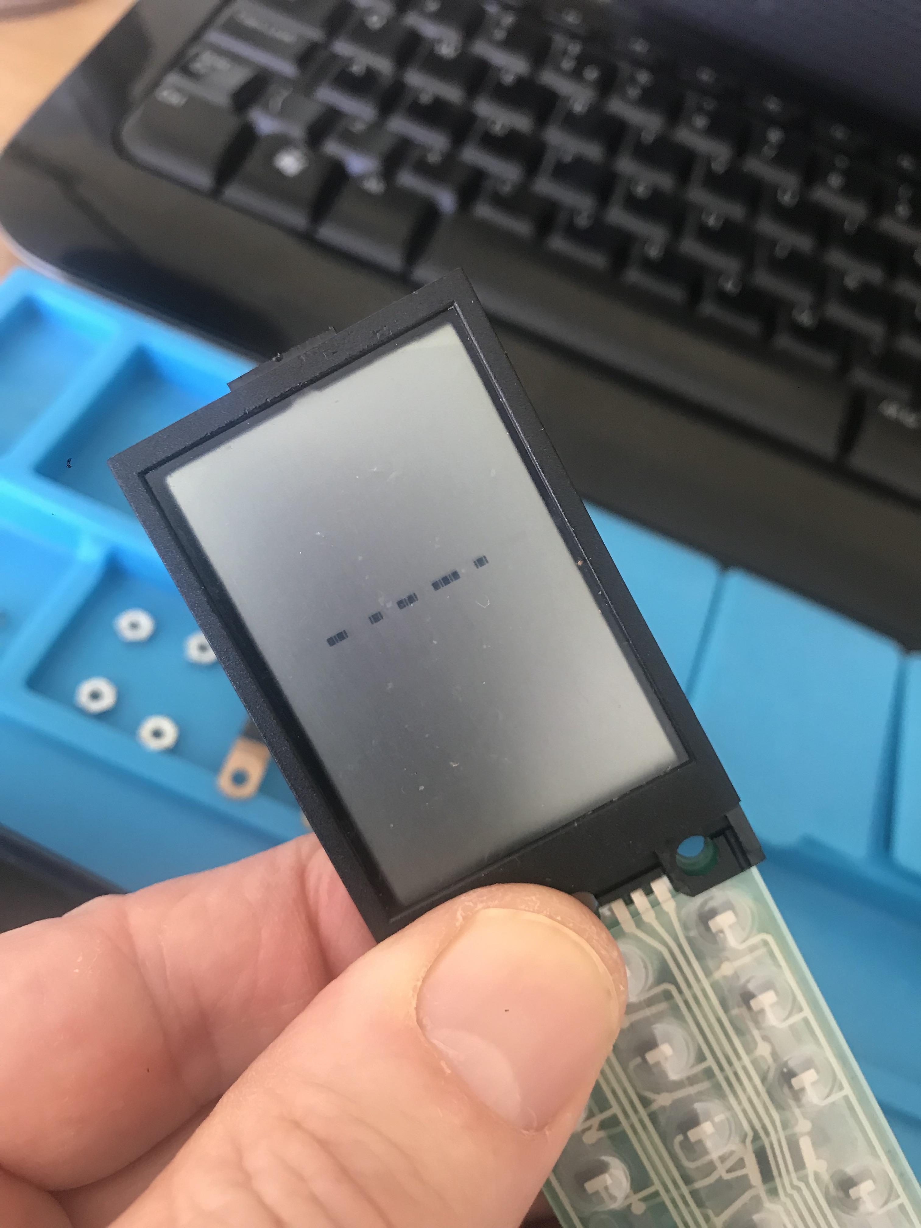
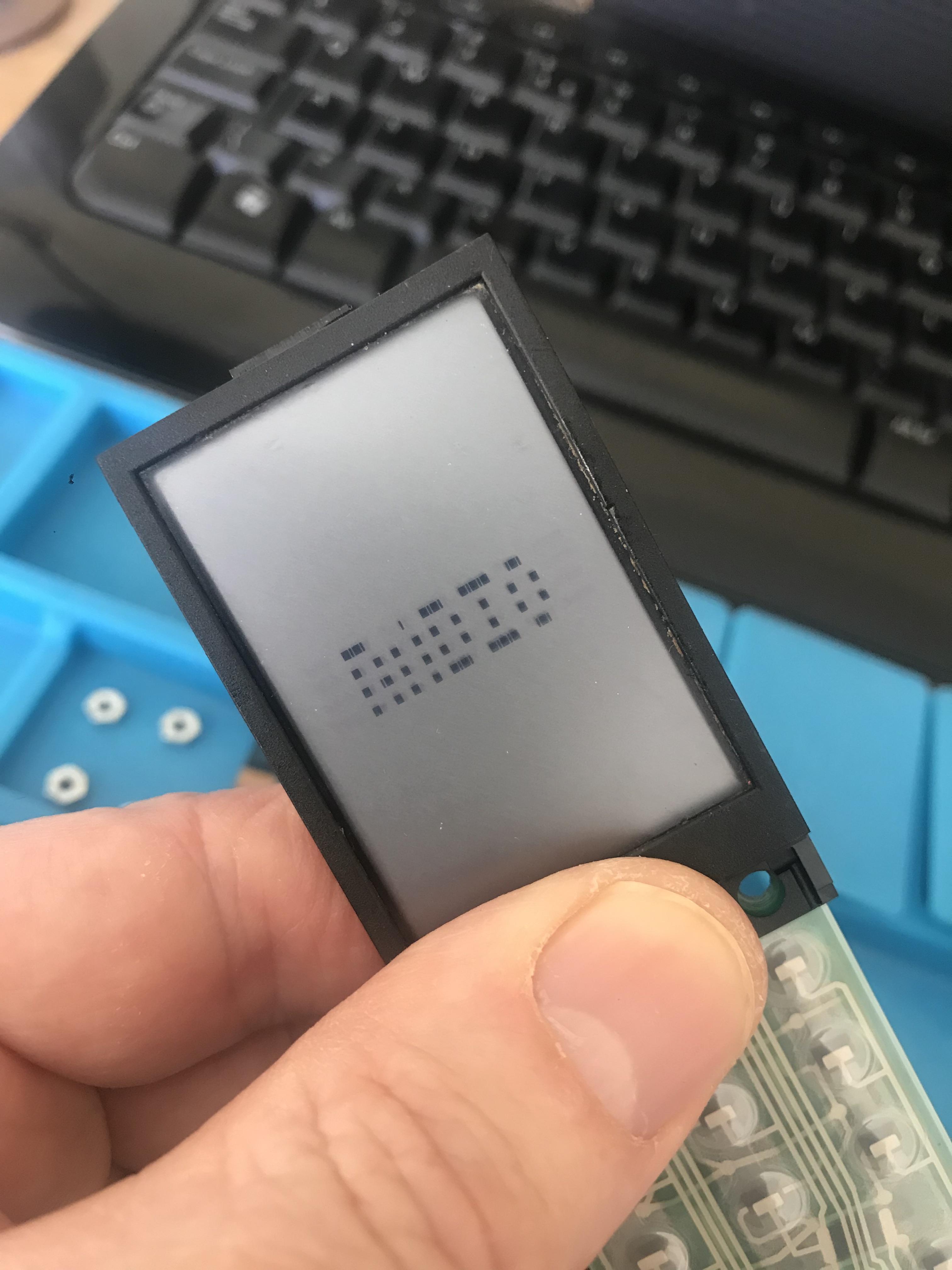
7 August 2022 at 09:22 #34605Usually, it starts with one line of dots that disappear followed by more and more.
And/or the screen contrast fading until being not readable anymore.
And obviously, screen broken or leaking.As you said, pressing the bottom of the screen where the zebra strip is can help sometimes but not always. I tried to carefully clean the strip and tighten it but it didn’t help to bring back some screens to life, so if you have any tip it would greatly help a lot of us I think!
8 August 2022 at 02:32 #34607One full line of pixel missing suggests that indeed one electrical connection to the driver chip was lost, so ordinarily I would jump to the conclusion that the zebra strip is responsible for this, but Guy’s experience tells another story !
I am not aware of other common failure modes for this, although damage to the conductive track on the LCD could explain this behavior.
Now I’m getting really curious about this issue ! If you still have one (or more) damaged screen in your possession, and are willing to ship them to France, please PM me.
8 August 2022 at 12:48 #34606My experience is exactly as matador’s above. I always try to clean/replace/retighten the zebra strip, and clean the PCB where it connects. I have also tried a new zebra strip with the old screen, which didn’t work (same lines missing), whereas a new screen with the old zebra strip did work.
I have probably replaced about 10 screens.
10 August 2022 at 11:31 #34608If you still have one (or more) damaged screen in your possession, and are willing to ship them to France, please PM me.
I do have at least one failed screen in a box somewhere. However, if matador (also France based) has one it may be easier to get from him.
@matador – can you help, or shall I delve into my boxes???10 August 2022 at 11:53 #34609
@matador – can you help, or shall I delve into my boxes???Hi Guy,
I’m afraid I can’t help, I have no spare screen, all the faulty I have are mounted on remotes.
10 August 2022 at 12:04 #34610@matador – can you help, or shall I delve into my boxes???
Hi Guy, I’m afraid I can’t help, I have no spare screen, all the faulty I have are mounted on remotes.
No problem – I’ll dig one out!
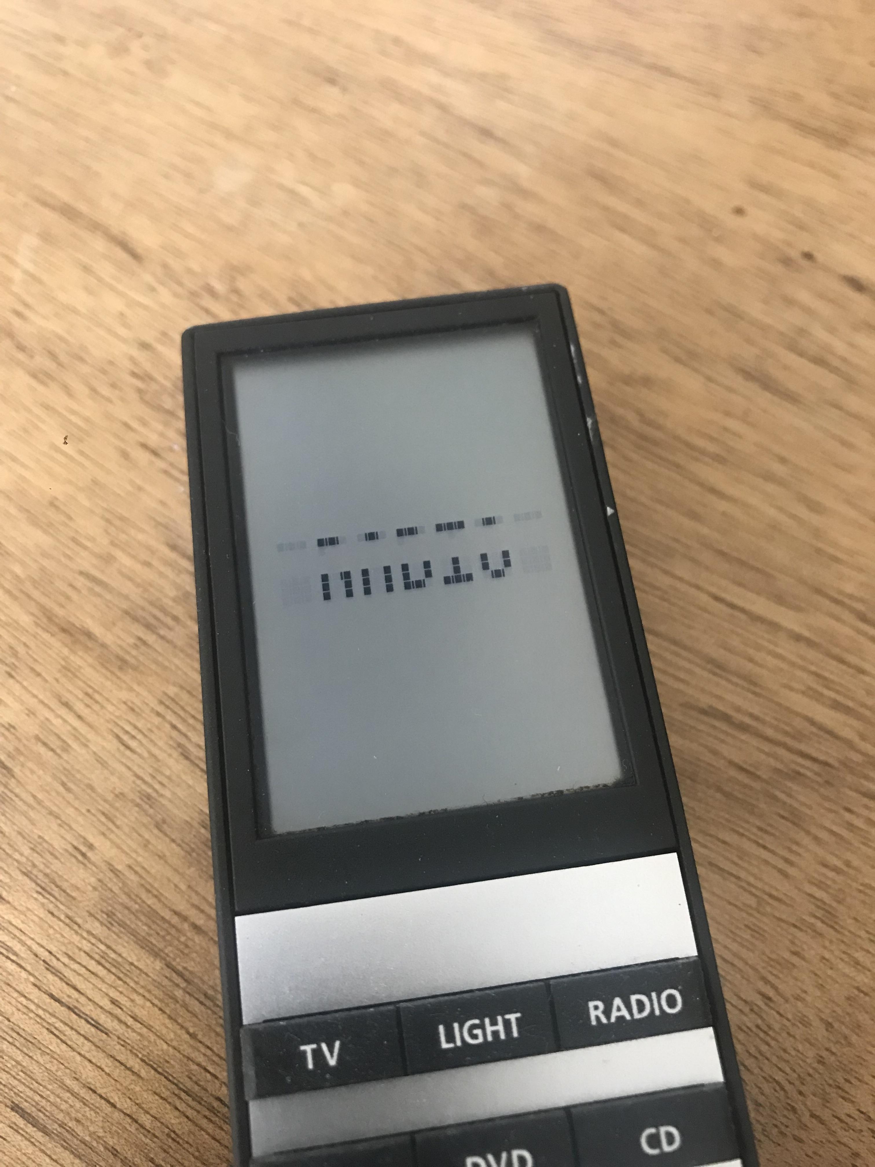
11 August 2022 at 11:35 #34611For info, here are three of my failed screens, two of which are now in the post to pilatomic. Subject to his investigations, we’ll start a new ‘Beo4 Screen Failure’ thread with any findings!
All the following are trying to display ‘RADIO’
 15 August 2022 at 02:11 #34613
Hi Rudi,
Thank you for chiming in on this thread, and hats off for the original design ! I cannot imagine trying to fit that design is such a tight space 30 years ago !
I do understand that the original issue is a degradation of conduction with the ribbon, but as you stated, the complexity of obtaining a new ribbon and the operations required to bond it properly both to the PCB and to the LCD do not make this path viable.
Also the issue is compounded in many cases by the old ribbon cracking, and the LCD breaking free from the aluminum body due to its adhesive foam failing.
However, this does not seem to be the same issue on the Beo4 screen ( cf Guy’s previous message ), as no ribbon is involved on the Beo4, and replacing the zebra strip does not seem to fix the issue. Any idea what might be happening there ?
Best regards !
15 August 2022 at 07:55 #34612Hi
Please read this
https://archivedforum2.beoworld.org/forums/p/13459/194468.aspx#194468
https://archivedforum2.beoworld.org/forums/p/37015/335289.aspx#335289
The display driver address one row or column in the display per track on the heatsealing (the ribbon cable), so when the glue slips on the cable, one row or column is missing.
The glue had a lifetime of 10 years …..
I have contacted Optrex (who produced the ribbon cable) asking them for new ones, so far they have not responded – they see no business for this.
One thing is to get a new ribbon cable – another is to seal this to the PCB and the display
Best regards Rudi
19 August 2022 at 10:55 #34614Is there still one piece available – i would like to built one beolink 5000 (mine doesn´t show anything on the screen, but works).
Best regards
69er
22 August 2022 at 01:28 #34615Hello 69er,
I have assembled a couple more kits this weekend, those are available right now, still for 60€ / piece + shipping.
Please send me a PM with your address so we can arrange the payment and shipping.
Best regards
-
AuthorPosts
- You must be logged in to reply to this topic.