


Home › Forums › Product Discussion & Questions › BeoGram › beogram 8000 TT only
- This topic has 33 replies, 9 voices, and was last updated 3 years ago by
 Glitch.
-
AuthorPosts
-
1 June 2023 at 07:42 #46967
 thomashBRONZE Member
Hello: Got this out of abandoned shed, DIN cable missing and no beocenter either. Primary power xfmr fuse blown, even with replacement unit does not respond. Tried the pull P4 and reseat as per service manual but still only drawing 2W of standby. Apparently a second fuse on secondary which I have not checked yet. Do some pins have to be jumped or grounded on the DIN to make it come out of standby? Thank you.
4 June 2023 at 06:46 #46968Hi, nice find!
No need for jumpers or anything.
These beograms, if not yet restored, all need new electrolytic capacitors and a thorough check for cold solder joints and cracked pcb traces. After this one can investigate the reason for the blown fuses.
Quite the job however, best done by someone with experience. I’m working on the 8000s younger brother 8002 and have often wondered if I bit off more than I can chew.
Location: Netherlands
4 June 2023 at 16:37 #46969thomashBRONZE MemberHello Premiumverum and thank you. Glad to know no jumper needed on DIN connector. The second fuse on secondary side was not blown, only the one on primary side. My idea is to put external regulated supply to the main bus from outside just to see if the uProc will wake up. I have not yet exposed that panel under the buttons but hope to get at it from there. If I can get power to everything, then try volts at Q21 which seems to be main turn on command from the uProc. I fix vacuum tube vintage stuff but do not enjoy working on anything solid state.
4 June 2023 at 21:19 #46970thomashBRONZE MemberI got the entire machine dismantled to expose the main board for service. In the course of tear down, the wires on the DIN connector have nearly all come off. I have studied the diagram of the plug and its little board but would like to see image of intact one or what the colors are in order starting with blue on far side. The diagram is far from clear and does not give colors. I did make a parts list of 12 electrolytics to get as starting point.
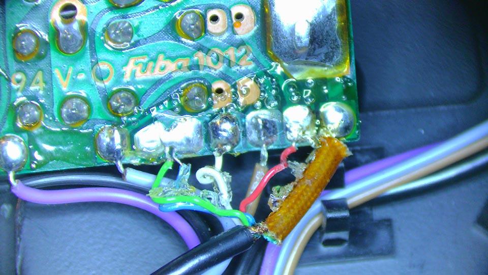
4 June 2023 at 21:38 #46971GlitchBRONZE MemberHere is a picture of the connections on a BG8002.

Hope this helps (and you don’t have to deal with the same glue on the solder).
Glitch
4 June 2023 at 22:33 #46972thomashBRONZE MemberThank you Glitch for image and info. There seem to have been changes though as my audio shields were in the center with hot L and R on either side. Right now having trouble figuring out the relay coil pins for the brown wire. Blue gray and black all seem to be ground but still in the dark as to the layout of this board.
5 June 2023 at 17:59 #46973GlitchBRONZE MemberYep, it looks like the BG8000 board is different than the BG8002 board. It was worth a try…
Debugging is certainly complicated by the muting relay shorting everything to ground. I don’t know the details of what you are trying to accomplish, but sometimes simply removing the relay for debugging can make things easier to understand.
Glitch
5 June 2023 at 18:08 #46974thomashBRONZE MemberIn fact last night I DID remove the relay and determined what is what and am confident I now have the wires right. My plan is to just run the cartridge wires straight out the bottom and bypass the relay. Wonder if anyone out there has a main board available? Might be easier than trying to make this one wake up.
6 June 2023 at 22:34 #46975thomashBRONZE MemberAt the risk of talking to myself, I submit for those interested that I got some response by crowbarring DC supplies into the beogram8000. I used two 9V in series and backwards for the NEG 15 plus a wall wart for the 5V and a regulated adjustable supply for PLUS 15. It now lights up on the display board with 0000 and the arm lights are on. It is pulling 18W from the wall on its own PT. I disconnected the three supplies before sticking my alligator clips in. This is somewhat encouraging so I might buy some electrolytics and see what happens then. Thank you.
19 June 2023 at 19:00 #46976thomashBRONZE MemberHello: Adding to this as things happen; none of them good. I have lost +15V after I nearly had the thing working all correctly. The regulator has +20 going in, +20 on the base to Q18 but zero on the collector output. I am trying to learn how this is supposed to work but baffled. Can I temporarily just send the output of the bridge directly to the load with main power coming up on variac? Thank you.
26 June 2023 at 21:44 #46977thomashBRONZE MemberCan someone provide theory of operation circuit description for tangential drive? I see a xfmr coil connected to first stage of IC3 then another coil bridging final stage of IC3 over to the main drive coils plus there is the brake. I do not understand how all this is supposed to work. This thing began to work after some new capacitors and reflowing of joints but then went south. First the platter began laboring and pulsing then it went super fast and stays that way no matter what commands. Power plug to wall: 100+ rpm. Lost the +15 coming out of regulator; new one same problem. Thank you.
29 June 2023 at 23:07 #46978thomashBRONZE MemberDown in corner near D5 maybe are two afterthought mini boards hanging on for dear life via screw through a transistor. I cannot correlate them to the only schematic I have for a 8000 from vinylengine. If anyone can direct me to a schematic update that includes these, maybe it will help fix my loss of +15V and the out of control 100+ rpm platter that cannot be stopped by anything other than unplug from wall. Thank you.
4 July 2023 at 19:56 #46979thomashBRONZE MemberSince I am not receiving any response or help with this I am going to throw the entire thing in garbage pickup. My friend wants the platter and nameplate to mount as artwork but the rest of it is fast becoming utterly worthless. Good bye to bang and olufsen.
7 July 2023 at 16:54 #46980jfrancis49MemberHello Thomas,
Unfortunately I don’t have the technical expertise to advise you on this. But before I would trash it or give away the platter I would see if you could find someone to service it. Outside that non-working Beogram 8000 turntables still are worth abut on eBay. Someone else might be able to buy and fix it or use the parts to resurrect another nonworking one.
21 July 2023 at 18:41 #46981thomashBRONZE MemberThe latest: I paid $50USD for a new strobe wheel. I can see pulses on pin 12 of IC1 from the pickup I had to also replace. But there is no regulation; the platter is still going way too fast. The next chip in line is inside the uProc oven and will be quite difficult to get at. Still contemplating trashing it. Not sure what should be visible at pin 14 of IC1 but seems like it should be some version of the pulses.
22 July 2023 at 09:13 #46982DillenModeratorYou have already achieved more than most owners could/would.
These Beograms are wonderful decks, but not easy to service as they are so different from everything else, and it’s often seen that several problems and faults are present at the same
time, which can easily confuse matters immensely and make diagnosing difficult.
I suggest you leave servicing to someone with more experience. The results will be great and the Beogram is worth it.Whenever I have problems with my car, I try to fix as much as possible myself, – and I can
do quite a lot myself, really – but every now and then a repair is necessary for which I simply don’t have the knowledge, experience and/or tools and instruments, and in these
cases I bring it in for servicing at a pro car repairshop.
I don’t throw my car away just because a problem comes up that I cannot solve myself.Of course your Beogram can be repaired.
If you are in – or near – Denmark, I’d happily take a look at it.Martin
22 July 2023 at 09:26 #46983Audionerd87BRONZE MemberI 2nd the non-trashing it approach (and if you still want to go that way i’m sure someone on here (myself included) would want to take dibs. Truth of the matter is you often need 2 units (one for use, one for parts) for anything in the 8000 series. Not only do you get spare parts, but they work as an in person roadmap for trouble shooting as well. I know it’s tempting to chase the dragon for the win trying to trouble shoot the individual boards/chips on these (especially a barn find) but they often cause more headaches than glory on what is already a rather idiosyncratic machine… trust me, I’ve been there- and if not me absolutely trust Martin’s post above, his opinion is the gold standard. If all of that hasn’t discouraged you I’d start looking on eBay (I know I know, but for their purposes it’s probably no harm). These have started to go from vintage to just old with an ever shrinking number of qualified service people in the last few years; the parts unit market is reflecting this situation with whole units going for $100-150 (some even with cartridges) at auction. You just have to keep an eye out. Any investment that stays under $250 and ends with a working BG 8000 will more than return its costs. Feel free to DM me if you want to walk through your current issues, there are a couple last ditch areas you can check I don’t see mentioned in your posts.
Location: United States
22 July 2023 at 17:02 #46984thomashBRONZE MemberFor many reasons I wish I were in Danmark to have someone who knows their way around it fix it but that is logistically impossible. I feel lucky to have visited there 40 years ago. Those memories will have to last the rest of my life.
As for this beogram 8000, I would have a better chance fixing it if the service information included scope traces and circuit description theory. Today I hope to buy IC1 that is a quad op amp handling among other things the speed sensor from under the platter. I got pulses going in and zero coming out. It is a $3 part at my local store so the money continues to pour into this hole.
22 July 2023 at 17:33 #46985DillenModeratorHole?
Three dollars?
Honestly…It’s a general misunderstanding that a B&O service manual will tell you how to repair something.
It won’t and it doesn’t.
It tells you how the thing was built, it gives part numbers for ordering, adjustment procedures and a few hints here and there.
The rest is up to your technical education, and in this case also experience as this deck is not a good project for a beginner.Please understand that it’s neither the Beograms nor our fault, if you cannot repair your Beogram yourself.
Most of us here will do our best to help members in need with advice, guidance, ideas and perhaps even parts, – doing our
best – but we cannot take a guess at which part(s) you need to replace in this case, and we have no idea about the level of your skills.
Most likely, as I also told you in the PM, all of these decks will need a thorough restoration by now. There will almost certainly be several defective parts, broken connections and whatnots, often making it impossible to diagnose one single issue at a time.
When you have replaced the IC you may, or may not, have cured one issue. And with this cured, the next issue will become apparent. Working this way, it could take you two years.Besides, many Beoworlders are located in northern hemisphere areas, – it’s summer here, people are out and about, and the forum is very quiet.
And one more thing – and don’t take this the wrong way, – I would like to help everybody the best I can, but
the “if you won’t help me, I will throw it away”-attitude tells a lot about the lack of importance this job and the lack of value this Beogram has to you.
Surely, it won’t see me upping my efforts.
My time will be better spent on something that will give meaning and value to someone.As said before, Beogram 8000 is a great performing deck worth having repaired, or even restored, professionally.
Seeing as you are based in AZ/US, I would consider contacting one of the guys from Beolover.
What they charge I don’t know, but most of these jobs usually end up in the EUR 300-500 range here,
and a well serviced Beogram, if also nice visually, can sell for up to twice that amount.If you don’t want to continue repairs, someone else surely will.
Martin
22 July 2023 at 17:41 #46986GlitchBRONZE MemberI would have a better chance fixing it if the service information included scope traces and circuit description theory.
Unfortunately, the service manuals often exclude any “theory of operation” information. However, the datasheets for the individual chips frequently provide the needed information (or at least strong clues). It is common to see B&O using a reference design shown in the datasheet. This may or may not help, but is something else to try if you get desperate.
Glitch
-
AuthorPosts
- You must be logged in to reply to this topic.