Forum Replies Created
-
AuthorPosts
-
 BRONZE Member
Since the start of the project I had a bit of a headache about the network connectivity of the player.
I’m using 2 Raspberry Pi’s which have to communicate to each other for the LED matric screens.
Volumio makes it impossible to work with NAT, so connecting 1 Pi to the WiFi network and daisychain the other by internal ethernet is a pain.
Bridging doesn’t work on a Pi when connecting to WiFi, herefor you need some sort of meshing technology which the Pi does not support.So I decided to get rid of Volumio, and search for a system which operates without problems behind NAT.
I tested Mopidy, but Mopidy has troubles with Spotify playback on a newer Pi OS. Also took a look at HiFiberry OS but there is no active development anymore on this OS.So now it is playing Lyrion Music System.
Lyrion Music Server (LMS) is a streaming audio server supported by the LMS community and formerly supported by Logitech, developed in particular to support their Squeezebox range of digital audio receivers.
Until now it ticks all my boxes. The only headache so far is the poor documentation of the API’s but with a bit of AI I managed to produce the first script to control the left screen for title, album, artist information.
To be continued..Location: Netherlands
My B&O Icons:

Great project, but sadly beyond my talents! That Beomaster looks almost as crowded as the original (but definitely more useful). Any need for cooling?
The temperatures stay pretty low, so active cooling is not needed.
Location: Netherlands
My B&O Icons:
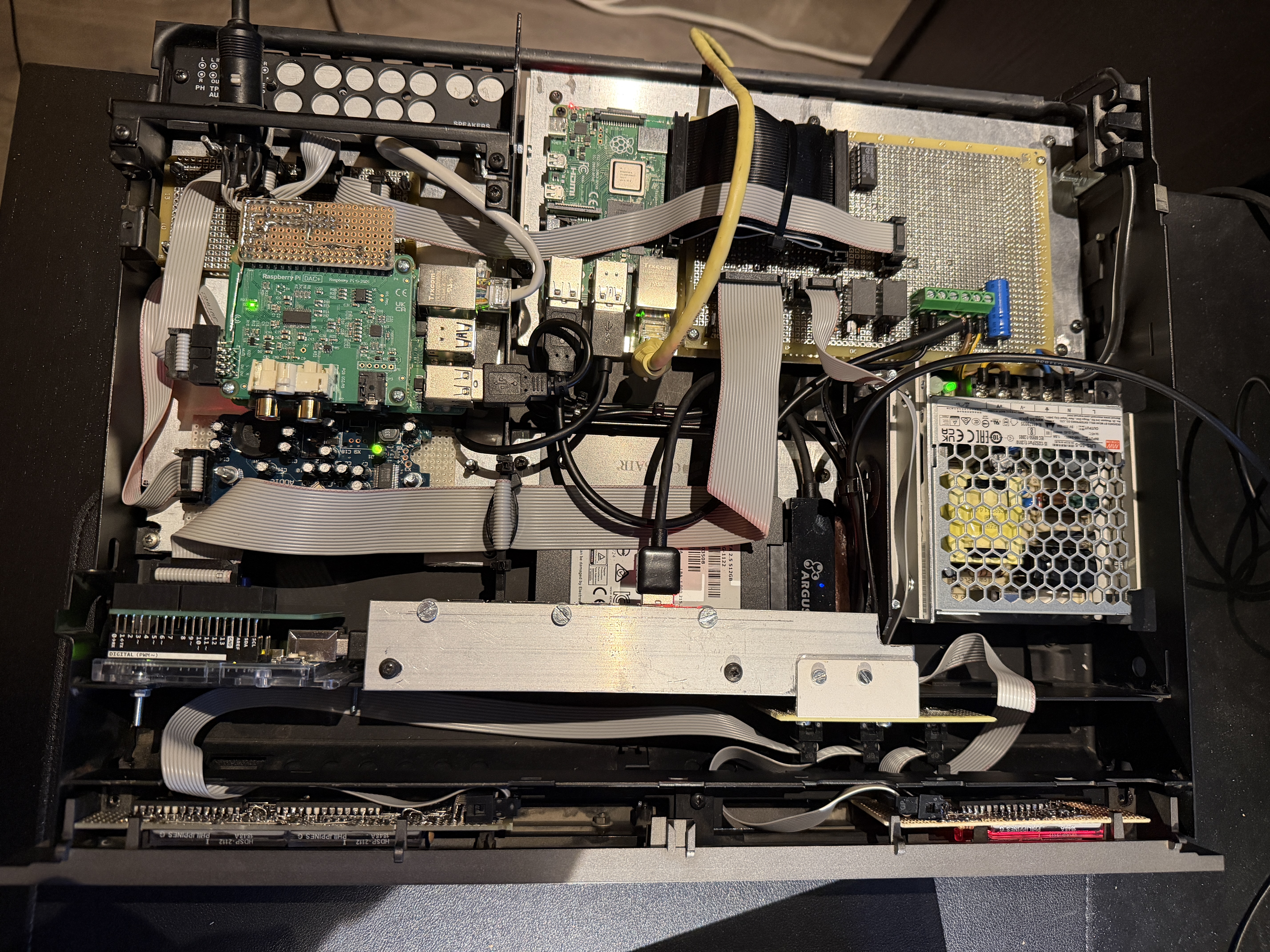
Time for an update.
It’s not only a network player, but it has been upgraded to a network player AND network recorder.
So I am now able to record any signal which comes from the Beomaster to FLAC files on the internal harddisk.
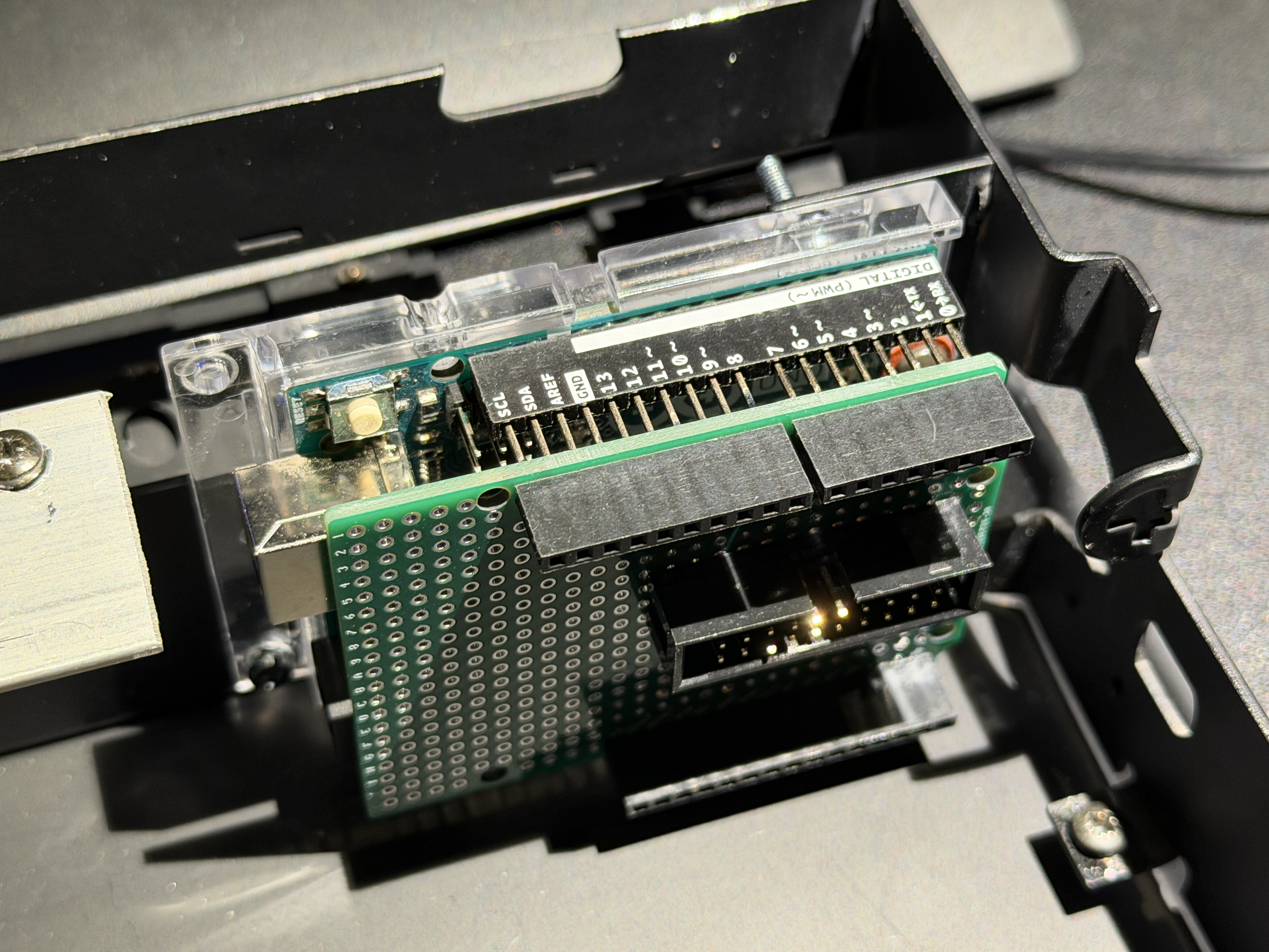
It’s pretty crowdy, but I was able to build in a Behringer UCA-202 USB soundcard. I took all of the unnessecary parts of this soundcard, and mounted it on a standard grid PCB with 10-pin IDC connector.
A Python based script starts the recording to the internal RAM of the Raspberry Pi. After the recording the file is split into multiple tracks when a pause of 2 seconds is detected.
After this, the file(s) are uploaded to Volumio.Maybe a moderator can remove the attachment? This was not inteded, I wanted simply add a picture but did it wrong 🙂
Location: Netherlands
My B&O Icons:
Your VU question triggered me to try. But the choice for using MCP23017 GPIO expanders behind the screens makes this nearly impossible.
That I2C driven solution is simply not fast enough to process the fast screen changes.
I had it sort of working but after 2 seconds the screens stop working.
It would be possible if I redesign the screen PCB’s with a SPI driven solution but this would imply a full redesign of all my PCB’s.
So for now I’ll stick to the curent design without VU metersLocation: Netherlands
My B&O Icons:
So cool! Waiting to see your post about VU meters! 😁
Regards, Johan
Thought about it, but in my usecase it’s not that easy. The Pi which controls the screens doesn’t handle the music streaming.
Location: Netherlands
My B&O Icons:
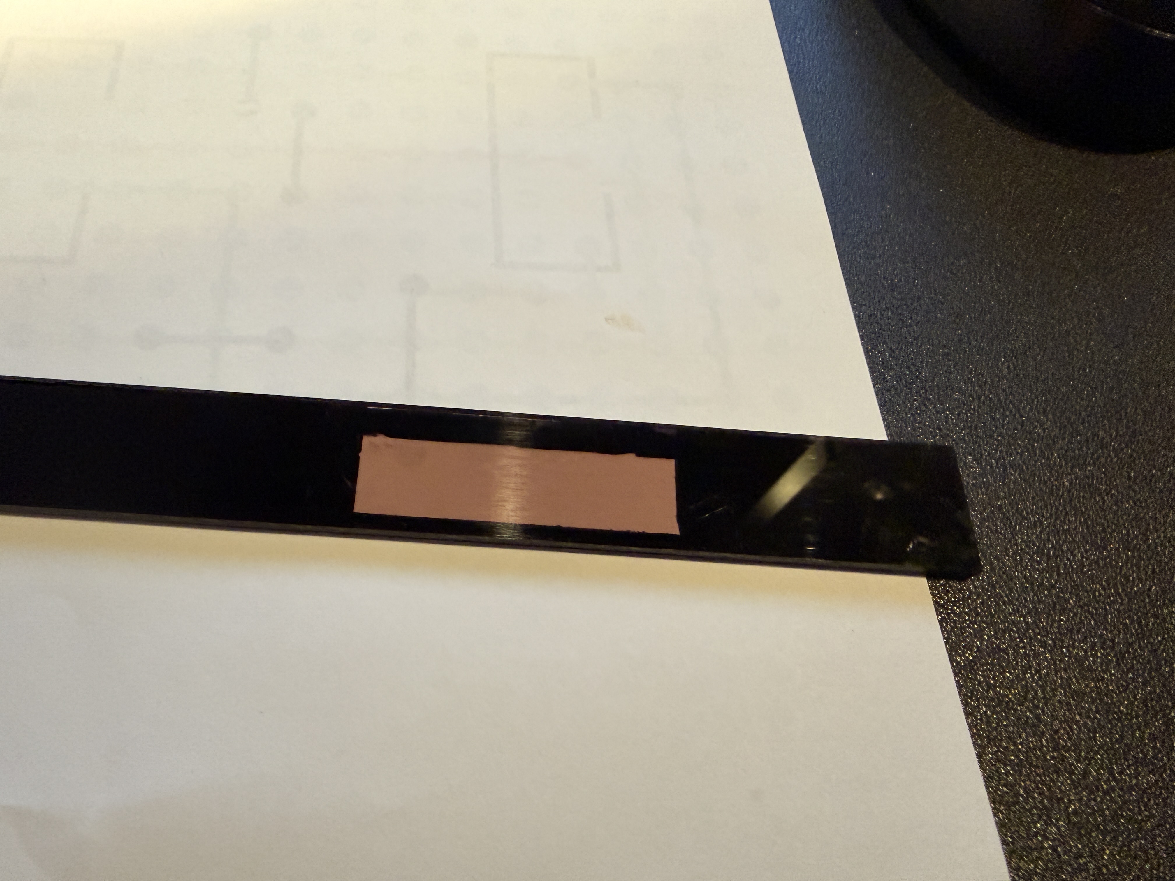
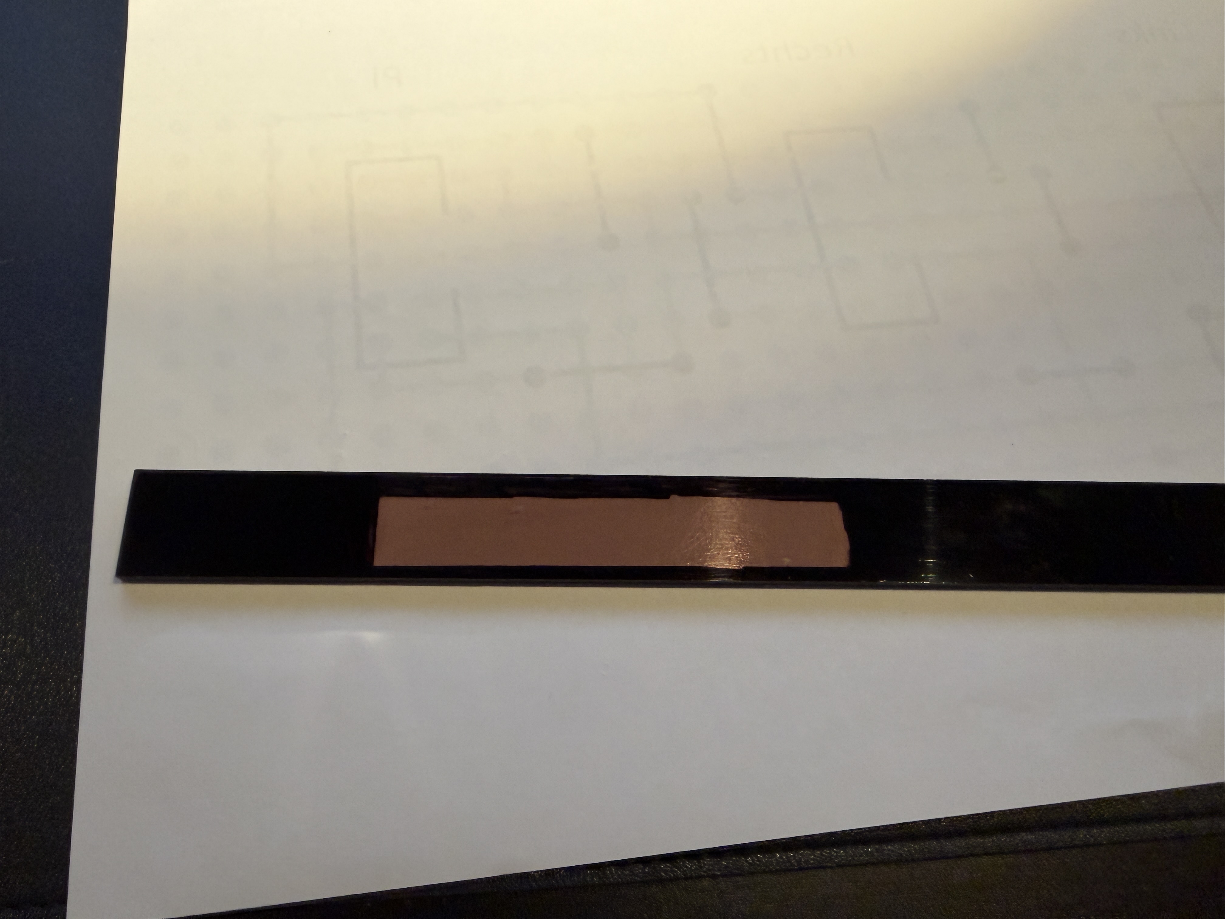
So the coating needs to be removed where the screens reside.I did this with grinding paper and after that if polished the clear plexiglass.
This polishing needs more work, but for now I am happy with it
Other places where the plexiglass is sort of clear need to be masked. I did this simply with a marker pen on the backside of the plexiglass.
Location: Netherlands
My B&O Icons:
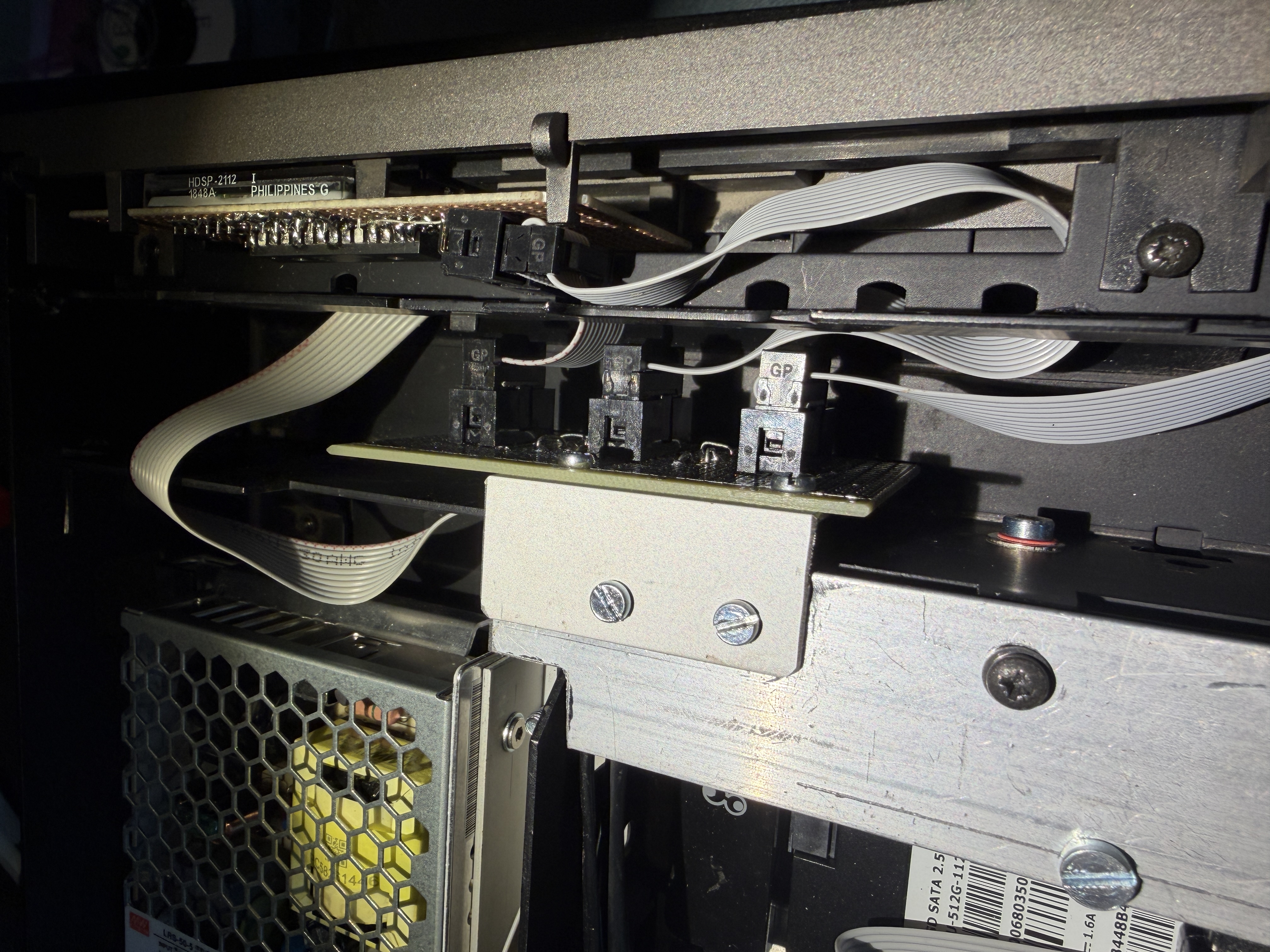
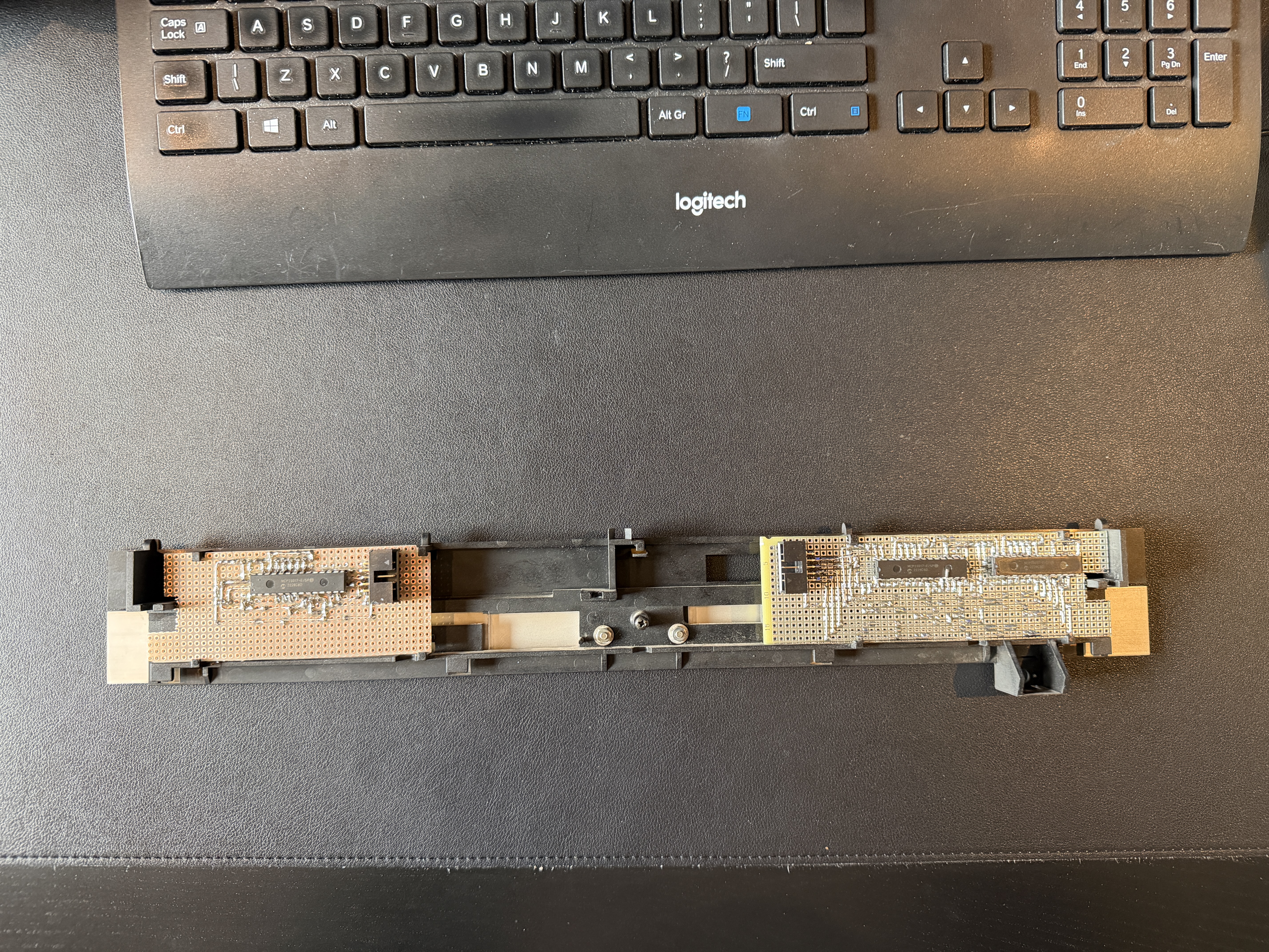
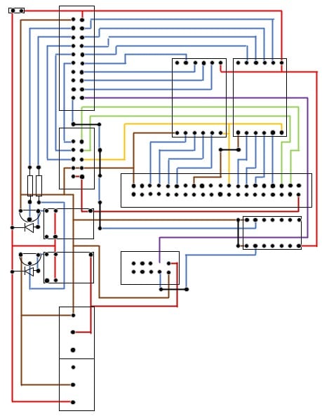
Now that the screens are ready, they need to be connected to the Raspberry Pi.
At the time I built the central connecting PCB, the idea was to create 1 large screen but this was impossible without the “tools”
So I need to connect 2 screen PCB’s to the main PCB, but I anticipated for just 1.
Creating a second socket would imply a complete redesign of the main PCB.
I decided to create an intermediate PCB.
Behind the front panel where normally the CPU of the Beomaster resides I had enough space to position this extra unforseen PCB

Location: Netherlands
My B&O Icons:
 Now the creation of the PCB’s behind the frontpanel. As said, I try not to use barbarian tools like angle grinders.
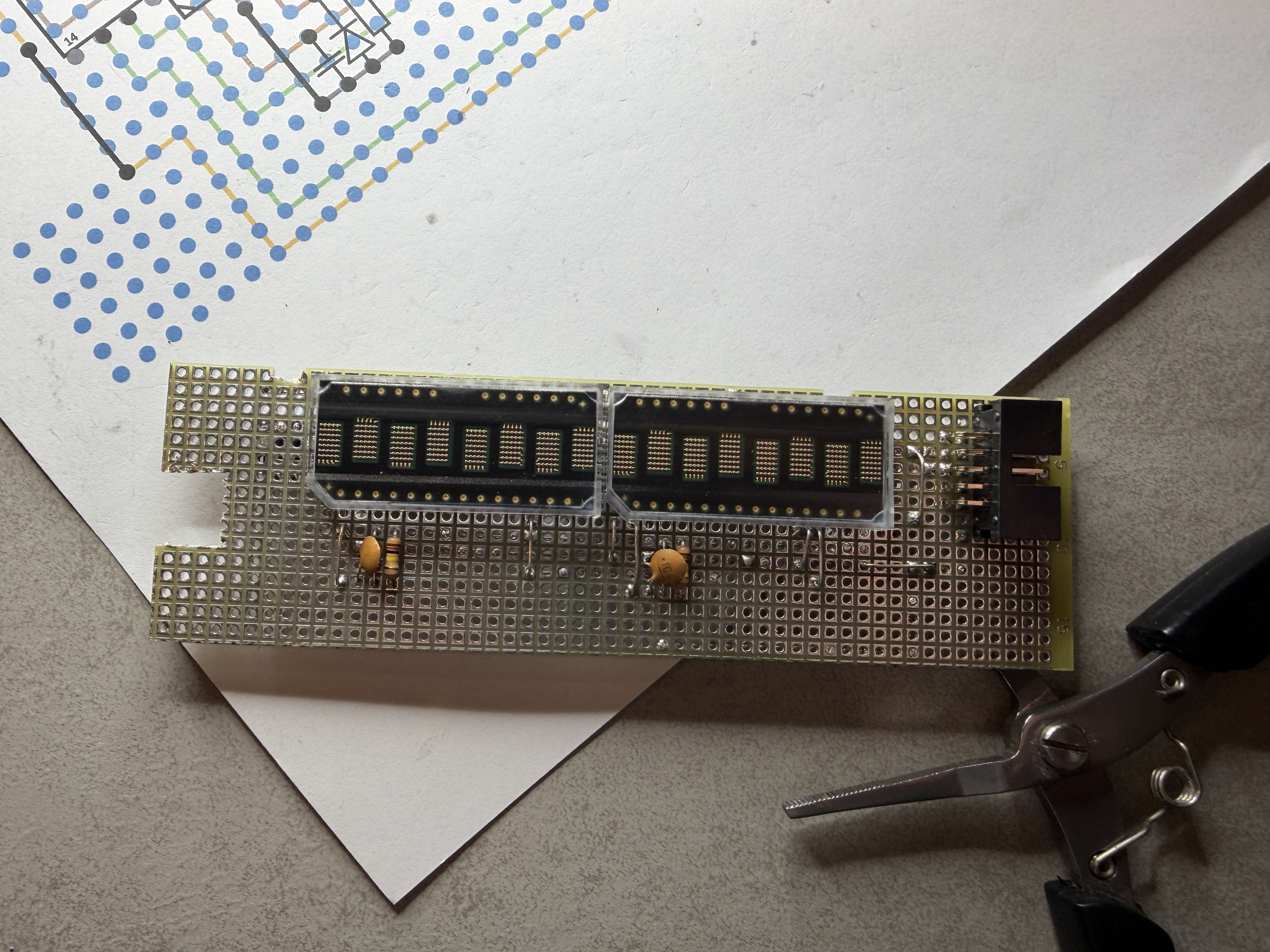
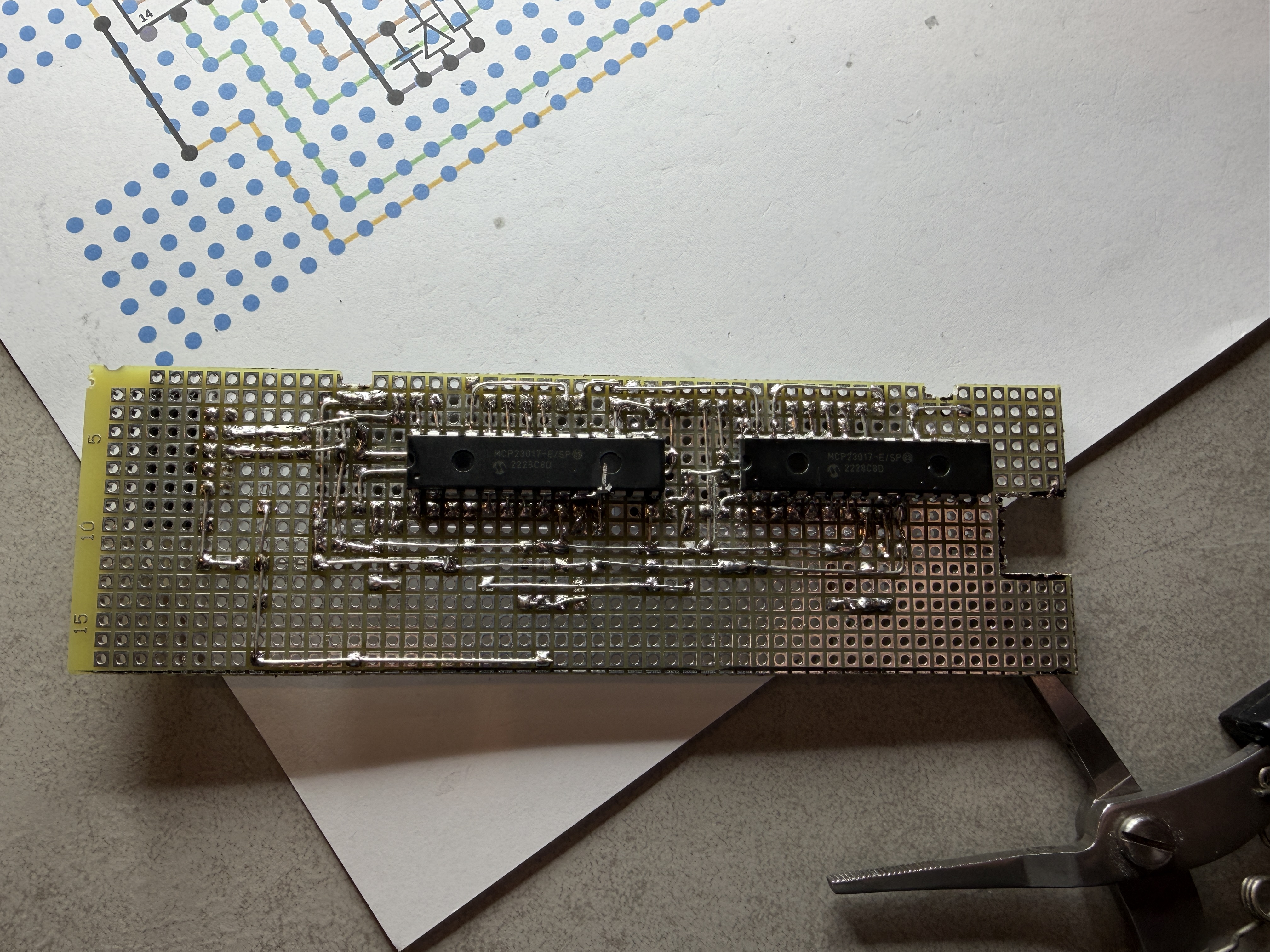
So the goal is to create something which can be placed in the original frame. It’s really tight in there but I managed to create a PCB with the right proportions, 2 screens and 2 gpio expanders.
This PCB will be placed on the left side of the frontpanel. It was a bit of a struggle, while the expanders had to be placed on the backside of the PCB and the screens on the front of the PCB
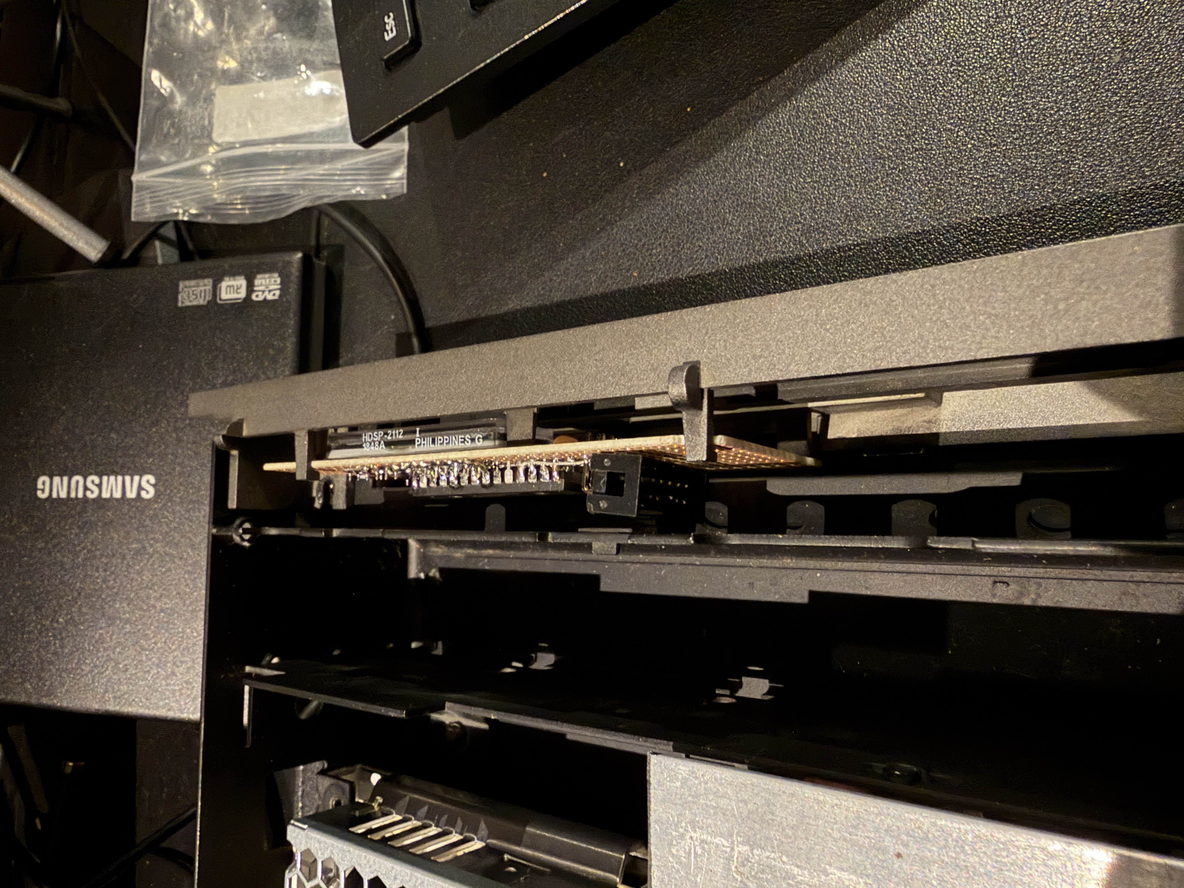
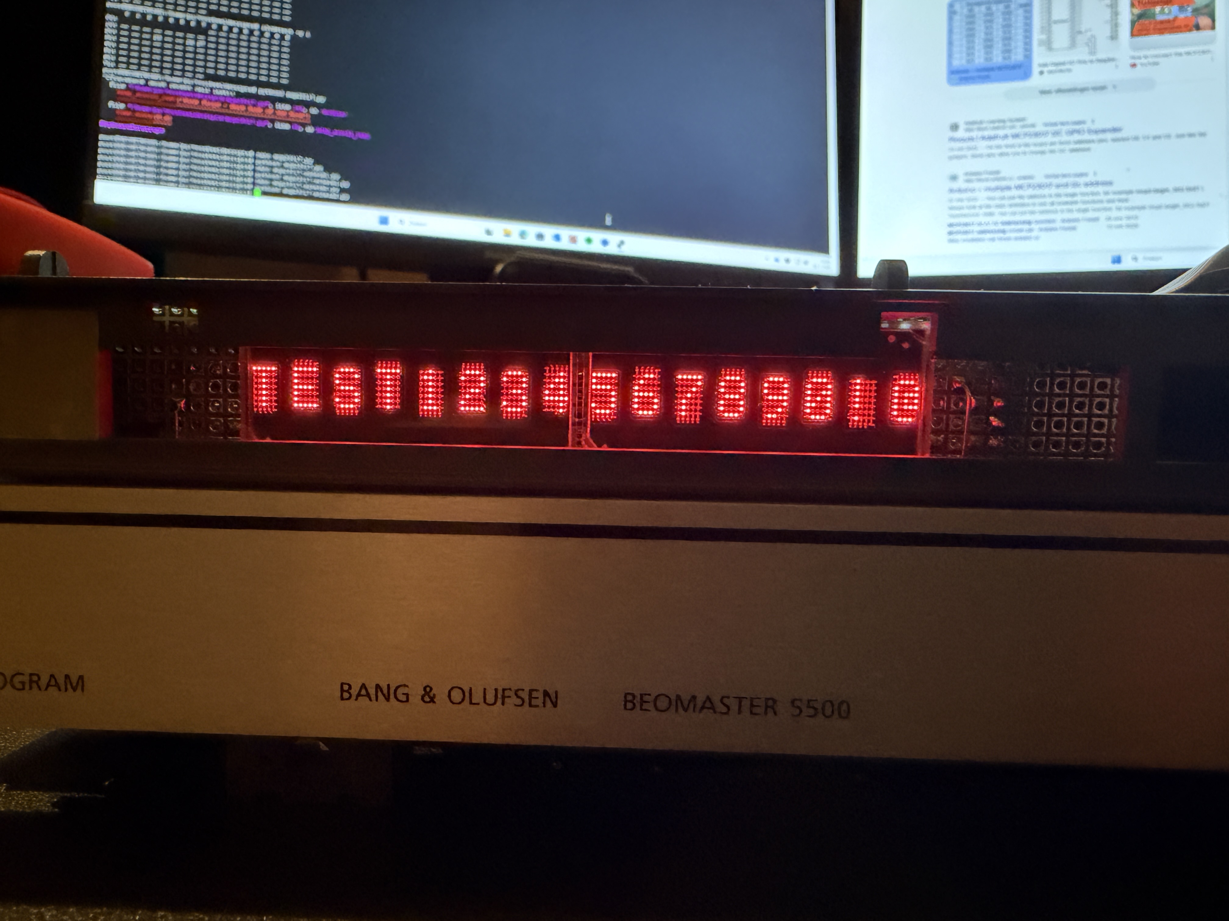
On the right side is 1 screen, which is built the same way.
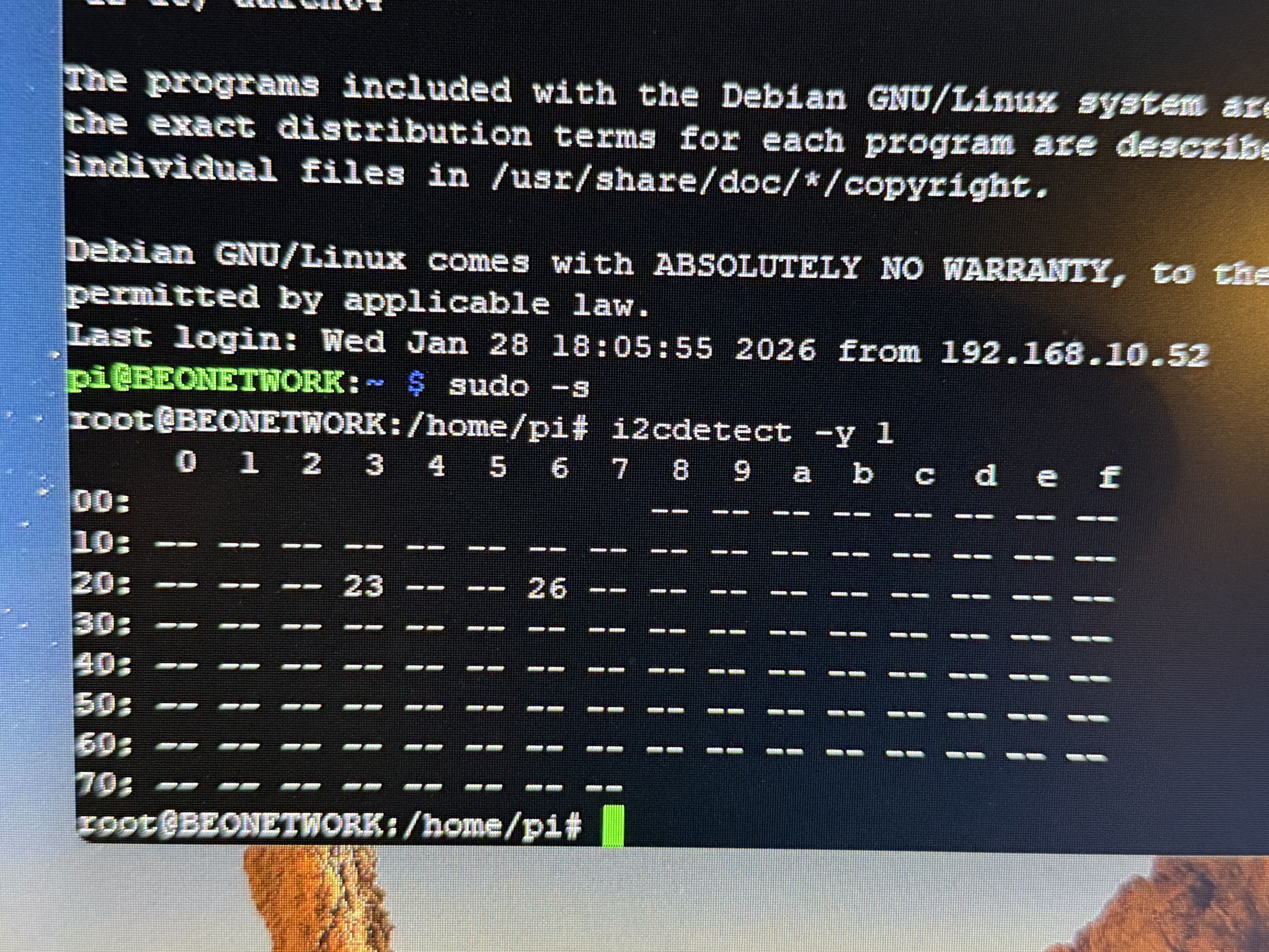
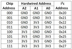
As you can see, it is tight. Very very tight. But it fits A scan on the I2C bus gives me 2 addresses, those are the 2 GPIO expanders on the left PCB.
The right PCB was not connected at that moment. Time for a test .
Location: Netherlands
My B&O Icons:
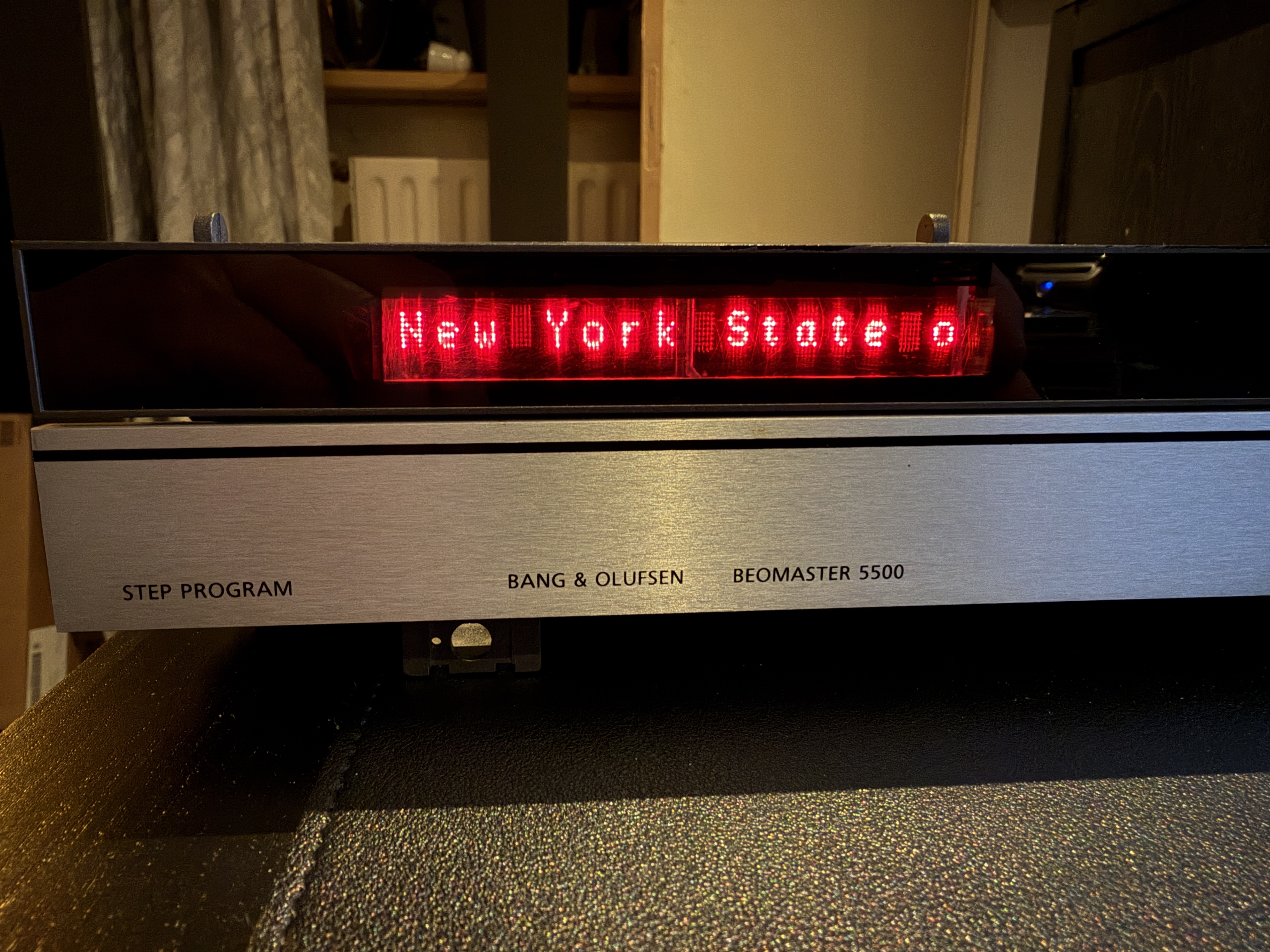
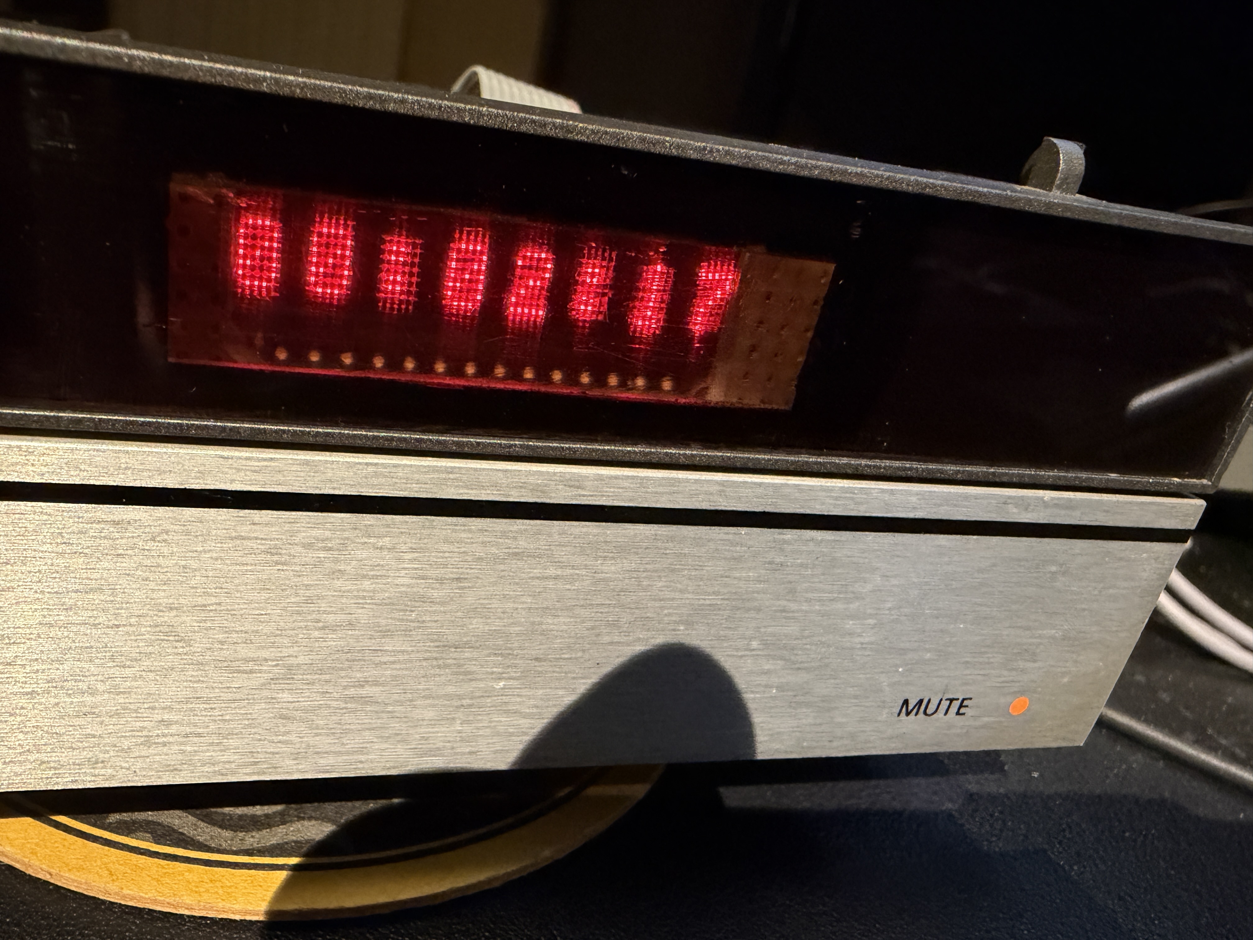
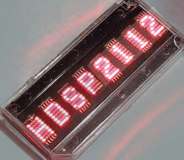
8 characters per screen, the possibility to position more screens next to each other and controllable with gpio pins on the Raspberry Pi. I found a really nice website with all info I needed to control the display(s) with Python.
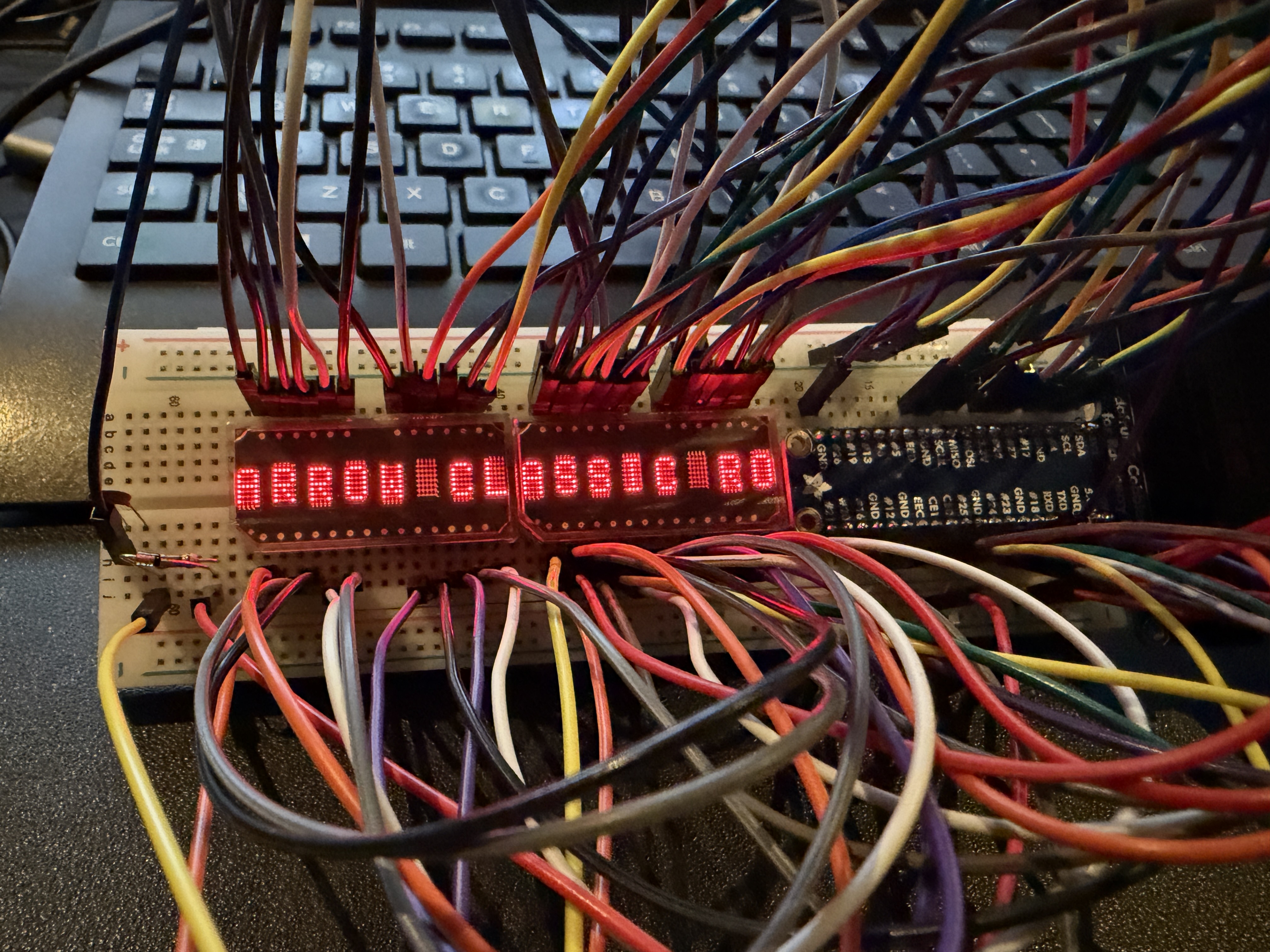
LED display HDSP-211x | Arno Welzel A little bit of experimenting gave me pretty soon a nice flashing disco.
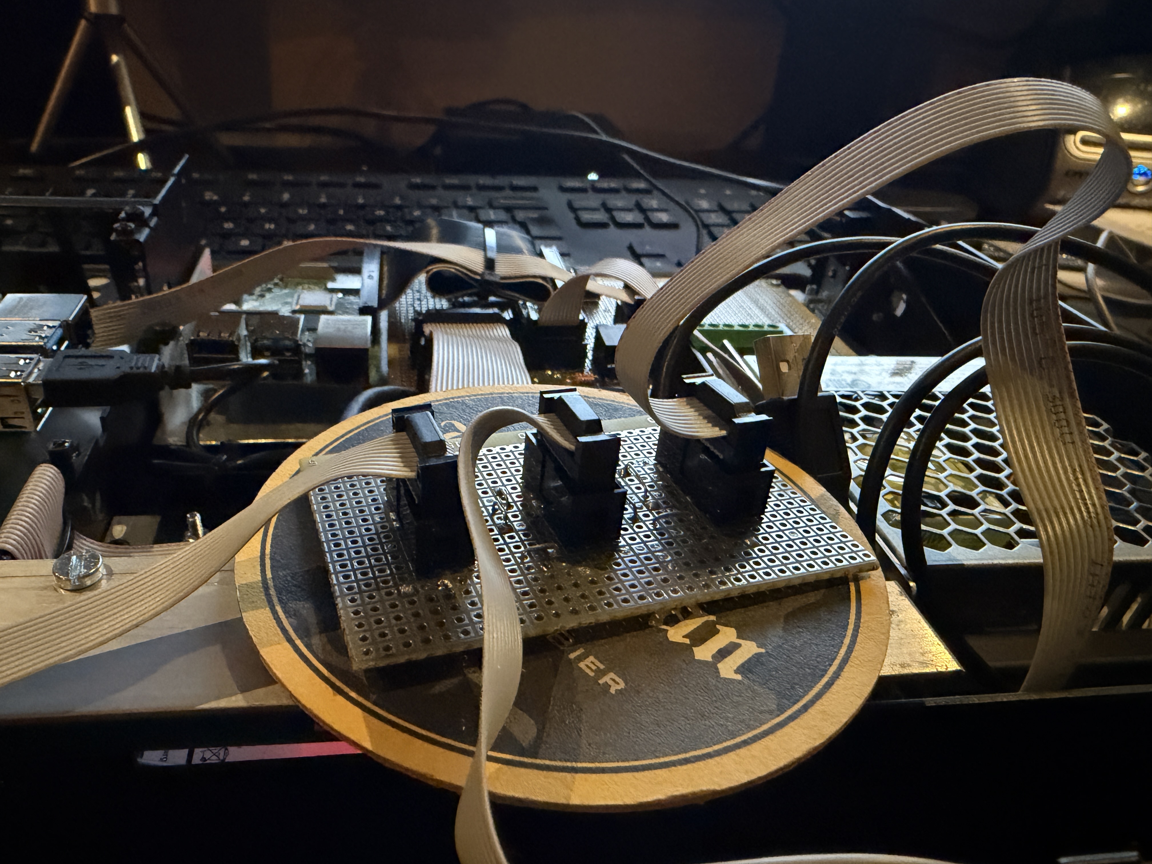
As you can see there a a LOT of wires. This was a bit of a headache. This would mean a huge flatcable to the frontpanel.
Also, because of the 6 gpio pins from the Pi to the Arduino there were not enough GPIO ports left on the Pi to control 3 screens which I had in mind.
It would be nice if I could control the screens with some sort of display controller which is small enough to be situated behind the frontpanel.
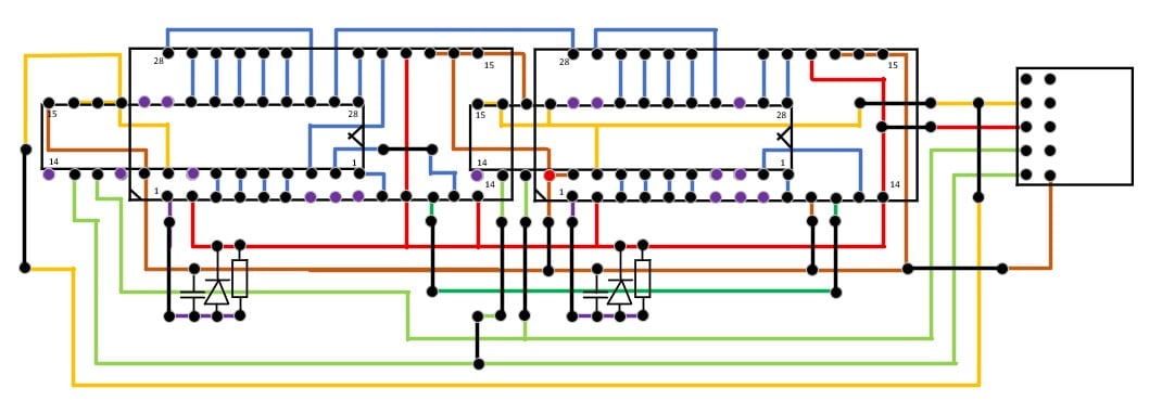
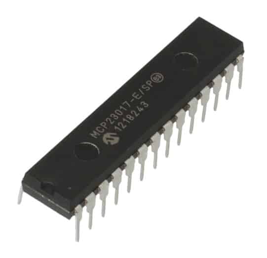
My solution: A MCP23017 GPIO expander.
This fellow is a I2C bus driven GPIO expander. When connected you get 16 extra GPIO ports per IC.I2C bus control is 2 wires (clock/data), and some wires for power supply of the IC and screens.Also, you can control different expanders on the same bus by addressing them different.
I decided to give each of the matrix screens their own GPIO expander. This way I am able to control them independent, but also be able to cascade it to show longer text.Location: Netherlands
My B&O Icons:
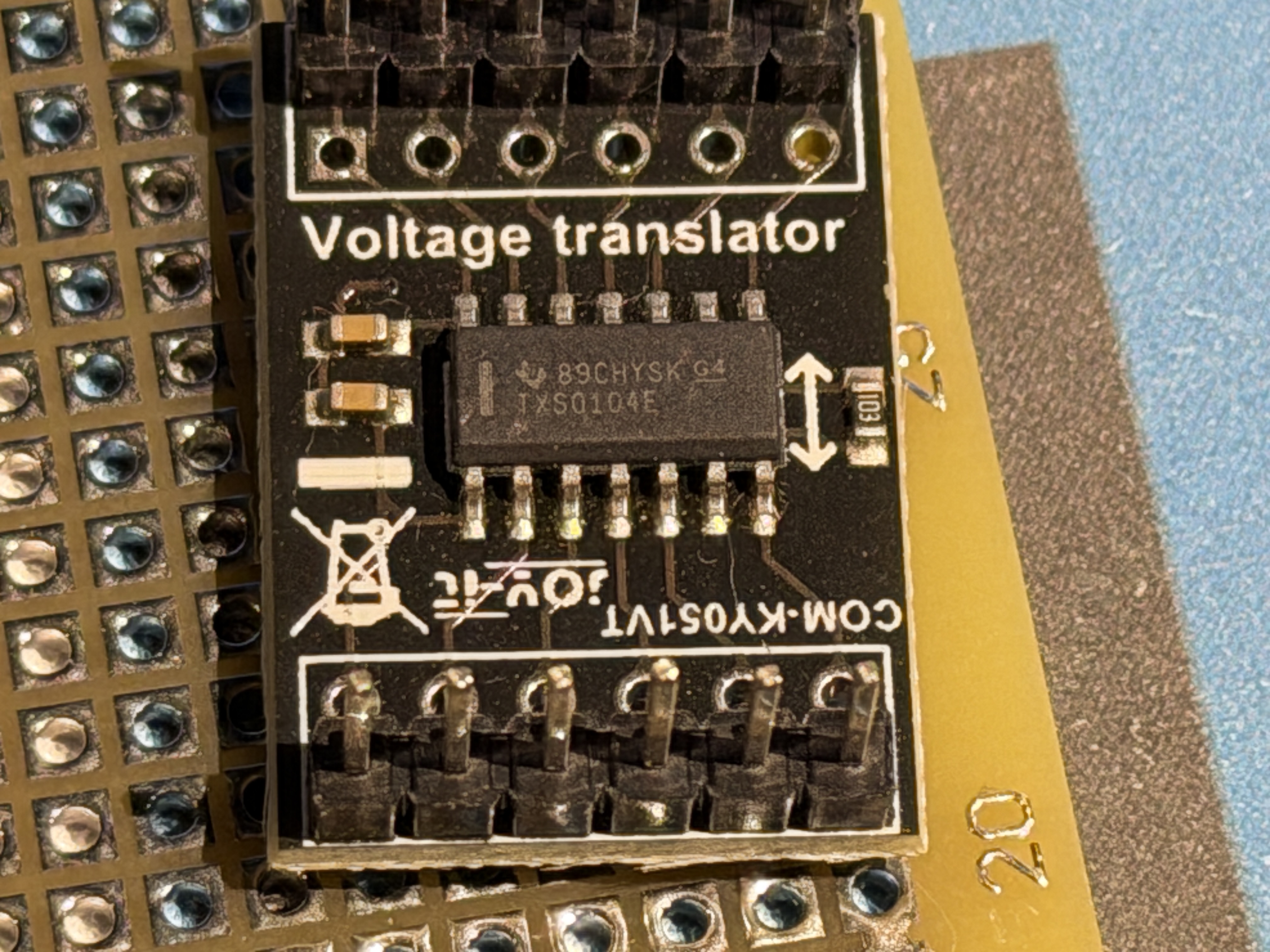
About the voltage translators.
I took 2 KY-051 translators for the communication between the Raspberry Pi and the Arduino.
It was my intention to talk over I2C, but for some reason I didn’t get it to work.
So I made a simple solution with 5 GPIO pins. Simple set a binary code on those 5 pins, and use a 6th pin as ACT pin.
As soon as the code is on the pins, toggle the ACT pin and the Python script on the Pi takes reads the binary code.with 5 bits I can send 32 different codes. That should be enough for my usecase
I’m more a hardware guy than a software guy. So maybe there are much more simple solutions, this is what I got working.Location: Netherlands
My B&O Icons:
For sure, if we can help each other I’ll be happy to collaborate wich each other.
For now I work with the BL80 standard, and only need to listen to the commands.
So my usecase is pretty straight forward.
But maybe if this all is ready I can try to talk to the Beomaster for showing text on the Beolink 7000 with BL86 protocol.Edit: I did a search on your topics, pretty impressive what you already achieved!
From protocol/software perspective you’re way ahead of meLocation: Netherlands
My B&O Icons:
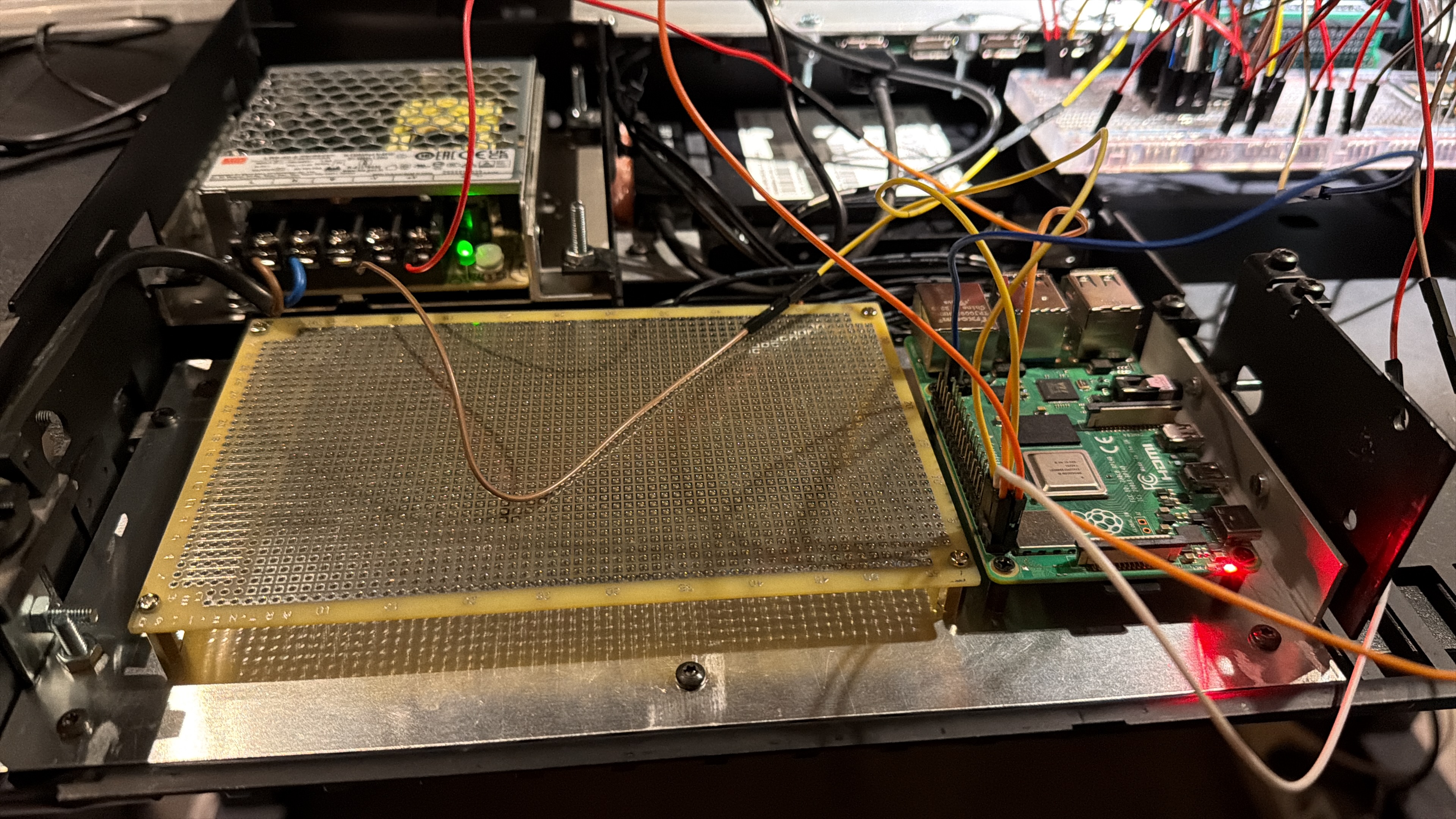
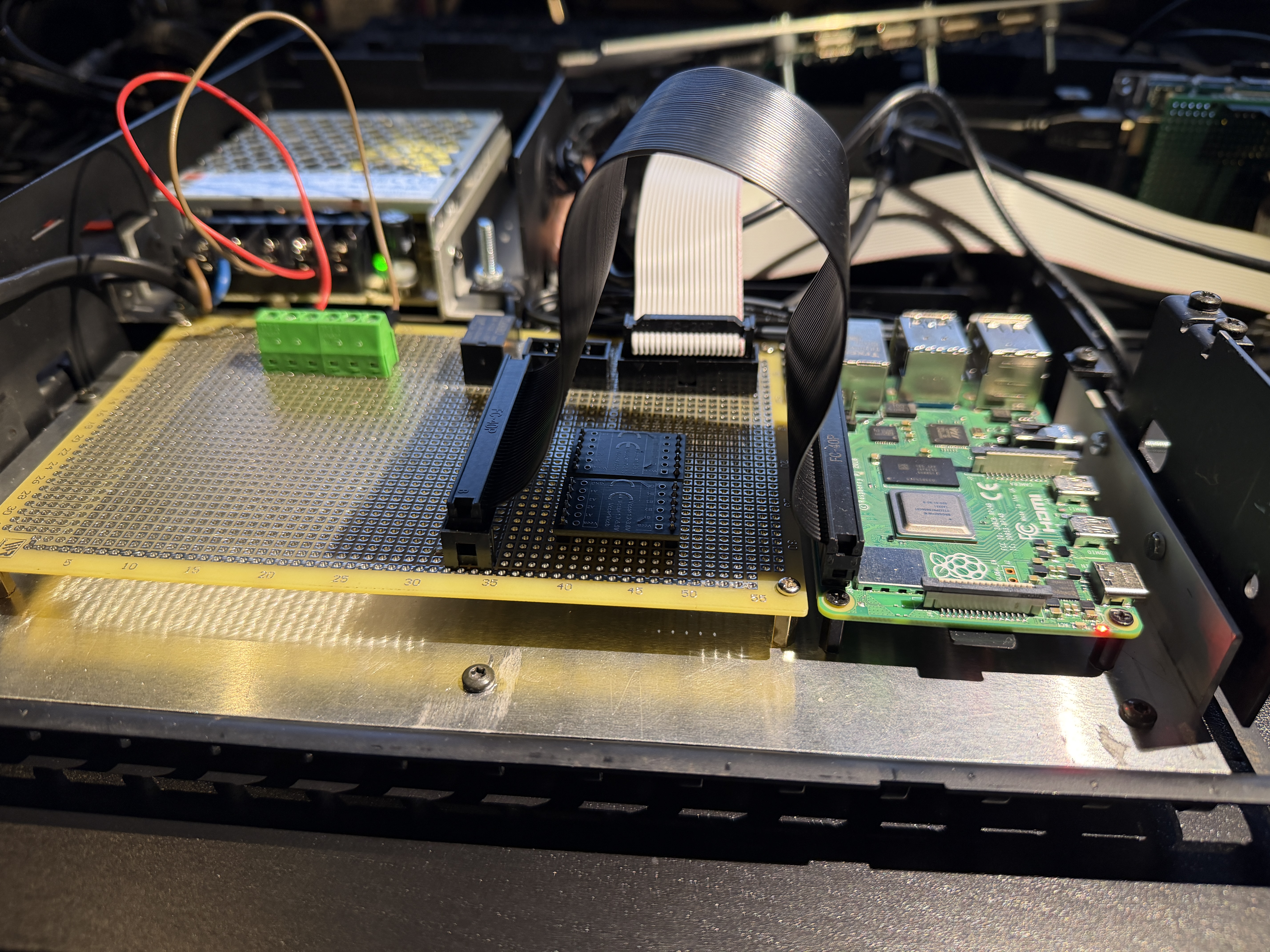
This baseplate is also mounted on the internal frame, and is not connected to the bottom plate of the Beomaster housing.
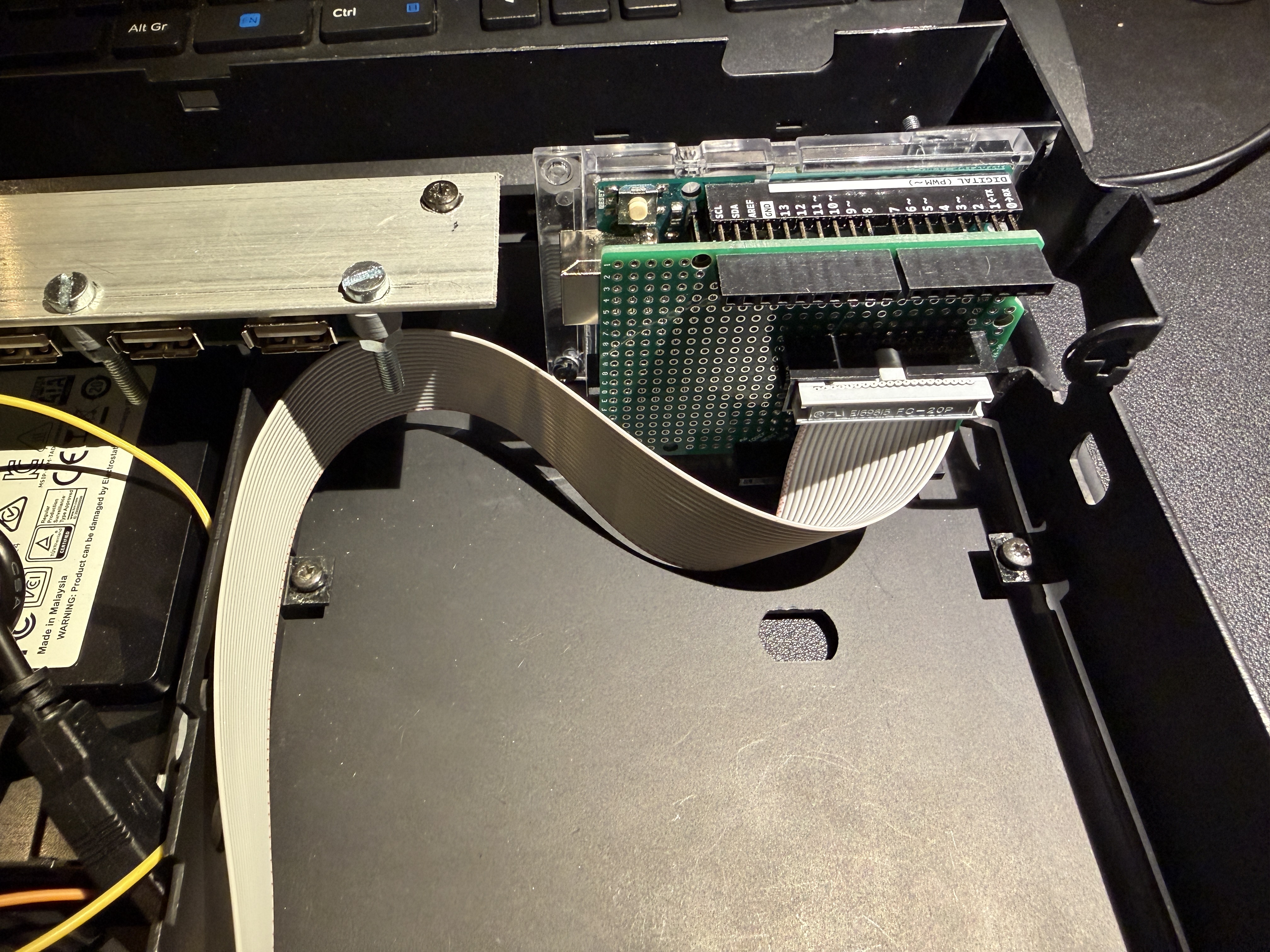
The universal grid PCB will be the central PCB, to which all components will connect (ideally by a flatcable)
In the background already a sneak preview of the testing of LED Matrix displays from the Raspberry Pi.
The Raspberry Pi on the picture is not the Pi which will be the Volumio streamer, but this Pi will control the LED displays and talk to Volumio with API calls.
Via this API calls we get the currect state of the streamer to project on the displays, but also sends commands to Volumio like start/stop/next etcetera.
Designing the print layout takes a lot of time but I was able to position all parts on a small layout. This gives me room for future expansion.
 The first components are mounted on the print. A 40 pin IDC connector to the Raspberry Pi, a 20 pin IDC connector to the Arduino
The power supply is connected to the PCB and the first relay is situated.
Underneath the 40 pin flatcable you see 2 small PCB’s. Those are voltage translators.
This is because the Arduino has a 5 volt GPIO voltage, and Raspberry Pi operates on 3,3 volt level.
More to follow, for today this is it.Location: Netherlands
My B&O Icons:
Also, I don’t want hundreds of single wires from one to another component.
Ideally there should be one connector with a flatcable on each part, and some sort of connecting board where all comes together.
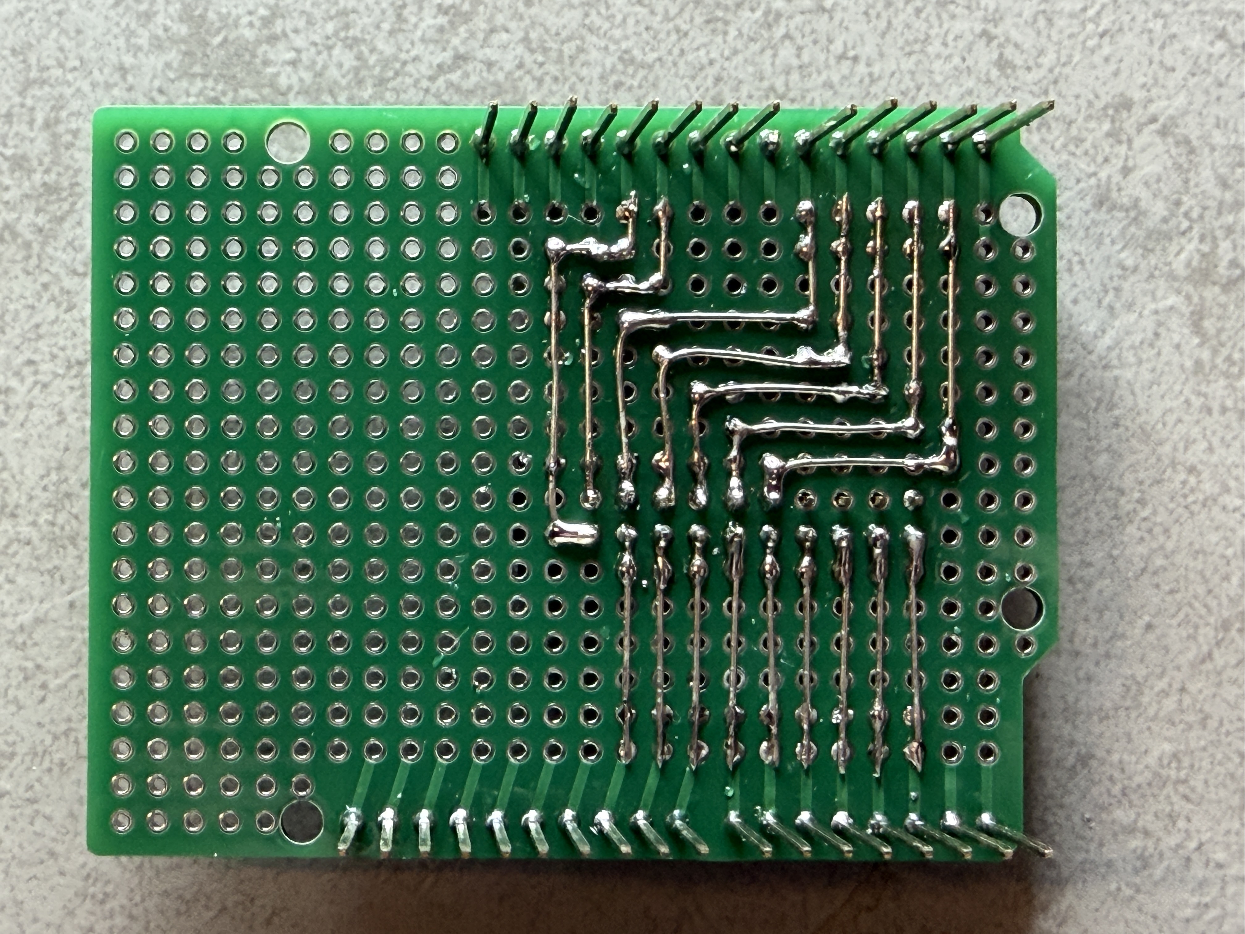
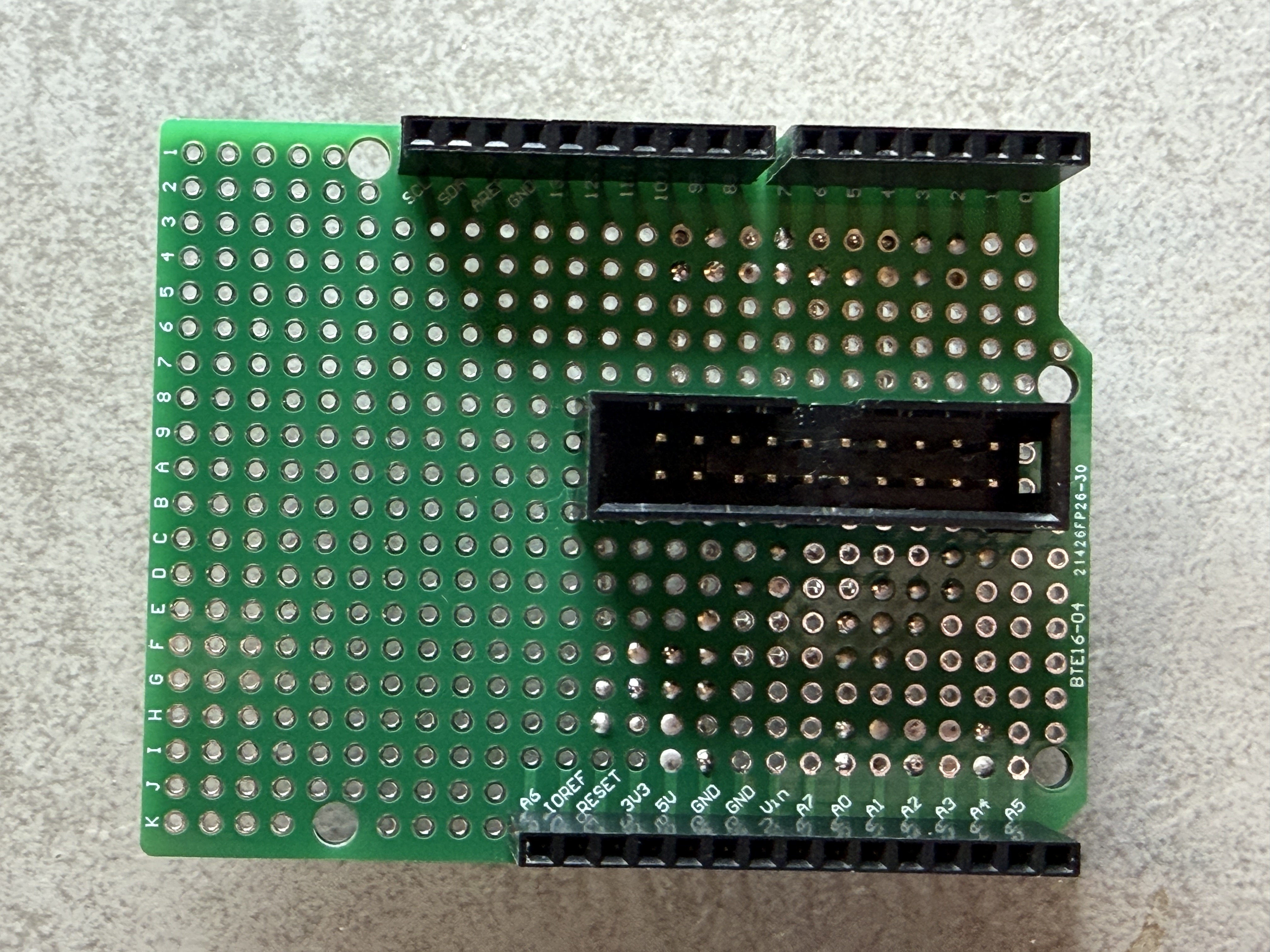
This meant I had to create a breakout board for the Arduino. I found a nice board on Amazon which could help me with this.
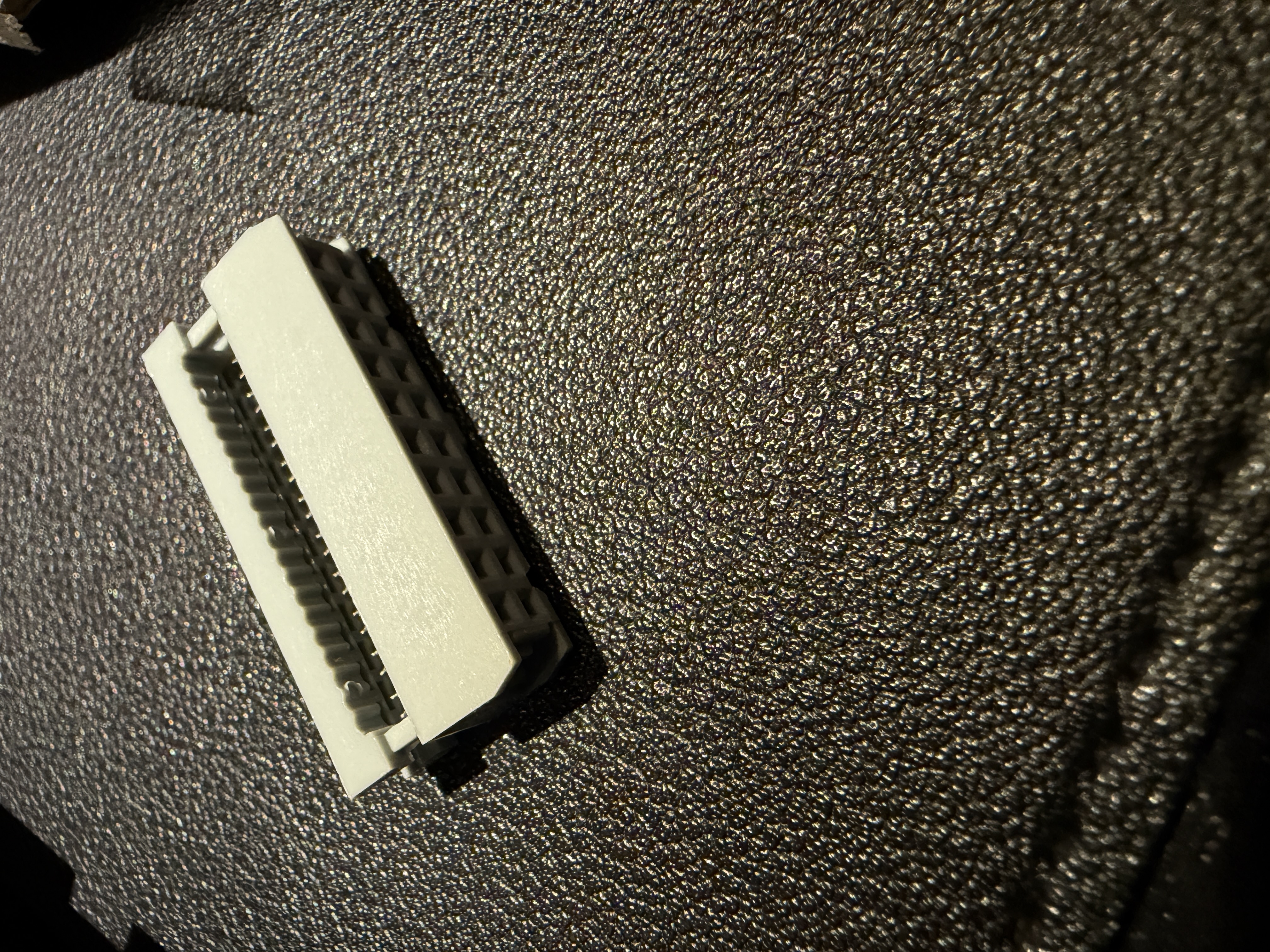
Combined with a 10 pin IDC connector it ticked all the requirement boxes.
Power can also be applied via this connector, so the huge power plug which normally supplies the voltage to a Arduino could be omitted.
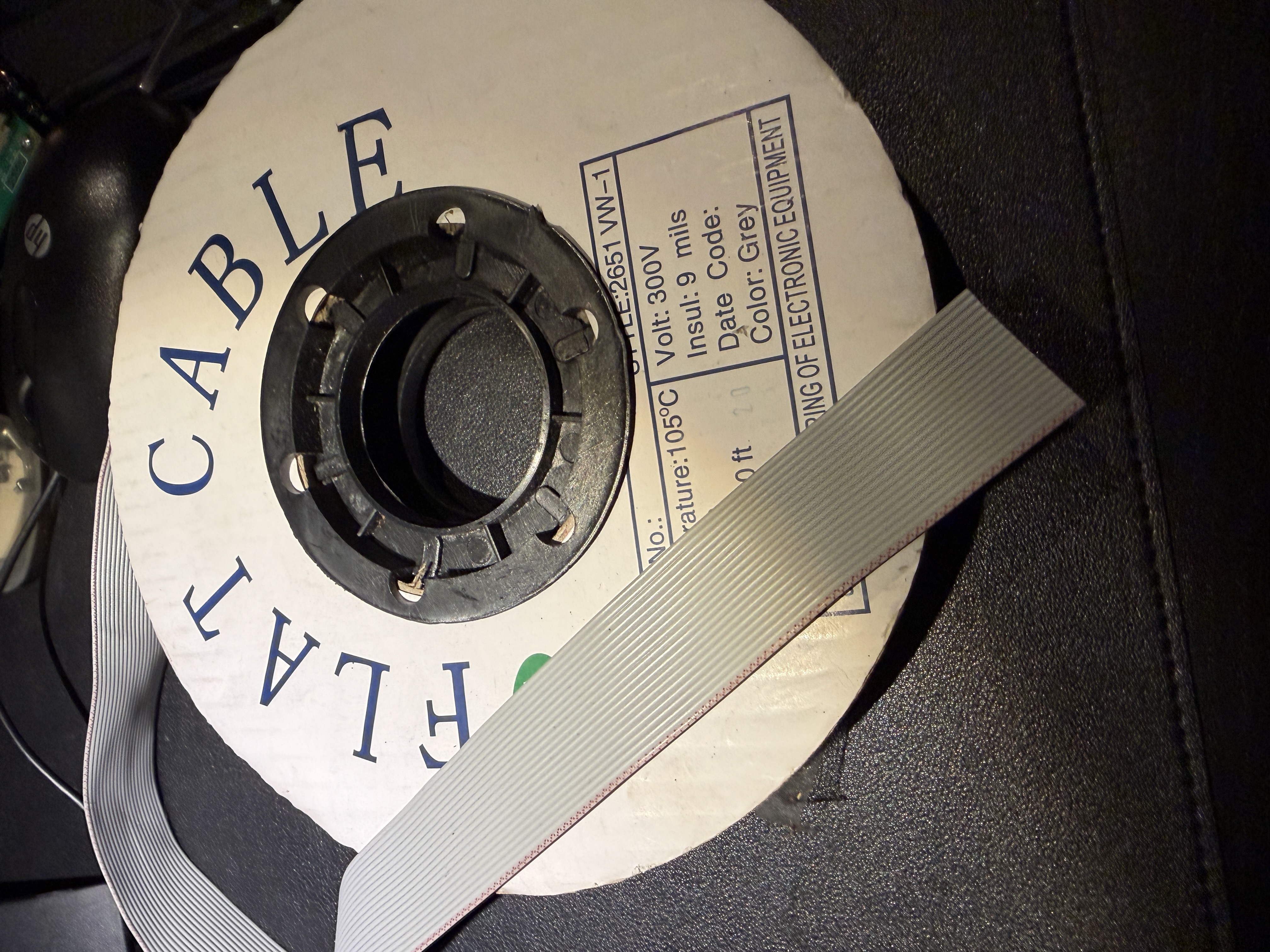
Flatcable and connectors were ordered so I could make my own cables at the disired length.
Location: Netherlands
My B&O Icons:
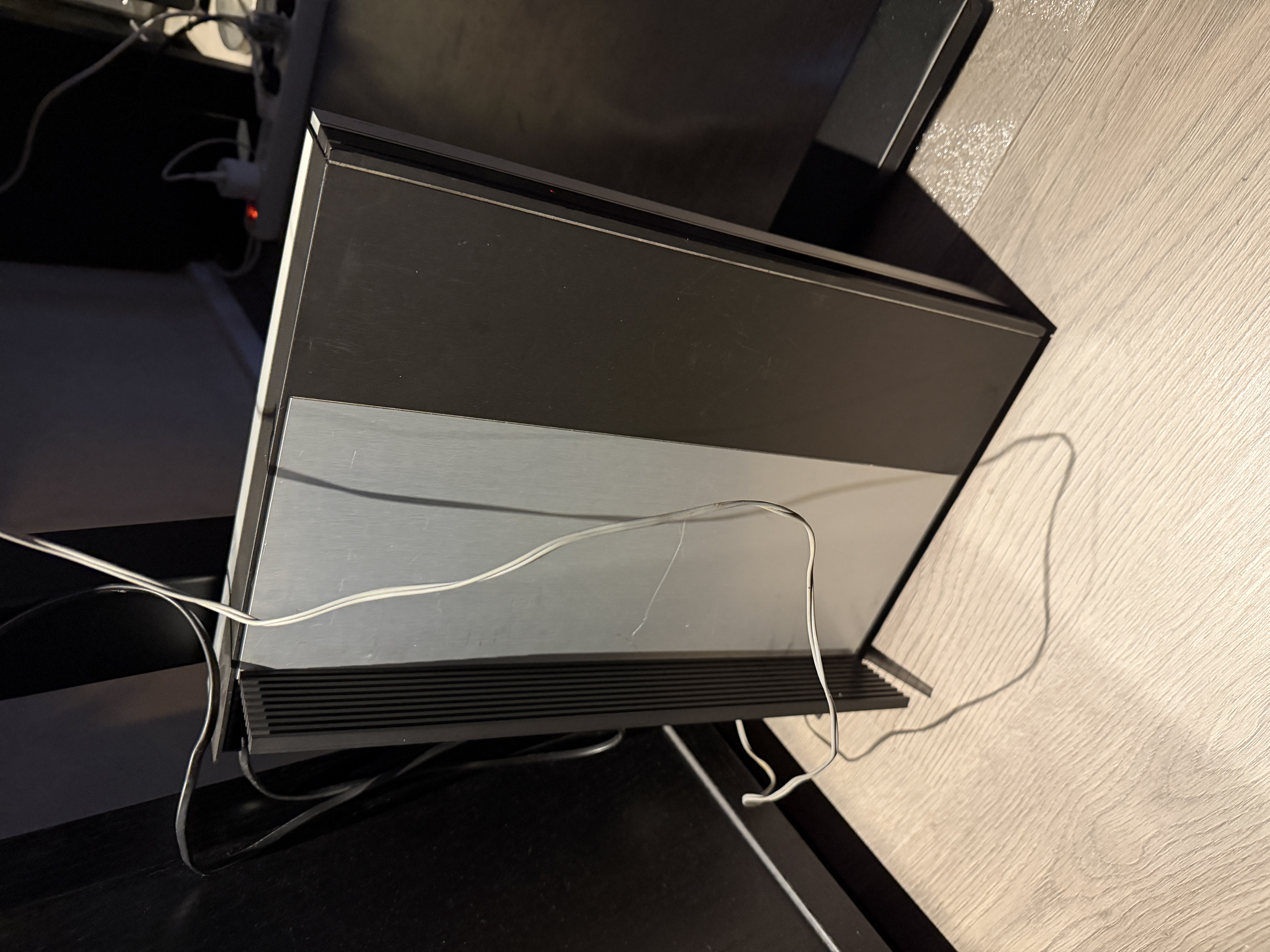
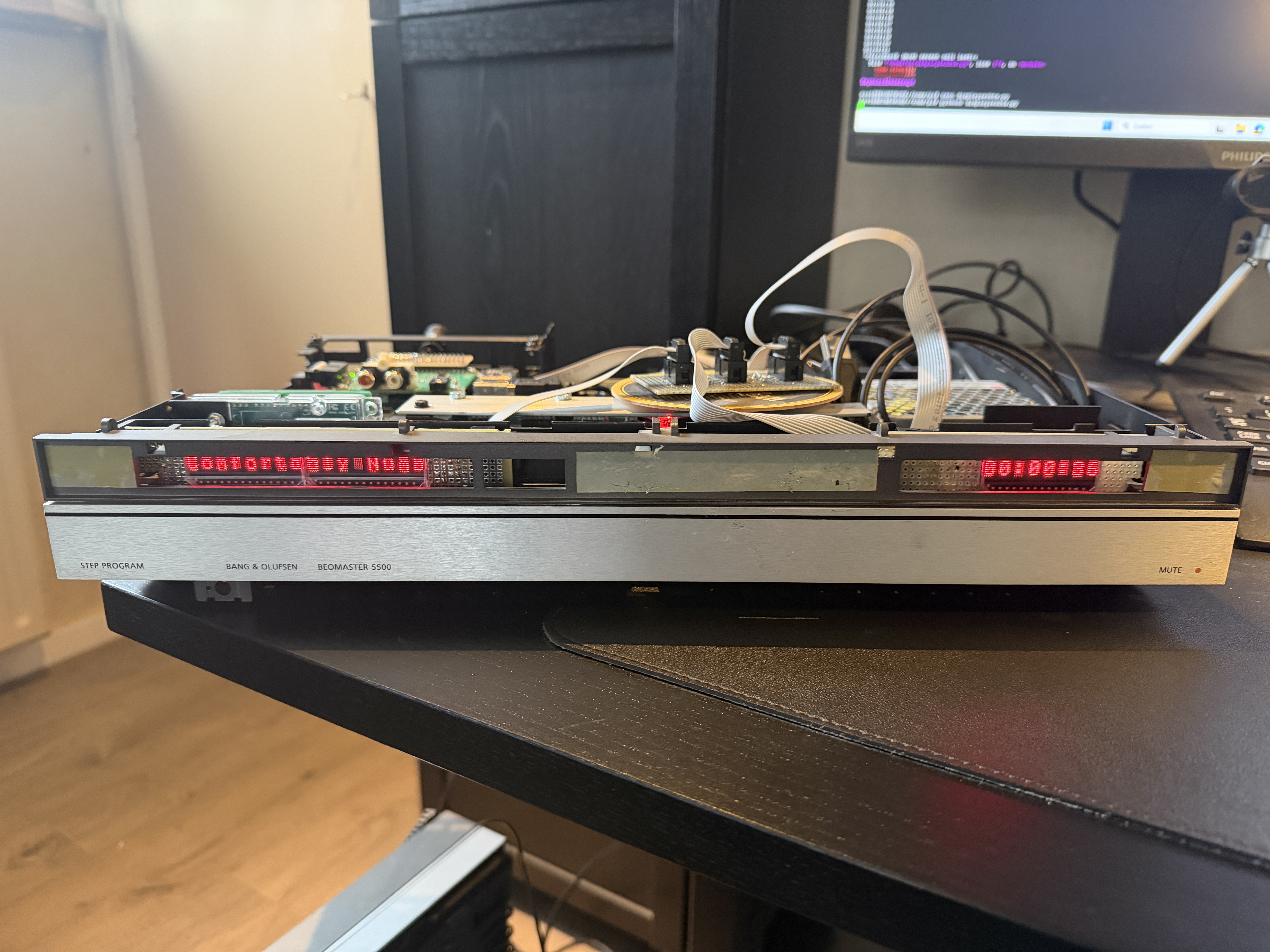
Now we need a housing which gives the look and feel of a real B&O device.
There was another Beomaster 5500 lying around in the most appaling state you can imagine.
Full of scratches, all working internal components were transplanted into other 5500’s to give them a new life.
All defect parts were put into this little old scratchy fellow. Time to take his internals of and use the housing for something nice.
Another requirement I didn’t mention before: Try to use the original frame and mounting points.
No drilling in the bottom plate, all components have to be mounted on the internal framing.
Drilling a hole is not a problem, but no angle grinders or other barbarian tools please.
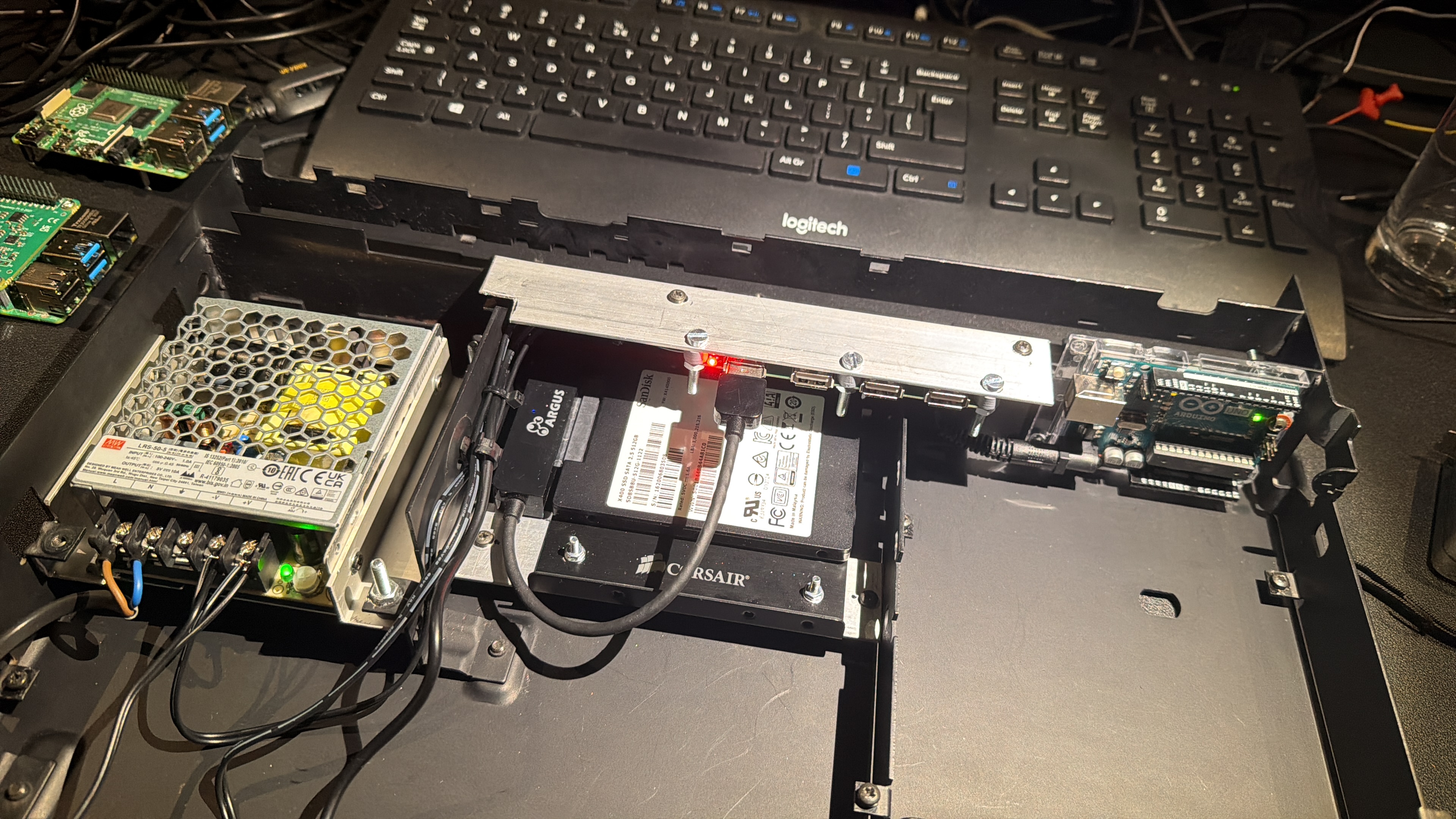
In the left corner on the photo where normally the transformer is situated, I placed a switching 5V/10A power supply.
In the middle where normally the cooling fan is situated, I placed a mounting bracket for a SSD harddisk.
On this mounting plate I put u 500GB SSD disk with a USB to SATA interface.
Above the harddisk I mounted a 5V powered USB hub. This is because I want to connect both a hardisk, but also want to be able to connect an external USB CD drive for CD ripping.
In the right corner is the Arduino situated for the low level controlling of the system.Location: Netherlands
My B&O Icons:
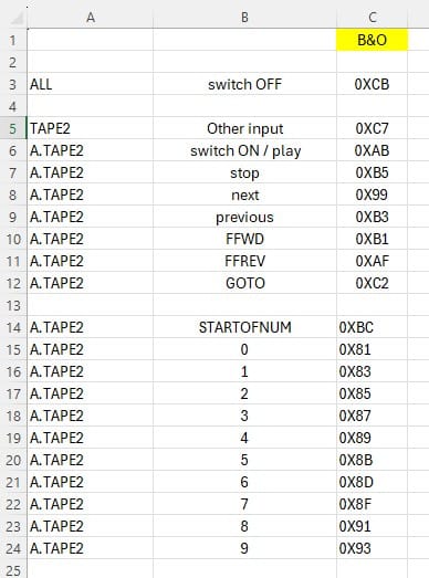
After a lot of testing with the remote control, the codes were making sense to me so I created a little sheet with the commands I am interested in.
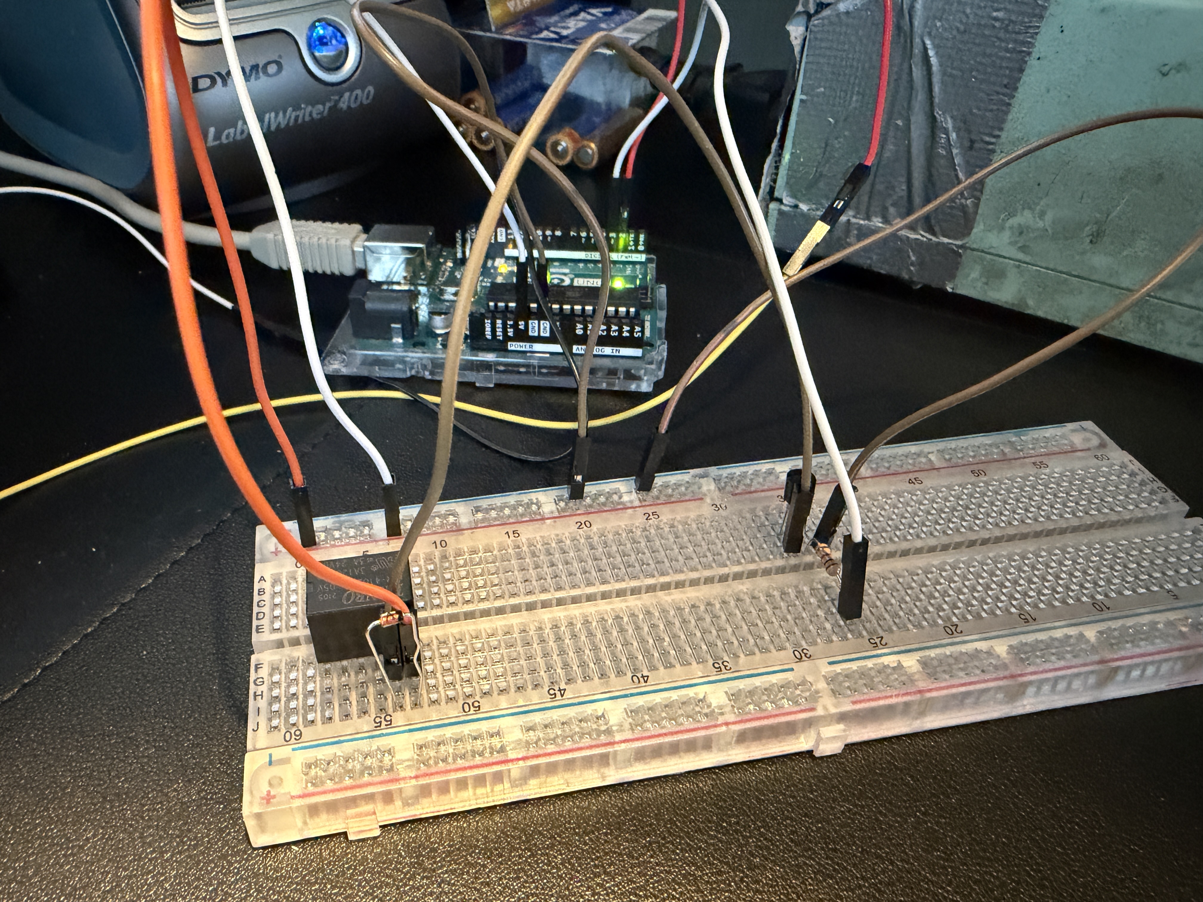
 Now that I understand what the codes mean, I can try to do something with the received commands from the Beomaster.Let’s try to switch a relay as soon as we get code 0xAB.
I need it to power on the Raspberry Pi with the Volumio streamer when we switch the input to Tape 2 on the Beomaster.
Wow, it works! I can toggle a relay by pressing Tape2 on the remote control!
This gives me the guts to proceed with the project.Location: Netherlands
My B&O Icons:
First things first. How to listen to a Beomaster datalink? I didn’t have a clue.
But happily you are rarely the first one to try and find something out.
So a search on the internet pointed me to a project on Github.
GitHub – toresbe/datalink: B&O datalink reverse engineering effortThis project analyses the Datalink port with an Arduino. Just what I needed.
A microcontroller which can control the system on the lowest level, and listen to the commands from “the boss”
In my case I use the BL80 analyzer as starting point.
A tape device on this ecosystem talks with the older BL80 standard, an AUX device talks over the more advanced BL86 standard.
I want the Beomaster to think the device is a “Tape 2” device. So I can use the more basic BL80 standard.
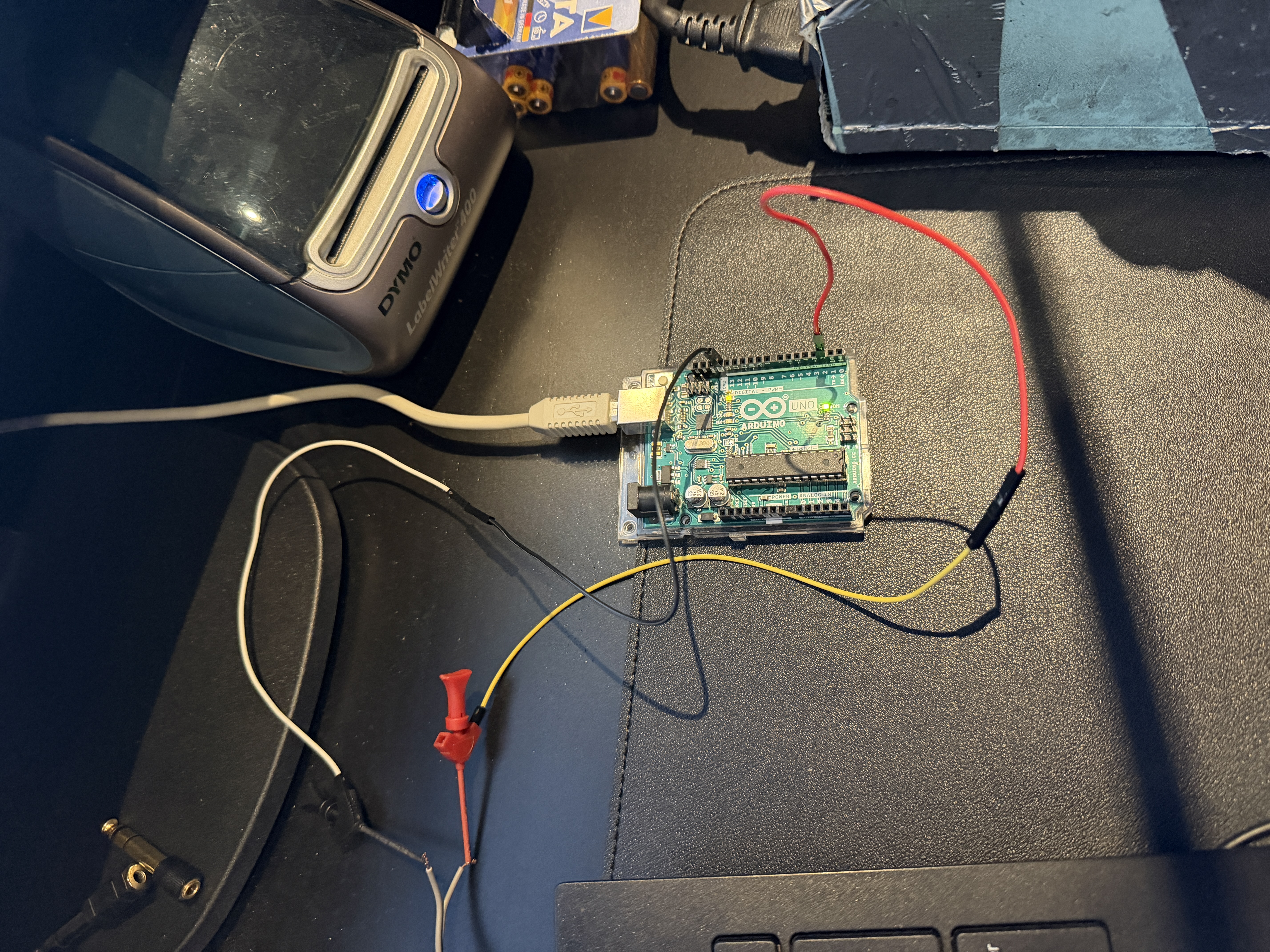
Let’s try. My good old Beomaster 5500 which I use for tests like this will be the test candidate.
A 7 pin DIN connnector with 2 wires soldered on pin 2 -> ground and pin 7 -> datalink which will be connected to the Arduino.

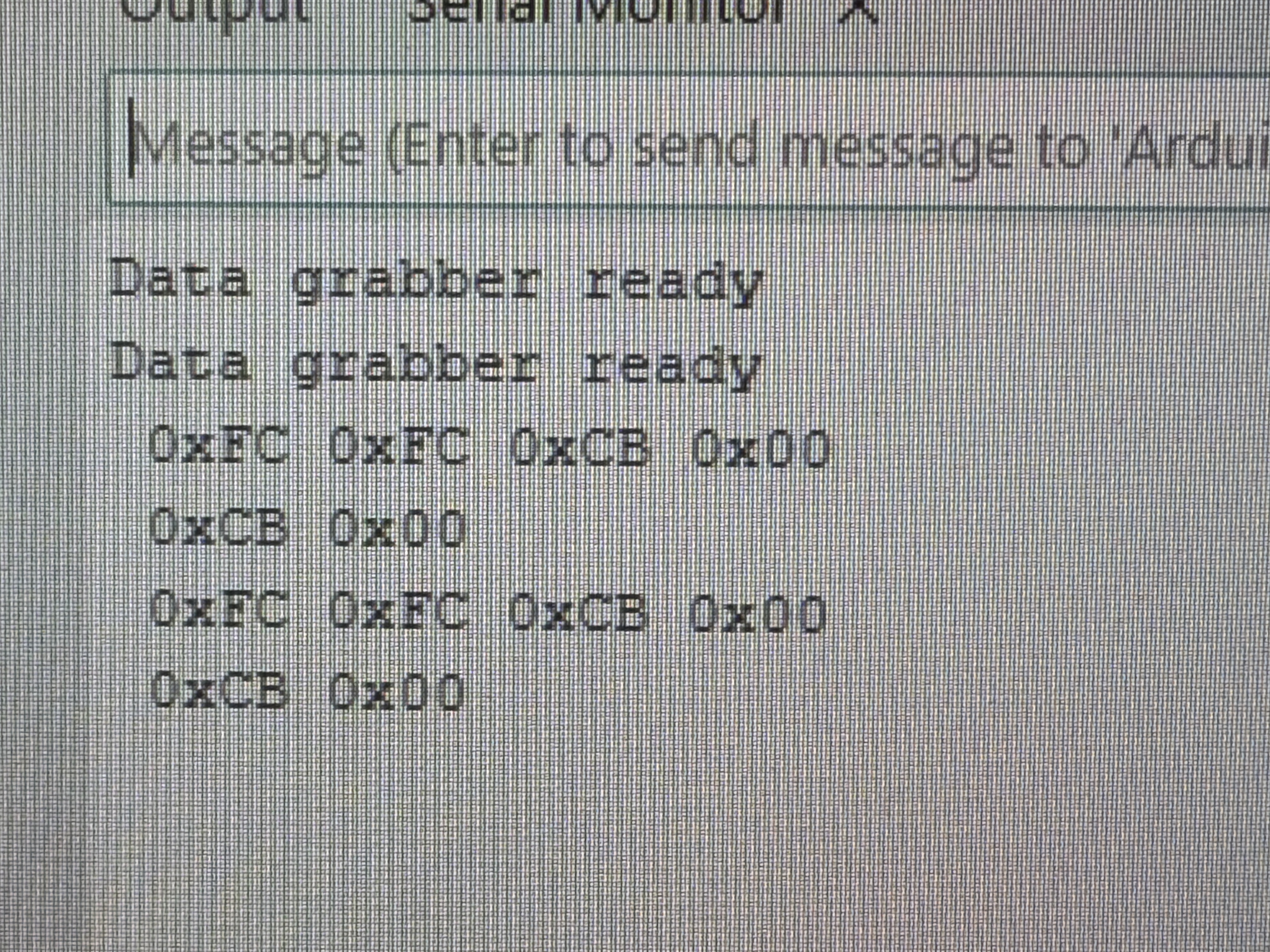
At first I didn’t get anything, but reading the article again helped me. The commands were coming in.
A lot of Hex codes, what’s all this info…
Location: Netherlands
My B&O Icons:
I started a new topic, but now it is marked as spam. That doesn’t help.
Could you please check if something can be done to correct this?
I was only referring to an old topic with a link, further it was just text and a pictureLocation: Netherlands
My B&O Icons:
In which subforum would fit such a project? Then I’ll create a separate post with more information.
The project is in a 80% state of completionLocation: Netherlands
My B&O Icons:
Hi all,
Pretty new here, a few years ago I made an account but never been really active.
I’m working on a networkplayer which integrates in a Beosystem 5000/5500/6500/7000.
Base housing is an old Beomaster 5500 which was in appaling state.
Hart of the system is a Raspberry Pi with Volumio Audio Streamer.
Around this 3 Led Matrix screens behind the frontpanel, An Arduino to communicate with the Beomaster and a second Pi to control the screens.
If you like it I can create a separate topic.
Location: Netherlands
My B&O Icons:
-
AuthorPosts