Forum Replies Created
-
AuthorPosts
-
 BRONZE Member
It appears the cartridge body grounding contact is not being inserted properly. There is a small cutout at the bottom rear of the cartridge that receives this copper contact.

I would return the “remanufactured” part. My guess is that they simply replaced the rubber but never actually tested it.
I would only consider a fully restored 4002 for its musical value and not for its investment. I believe their value has leveled off.
Here you go:
They should not be a problem unless your suspension is adjusted low. If you can put 2 normal records on without bottoming you should be fine. In any case, you’ll not damage anything.
As far as I remember, there is no locking mechanism on the lid. The unit simply detects it going up or down to control the mechanism. If this is a unit that has been in storage or unused, it could have dried damping grease at the two hinges. I would first try using a blow dryer at low setting at the lids back hinge points to soften it. Then try lifting it by both front corners so the upwards pressure is equal.
The knob should adjust the puck in on the copper spring metal shown off the right edge of your picture. If this is not happening, then your only recourse will be an attempt at a repair, as you’ll not find a replacement except from a parts unit, given that it’s almost 60 years old.
26 November 2025 at 03:20 in reply to: Beogram 3000 (Linear) – Tonearm gets stuck in Lift/Lower Loop #71555The Beogram 3000 was designed to fully work via datalink withe the BM3000. While input switching will generally work with older models, other functions can be iffy. There may be nothing wrong with your unit. If your fine w/o using datalink its fine to run w/o those pins. Just don’t lose them! I usually tape them to the TT.
I can’t say I’ve ever seen that particular behavior. Have you replaced all of the electrolytic caps? These can be the cause of intermittent issues and is required for a Beogram of this age.
If that is the case then there must be in inner point in the record where that stops occurring. Is this the case or is it simply having to cue it down a second time that allows it to continue to play? Why this is critical is that there may be something that is causing the solenoid’s arm to withdraw. The circuit switches to a lower current setting to hold it extended which makes it susceptible to being bumped to release. As such I would try it with the outer platter removed and starting it. If it stays down, then you can very gently tap the cartridge inwards to see if it moves without raising until the end.
If you move the arm from the off position directly to the lead-in groove, not relying on the automatic edge detection, and manually cue it down, does it play properly?
17 November 2025 at 23:56 in reply to: Beogram 5000 Help needed please – Video linked showing fault #71361You may have multiple problems, but one appears to be inadequate tracking force. Here is a link to the Soundsmith page that provides a very thorough description: https://sound-smith.com/how-balance-your-bo-tone-arm-and-set-proper-tracking-force.
You really need to take a look at the service manual in the section that discusses the adjustment of the magnet coil. That is where I would start before investigating failing parts. Rudy’s Beolover site also has a complete 4000 restoration that covers that area well: https://beolover.blogspot.com/2024/02/beogram-4000-full-functional-restoration.html.
No you access it by removing the bottom cover.
There is a sliding shorting switch near the base of the tonearm that is activated when the arm rotates to unshort the + and – leads of each channel.
The issue they are trying to address, is that when the weight is removed, the suspension will be higher on that side and the tonearm will show a great distance from the surface. Simply adjust and place it in but not fully seated so that you can check the height.
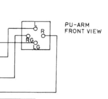
No, its L-, L+, R+, R- .
Grab the edge to the silver plate on the rear of the tone arm and lift it out. It fits using friction.
Since the turntable is supposed to be muted at that point, this is a grounding problem. First, I would move the arm over and cue it down before the edge of the record to see if the sound changes when it unmutes. I will bet it does. If so, then your 3rd party DIN cable does not have the ground wire connected properly. It needs to connect only to the DIN connector sleeve. If it is connected properly, then the issue may be on the connector board in the turntable.
I’m sorry but there was to much traffic noise in your video to zero in the noise you are referring to. What component are you connecting it to and specifically what cable are you using? If you are not using a DIN to DIN cable are you connecting the phono ground wire?
-
AuthorPosts