Forum Replies Created
-
AuthorPosts
-
4 October 2022 at 21:33 in reply to: Strategy for Changing Capacitors and Trim Pots on FM Tuner #39358
 GlitchBRONZE Member
The TinySA can generate signals in the FM frequency band with various modulations, as well as sweeps. I can compute FFT’s with my scope which should give an idea of the distortion?
Glitch
4 October 2022 at 19:40 in reply to: Strategy for Changing Capacitors and Trim Pots on FM Tuner #39356GlitchBRONZE MemberI have looked around for the equipment needed for working on the FM tuners. I originally started looking at used, professional grade equipment. I found myself gravitating towards the equipment that we had in our electronics lab at work in the 1980-1990’s time-frame. Though this equipment has dropped significantly in price since new, most of it is still out the price range that I would want to spend for this project. Additionally, I have the usual concerns about the operating state of such old equipment.
While researching FM tuner repair and alignment, I came across a device that might fit my needs. It is called a “TinySA” (https://www.tinysa.org). This appears to be able to generate the signals that I would need. Does anyone have experience with this piece of equipment? If so, would a TinySA and a 200 MHz scope be sufficient to do the basic adjustments?
chartz: I was reading some old posts in the Beoworld archives. Did you ever get your BM8000 to tune to the higher frequency stations?
Glitch
GlitchBRONZE MemberGood catch on the power cord. Maybe there is a clue in the seller’s name (i.e. ishams*123)? 😉
However, looking at the rest of the B&O stuff that he has for sale, it is probably a legitimate oversight in the pictures. Why scam people on a $50 item when you are selling a bunch of more expensive stuff?
GlitchBRONZE MemberMy first thought was similar to Sia43’s suggestion. Of course the labeling doesn’t make sense, unless, it is trying to indicate which port on the OTHER equipment to hook it up to. For example, SUBWOOFER IN means to hook it up to the input port of the subwoofer.
Otherwise, maybe it is a remixer for someone that has a high-passed center channel and low-passed subwoofer channel and wants to run left and right full range speakers?
I also noticed the lack of an IR connection. Could it be on the side of the box and not pictured?
Glitch
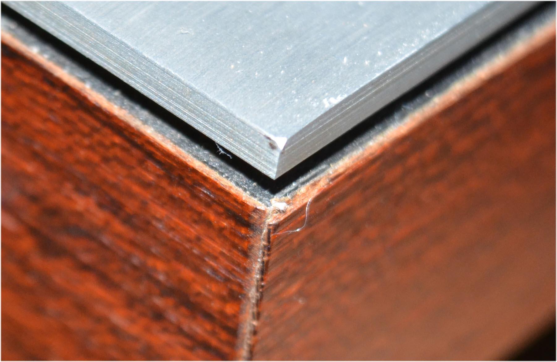
GlitchBRONZE MemberLooks great! That is very beautiful veneer.
How are you going to handle the veneer overlap on the corners?

Glitch
28 September 2022 at 15:34 in reply to: Strategy for Changing Capacitors and Trim Pots on FM Tuner #39354GlitchBRONZE MemberIsn’t most of the “alignment” done with the variable inductors?
My assumption is that these don’t “go bad” and are (very much) to be left alone. Is that true?
Glitch
Note: It is probably obvious that I don’t have ANY experience with messing with the tuner sections. I do have general, theoretical, engineering knowledge and can follow along with most topics.
GlitchBRONZE MemberThanks for letting us know that you got the amp working.
I’m glad you didn’t have to resort to the Beovox option. IMHO, the BeovoxPentas just don’t “look right” once you are used to the BeolabPentas.
Finding a good condition, intact display cover will be a challenge. I had the same problem and ended up with an alternative solution.
Glitch
28 September 2022 at 01:00 in reply to: Strategy for Changing Capacitors and Trim Pots on FM Tuner #39352GlitchBRONZE MemberMartin,
Thank you for your sage advice.
Your reply is pretty much what I suspected. I had to ask in case the settings of the trim pots were far less critical than what I expected. With old equipment it is sometimes hard to judge which is the lesser of two evils, old worn out parts versus new out of spec parts.
My game plan is to stick with “1” if there are not issues, then maybe try “2”. I’ll research what is needed for “5”. My bench equipment most likely falls into two categories, too new (modern digital with all of the digital issues) or too old (like vacuum tube old, my wife’s grandfather’s test equipment). My gut feel is this is a job for quality analog equipment(?)
I’m not too sure if “6” is really an option. One of the reasons that mothballed the stereo equipment years ago is that all of the really good electronics technicians that I knew either retired or otherwise closed down shop. Besides, option “5” sounds like more fun.
The strange thing is that I really have no interest to listen to FM (same goes for cassette tapes). I just like the idea of having nice, vintage stereo equipment that is fully functional.
Glitch
GlitchBRONZE Memberchartz: I haven’t had the need to veneer any of my B&O equipment, but I have used veneer on other things. I second the recommendation for contact cement to attach the veneer to plastic or metal parts. Another option is a heat activated veneer glue. I haven’t used this myself, but know people who swear by it. I assume that you are using a raw veneer and not one with a pre-applied adhesive.
How do you plan to trim the veneer? If you plan to use a razor knife be sure to pay attention to the direction of the grain so you don’t inadvertently split the veneer.
Looking forward to seeing pictures of your final results.
Glitch
GlitchBRONZE MemberI hope that fixes your problem. Best of luck and be sure let us know how it turns out.
Glitch
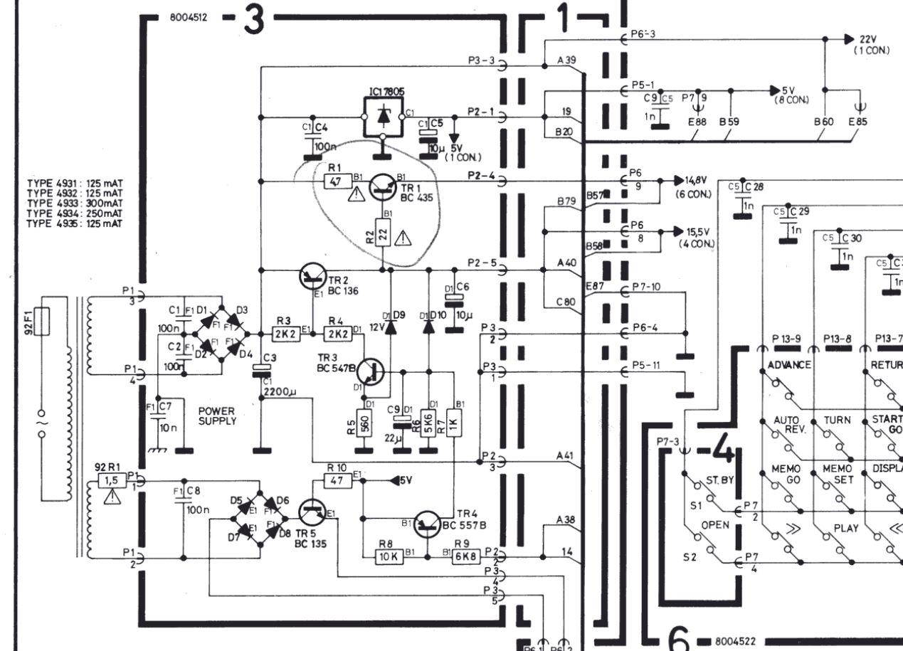
GlitchBRONZE MemberThe deck certainly would not work if the transformer was only putting out 0.018Vac. It wouldn’t even power on to the point where you would see any significant activity on the deck. Since you said that there were DC voltages on the output of the power supply and other signs of life, I would question your readings.
My only guess right now is that you aren’t getting accurate readings from your meter. Have you tried another meter or checked the meter with a known working source? I would try something like a low voltage AC output wall wart if I wasn’t sure that my meter wasn’t 100% OK.
Glitch
GlitchBRONZE MemberI would expect to see readings approximately in the range of 30-40 Vac on pins1-2 and 6.5-9 Vac on pins3-4 for the transformer only. Once P1 is connected to the the power supply board, the same measurements should drop to the lower end of those ranges.
Glitch
GlitchBRONZE MemberIt is not clear to me what you are actually measuring.
For the transformer with a disconnected P1, the places to measure are between P1-1 to P1-2 and between P1-3 to P1-4. This should be done with the A/C setting of your multimeter.

Glitch
GlitchBRONZE MemberNote: I’m basing my comments on the schematic for a BC6500 since I can’t find one for the BC7000. I’m assuming that they are similar enough.
It looks like to test the power supply stand-alone, you could pull P2 and P3 (with P1 connected). I think that you will only see the +5 and a pretty lumpy +22v signals at this point. The +22v will likely be somewhat higher since there is no-load on it.
Grounding P2-2 should turn-on the +14.8 and +15.5v outputs (as well as the +4.2v? output).
I believe that you should be able to debug the power supply in this configuration without the protection circuitry turning things off.
I may of misunderstood your earlier comments. Were you saying that you were seeing 5v A/C on the secondaries while seeing +22v DC on the output of the rectifier? If so, this wouldn’t make sense. Could you have been measuring the second, lower voltage secondary?
I don’t know what the exact current draw for the boards would be. My SWAG would be somewhere in the range of 50mA to a couple of hundred mA. Checking the fuse ratings and scaling the currents can give a rough idea of what to expect as a maximum.
Glitch
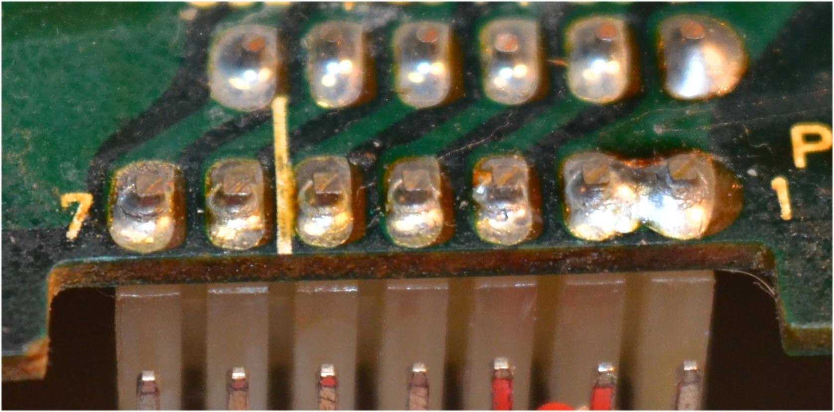
GlitchBRONZE MemberFor reference, the crack at pin 7 is the kind of thing to look for. The “stress rings” around the other pins look like they are getting close to failing.

Glitch
GlitchBRONZE MemberThe transistors and load resistors “look” similar to my working Penta2’s (i.e. no obvious overheating). I wouldn’t mess with them right now.
Probably not the problem, but are you sure you have the trim 100 and 220 trim pots in the correct location?
While you are double checking… check the polarity of the power supply capacitors. I recall that the markings on the original capacitors could be misinterpreted.
The soldering on some of the transistors doesn’t look like I would expect coming from the factory. I would clean-up the flux residue and do a closer inspection. It might be just the camera angle, but the solder from TR32 seems close to the trace.
I would carefully inspect the board connections even if you didn’t touch the connectors. I use either a 7X loupe and a bright light or take a picture with a macro lens and zoom in on the pictures on the computer screen. Even if I don’t find any obvious issues, I usually reflow solder on the board connectors as a precautionary measure.
I had trouble setting the bias on one of my other B&O amps. It turned out to be a bad ground connection to the preamp. The symptoms were similar to what you described where the full range of adjustment on the trim pot wouldn’t get the bias to a proper value.
I am also interested in hearing from others the possible causes for the amp running hot.
Glitch
GlitchBRONZE MemberApologies in advance if you already know all of this…
There is actually a lot going on inside a transformer from an electromagnetic point of view. A detailed explanation of exactly what happens is probably beyond the scope of this forum and would put most people to sleep. A simplified explanation is that the secondary windings have resistance, as the current output increases, the output voltage of the transformer decreases proportionally (i.e. V=I*R or more specifically V_out = V_noload – I_output*R_windings).
If you did a direct short of the transformer output, you would expect the voltage output to go to zero, right? Your circuit board is simply a load somewhere between a no-load and a direct short.
The rectifier doesn’t really change any of the above. All the rectifier does is switch what phase of the transformer’s A/C output is connected to the rectifier output at a given time. The current load on the transformer is still there.
There “could” be a problem with your transformer, but I believe that these kind of issues are rare. Transformers are generally robust and reliable devices that fail pretty decisively.
Have you tried to measure the current draw of your board? This can be done with a multimeter (be prepared to replace the fuse in the multimeter if the current draw is above the rating). A better option is to use a bench power supply with a current limit. Set the current limit to less than you expect the board to draw and increase slowly until you get a better idea of your situation. The bench power supply approach has the benefits of not having to deal with the protection circuitry kicking in and making taking readings difficult, as well as limiting the possibility of further damage to the board.
After you use the bench setup to find/fix any possible power related issues, it will be easier to debug the rest of the functionality.
Note: I would keep following Martin’s advice as it will likely get you to a solution faster. My suggestions are in the spirit of trying to get more information so that it is easier for people to help.
Glitch
GlitchBRONZE Memberalf,
I wouldn’t expect that the transformer is bad. It is normal for an unregulated power supply that the voltages be pulled down under load. Voltages lower than what is indicated on the schematic would imply that you have a short or some other similar fault on the board.
Do you have a bench power supply? If so, connecting the board to a bench supply is helpful for debugging.
A voltage sag from 40v to 5v seems to be more than a “sensitivity issue”. It sounds like a genuine fault and the protection circuitry is doing its job.
Glitch
GlitchBRONZE MemberI’m certainly not an “expert” on these amps, but I’ll try to help by asking some general questions. At the very least, there will be a bit more information here in case someone with in-depth knowledge of the common Penta amps failure modes chimes in.
Are any of the main transistors or load resistors discolored?
What are the actual voltages on the +68v and -68v power supplies?
Did you replace the power supply capacitors?
Have you reflowed the solder on the board connectors? Or at least carefully checked for cold solder joints?
It also might be helpful if you could upload some pictures of the component and trace sides of the circuit boards.
Glitch
GlitchBRONZE MemberDid you replace the trim pots?
-
AuthorPosts