
Home › Forums › Product Discussion & Questions › BeoCord › Beocord 7000 voltage issues
- This topic has 50 replies, 4 voices, and was last updated 1 year, 8 months ago by
 alf.
alf.
-
AuthorPosts
-
25 September 2022 at 05:01 #38683
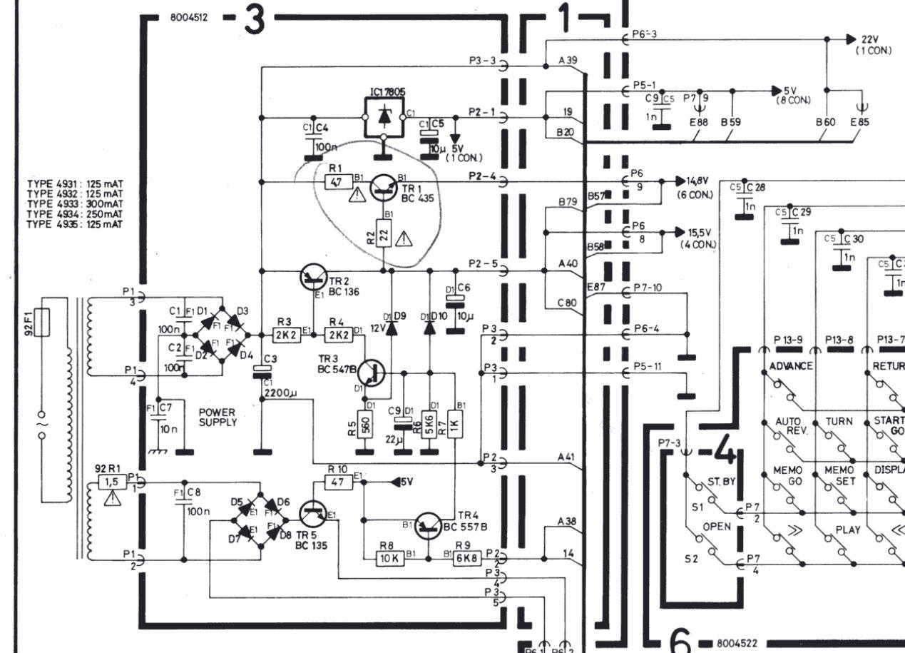
Note: I’m basing my comments on the schematic for a BC6500 since I can’t find one for the BC7000. I’m assuming that they are similar enough.
It looks like to test the power supply stand-alone, you could pull P2 and P3 (with P1 connected). I think that you will only see the +5 and a pretty lumpy +22v signals at this point. The +22v will likely be somewhat higher since there is no-load on it.
Grounding P2-2 should turn-on the +14.8 and +15.5v outputs (as well as the +4.2v? output).
I believe that you should be able to debug the power supply in this configuration without the protection circuitry turning things off.
I may of misunderstood your earlier comments. Were you saying that you were seeing 5v A/C on the secondaries while seeing +22v DC on the output of the rectifier? If so, this wouldn’t make sense. Could you have been measuring the second, lower voltage secondary?
I don’t know what the exact current draw for the boards would be. My SWAG would be somewhere in the range of 50mA to a couple of hundred mA. Checking the fuse ratings and scaling the currents can give a rough idea of what to expect as a maximum.
Glitch
26 September 2022 at 05:40 #38684Ok, another voltage check:
looking at the disconnected transformer and its Plug1 voltages
Pin1/2/3/4 = 42 VAC
looking at the connected to board3 via Plug1 – Plug2 and 3 were disconnected !
pin1 = 5.6 VAC, pin2 = 5.5 VAC, pin3 = pin4 = 0.08 VAC
I do not get 5 VDC nor 22 VDC
grounding Plug2 pin2 via neg of C3 delivers nothing (unless I misunderstood you)
are you still quite confident the transformer is ok ?
ALF
26 September 2022 at 13:01 #38685It is not clear to me what you are actually measuring.
For the transformer with a disconnected P1, the places to measure are between P1-1 to P1-2 and between P1-3 to P1-4. This should be done with the A/C setting of your multimeter.
Glitch
26 September 2022 at 13:26 #38686The AC voltages as you suggested are around 0.018 VAC P1 1 to 2 and P1 3 to 4
when the transformer is disconnected from board 3
does that make sense ! Sorry about the confusion
ALF
26 September 2022 at 13:45 #38687I would expect to see readings approximately in the range of 30-40 Vac on pins1-2 and 6.5-9 Vac on pins3-4 for the transformer only. Once P1 is connected to the the power supply board, the same measurements should drop to the lower end of those ranges.
Glitch
26 September 2022 at 16:09 #38688well, I believe my last measurements were measured correctly.
I can not imagine the deck to work with these kind of voltages, can you ?
there is still the unanswered Q :
is the powerpack (transformer) working according to its specification ?
i checked basically all components on that power supply board (3) without any
further defects.
ALF
26 September 2022 at 16:56 #38689The deck certainly would not work if the transformer was only putting out 0.018Vac. It wouldn’t even power on to the point where you would see any significant activity on the deck. Since you said that there were DC voltages on the output of the power supply and other signs of life, I would question your readings.
My only guess right now is that you aren’t getting accurate readings from your meter. Have you tried another meter or checked the meter with a known working source? I would try something like a low voltage AC output wall wart if I wasn’t sure that my meter wasn’t 100% OK.
Glitch
27 September 2022 at 07:51 #38690Sorry but the multimeter does not lie !
I measure incoming mains voltage which is 244 VAC .
what I can measure across P1 pin 1 to 2 and pin 3 to 4
are about 0.015 to 0.020 VAC and that is the sad fact.
I still believe that powerpack (transformer) is not working as it should, in fact
It probably died a slow death ?!
luck had it that I was able to purchase a replacement one from the UK….so it will take a while till Work can resume.
ALF
27 September 2022 at 19:19 #38691I hope that fixes your problem. Best of luck and be sure let us know how it turns out.
Glitch
28 September 2022 at 02:53 #38692I sense you are a sceptic in regards to the transformer being all but dead….but a transformer that gets 244 VAC input and basically nothing coming out I would at least call “a problem” notwithstanding the presence of possible other faults ?
I only repeat myself when stating that no other suspect components on the power supply board have been detected……the promise of reporting back is a certain once the replacement powerpack has arrived.
many thanks for getting on board to help – very much appreciated ?
ALF
7 November 2022 at 05:57 #38693Ok,
i am back on the BC7000 after receiving a replacement powerpack……sorry to say,
but Glitch was right in assuming the powerpack is ok…..and as far as I can tell it is !
here is what happens:
if I plug in the naked powerpack I measure about 6VAC across pin 1-2 and about
22VAC across pin 3-4.
the moment I connect the powerpack to the PS board its fuse blows – p2 and p3 are still disconnected.
so far I have not found a faulty component on that board nor a broken track that may be responsible for the constant blown fuse in the powerpack ???
every single component I tested was fine which begs the question ‘where from here’ ?
Obviously there is a problem I can not see nor measure.
ALF
7 November 2022 at 10:16 #38694Put a 12V 5W light bulb … or 2 of them inline … in the overload line. Replace the fuse with the lights.
If you have a light, then there is a problem.
I told you, that the motor has caps inside (!!!). Check it.
7 November 2022 at 11:34 #38695ok, here it goes:
the PS board is isolated from the rest of the deck incl the tape drive.
just a side issue:
i checked the capstan motor function with a benchtop ps independent of the
powerpack and is was running fine.
i can guarantee the bulbs would come on – so far I blew at least 5 fuses, and they were the correct ones.
ALF
7 November 2022 at 15:21 #38696Disconnect the drive… and use the bulbs to save money.
7 November 2022 at 16:19 #38697Beocords mains voltage setting configured correctly for 220-240V?
Martin
8 November 2022 at 02:12 #38698Absolutely correct Martin as it was before !
thanks for asking…..
ALF
8 November 2022 at 02:14 #38699The PSU does not see the drive as P2 and P3 are disconnected as the link to
the rest of the deck – in other words it should not matter
ALF
8 November 2022 at 13:06 #38700Have you ever seen this BC working? With your own eyes or ears?
Are you the owner? Or bought it later? With unknown defect?
OK, start again.
Call it transformer. If you connect the transformer to the regulator power board it blows the fuse.
Easy. Connect a regulated powersupply instead the transformer to the regulator board.
Maybe one of the 4 diodes of the rectifier have blown. Or C3 2200uF has a short.
But if the BC could be working in Standby and reacted to keys… and then it blew the fuse: C6 10uF is dead.
Were any caps already replaced? In the correct polarity? A cap in wrong position will make you have a nice day…
8 November 2022 at 15:52 #38701i used the deck for years mostly with cassettes, recorded from a radio program.
during those years I owned the deck which is part of my 7000 system.
i say it AGAIN:
every component has been tested off-board from the PS-board…no adverse findings.
C3 has been replaced just recently and meets its spec.
don’t have the circuit diagram in front of me but I presume C6 is on the PS board – yes, tested at 9.1uF. and dto all rectifier diodes………
don’t i need two different DC voltages -two rectifiers, remember !!
ALF
12 November 2022 at 10:34 #38702Ok, time for a confession ?
i do remember the marking on C3 = 2200uF was confusing but I thought I read it correctly…..no, I did not as it turned out and put it in the wrong way. That was the reason of many blown fuses in the power-pack. That is ow rectified after going over the whole board once again.
measuring on the power-pack across pin 1-2 = 6 VAC and pin 3-4 = 22 VAC.
at D3-D4= 29.8 VDC but at D6-D8 = 0.7 VDC which can’t be right ?!?!
Could this point to a leaky diode ??I tested D5 to D8 but all tested ok quasi off-board. Well, in the end I had a nice day !
still, I am getting basically nothing at the pins on P2 or P3…..in other words, more help
is badly needed…..definitely no StandBy dot visible.
ALF
-
AuthorPosts
- You must be logged in to reply to this topic.


