Forum Replies Created
-
AuthorPosts
-
 BRONZE Member
Get a 47uF Vishay instead – then it will read CD-R and CD-RW as well.
Location: Copenhagen
Thank you for the help, Martin. The issue was TR19. It measured slightly strange, so I changed that one first. Solved the problem. Now I have a fully function Beomaster 7000 again.
Location: Copenhagen
I could use a little help here. I have 30V AC on P23 but no AC on the input of Bridge Rectifier D2. I therefore presume that the bridge rectifier is not working properly. I tested the relay RL1 and that works fine when you plug the unit in (it says a click) but it does not say a click when you turn on the unit as it should. However, it tests fine. I guess again this is because of D2 not working properly. Any thoughts?
Location: Copenhagen
All voltages on P14 are correct, however there are no voltages on P15.
Location: Copenhagen
Yes, the display shows the channels without fault.
I discovered today that the BM does not remember the clock and date even though I had just stored them. (Edit: I had not pressed STORE, only ACCEPT).
The lithium battery and caps were changed a while ago, so they should not be any cause for concern. Also, the two muting relays were changed.
Location: Copenhagen
Reviving this thread.
I got my BM7000 back from a repair guy yesterday, and it worked as it should. I played radio, records and CD for 5 hours or so. Turned it off, and this morning the old problem is back again.
The unit turns on and reacts on remote commands but there is no sound. On my Beolink 5000 and 7000 it says RADIO STOP. Also when on radio, the locked symbol does not light up. I was lucky to get the radio channels working for 2-3 minutes and then the locked symbol lit up. And then all of a sudden the sound was again not there and also the locked symbol disappeared. No inputs give any sound but the Beomaster can control all functions. I will obviously return it to the guy who repaired it but at this point I am more inclined to source another BM7000.
Location: Copenhagen
11 August 2024 at 00:44 in reply to: BeoSound 9000 Mk2 Continued CD issues after laser replacement (2x) #58147If it won’t read the CD, the main suspect would be capacitor C2103. It’s a 33uf capacitor.
Location: Copenhagen
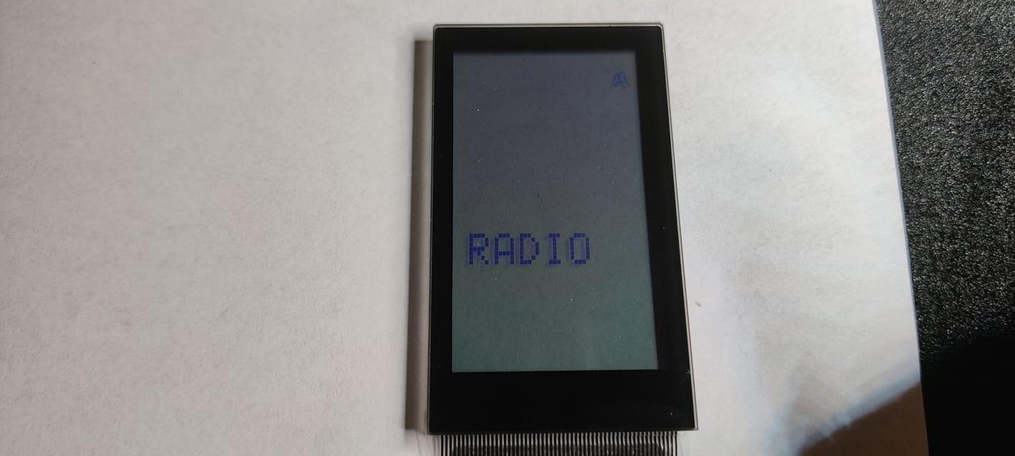
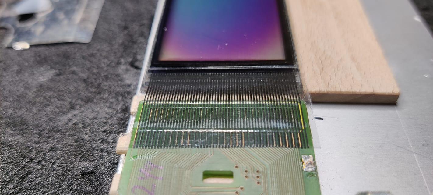
I just completed renovating a Beolink 5000 with new capacitors and new LCD cable (supplied by a very nice fellow on Beoworld)

Location: Copenhagen
Hi everyone,
I am happy to report back that I was contacted by a nice fellow on Beoworld. He had seen that I had been looking for a solution for fixing the Beolink 5000 for a while, to no avail.
He wrote to me that all I had to do was rip off the old LCD cable and clean the print and screen for the glue that was used and then either send it to him or come to his place. I have three of these wonderful remotes but only one of them was working, and with a lot of pixels missing. So, obviously I was very interested. I was also a bit reluctant to remove the cable from the one remote that actually worked but I still did it.
So, I tore off the LCD cables and cleaned the screens and prints, and then I drove to his place just outside of Copenhagen where we had a great talk about Bang & Olufsen, and how we got bitten by the bug. I handed him the screens and prints, and he said that they would probably be ready within a week or so. I also received quite a few spares that I needed to make my Beolink 5000s look almost like new. The price was also very, very acceptable. Thank you!
Sure enough, after a week, he called me and said that the LCD cables had been fixed by a guy in Struer, Denmark.
I have now assembled the first of the Beolink 5000s and I wanted to share the result with you. The screens are working 100%, and I just love the result.
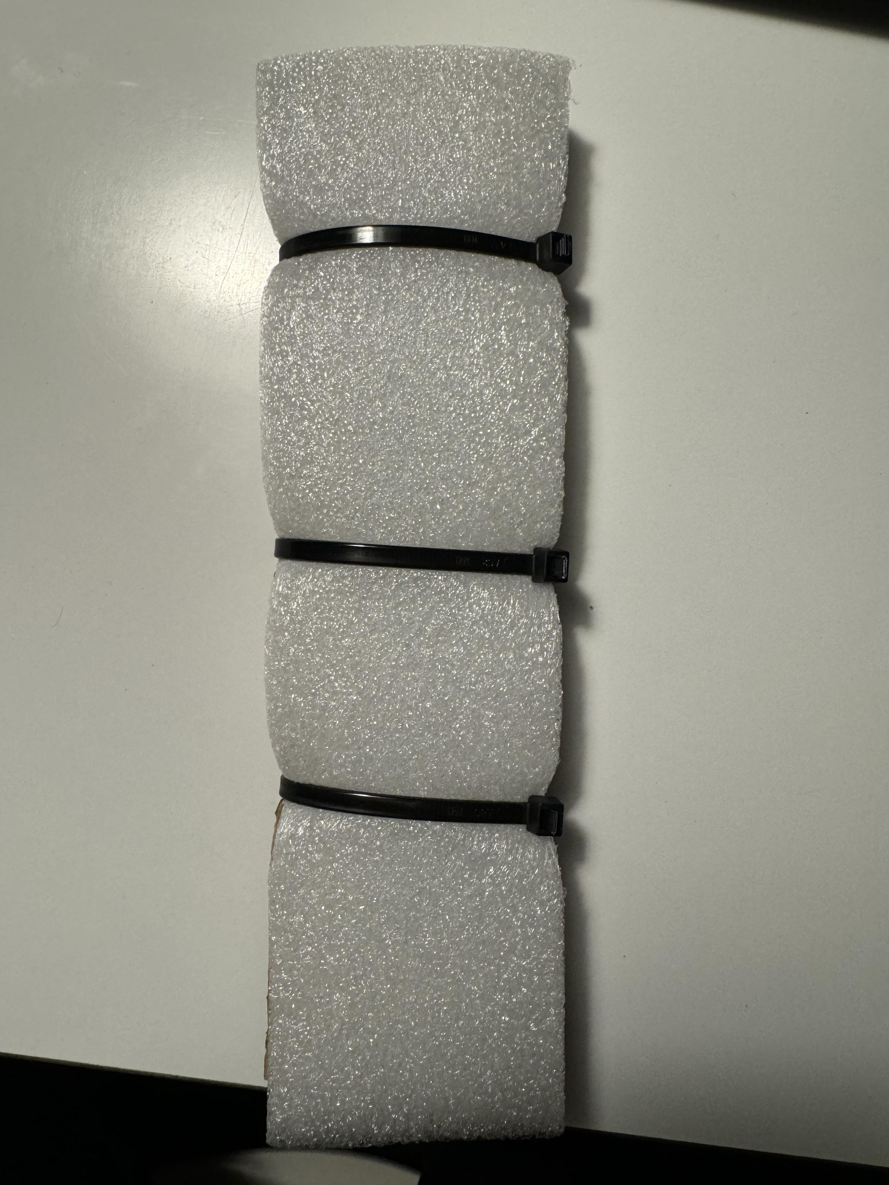
The screen and print are fragile so they were packaged very securely.

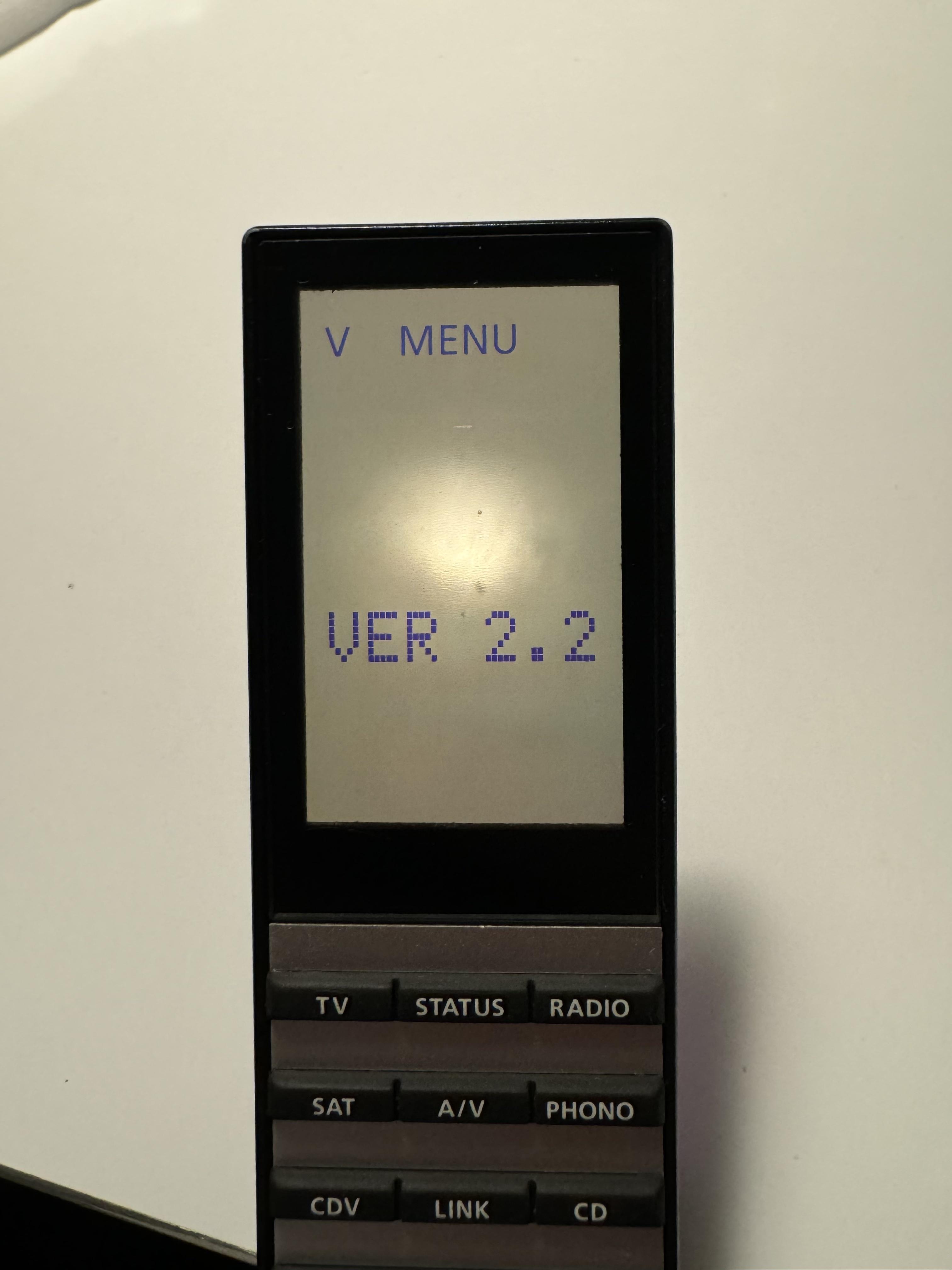
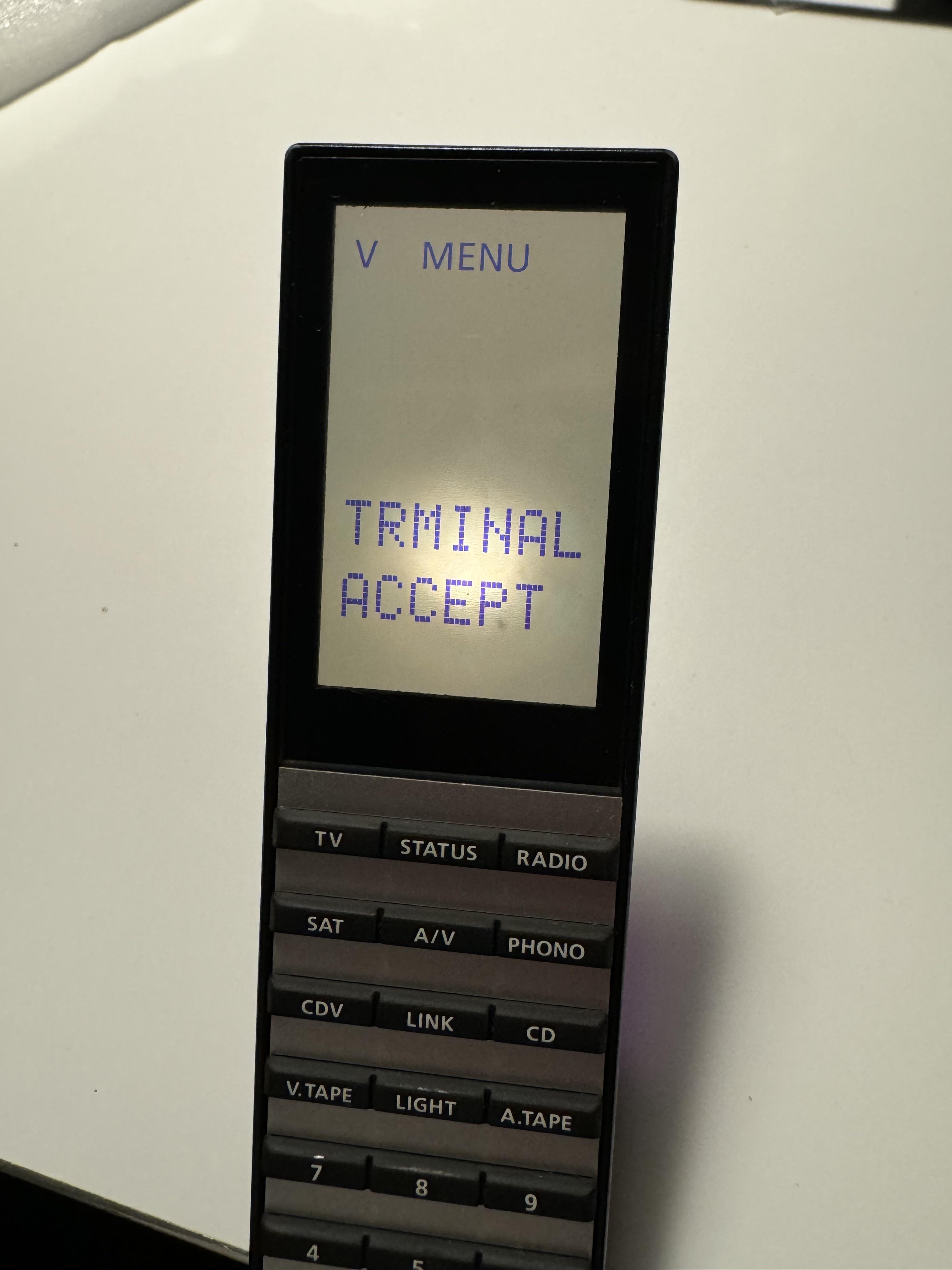
Checking the software version:

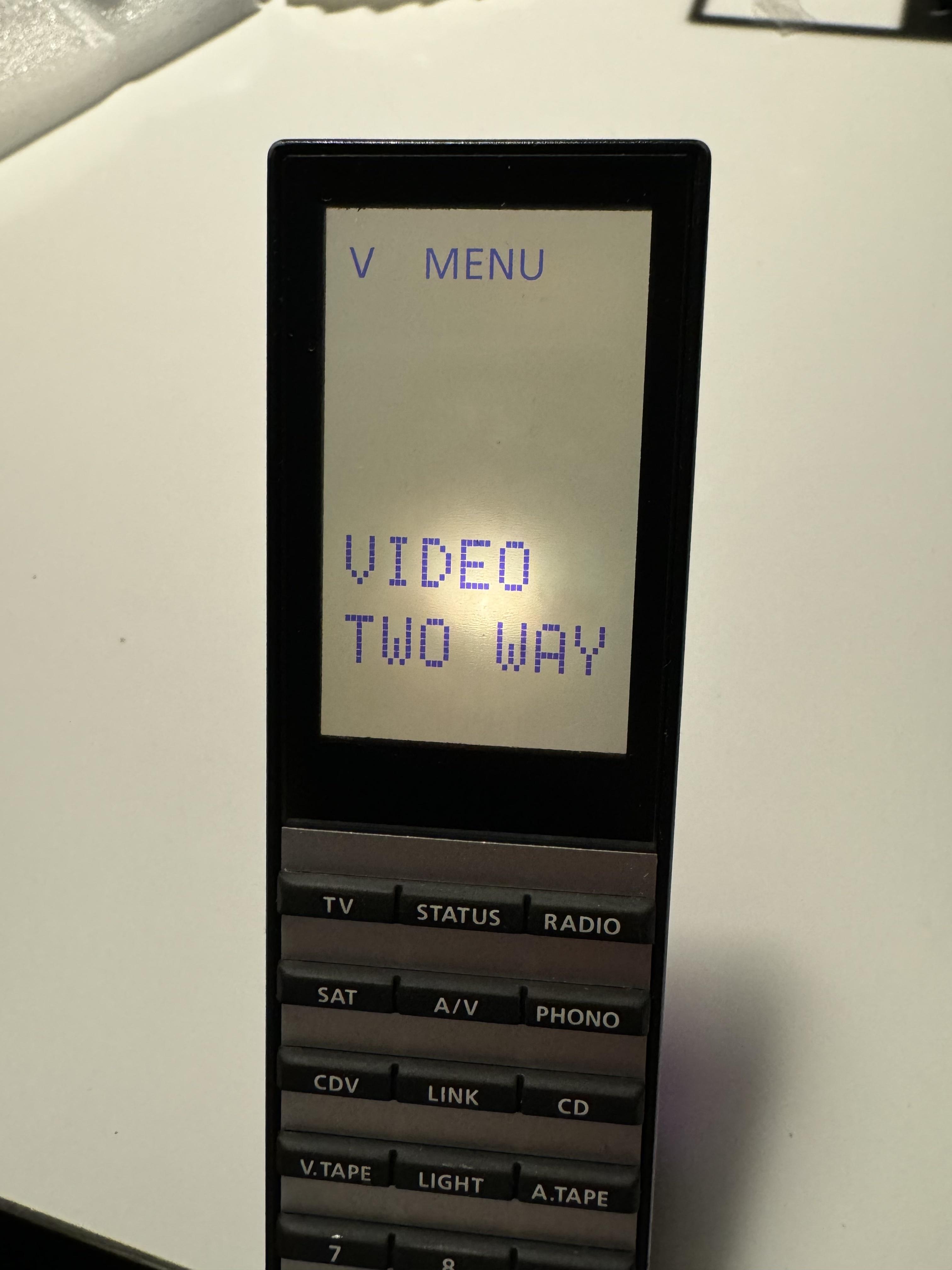
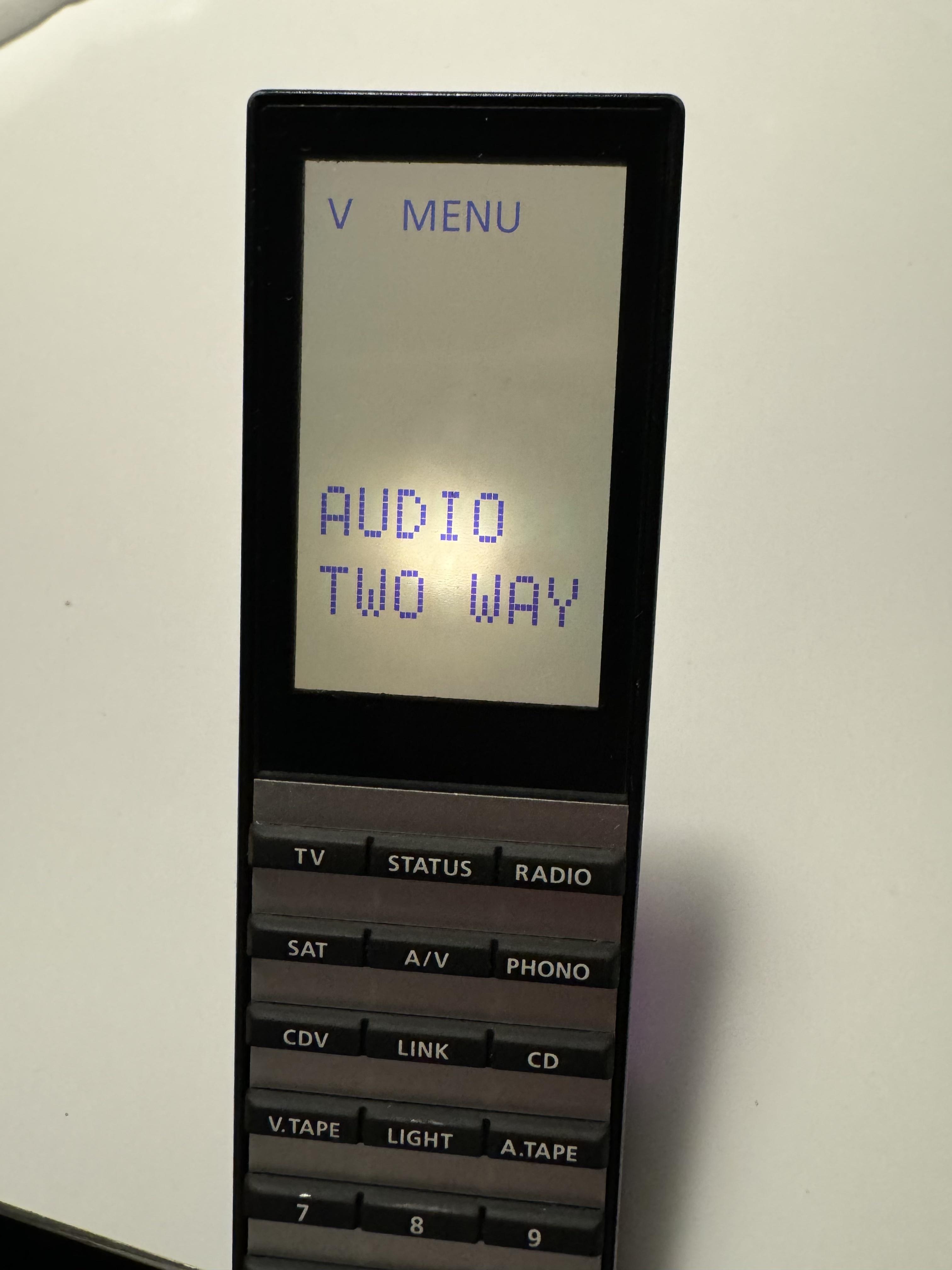
Setting up the remote for one way or two way communication:

Storing:
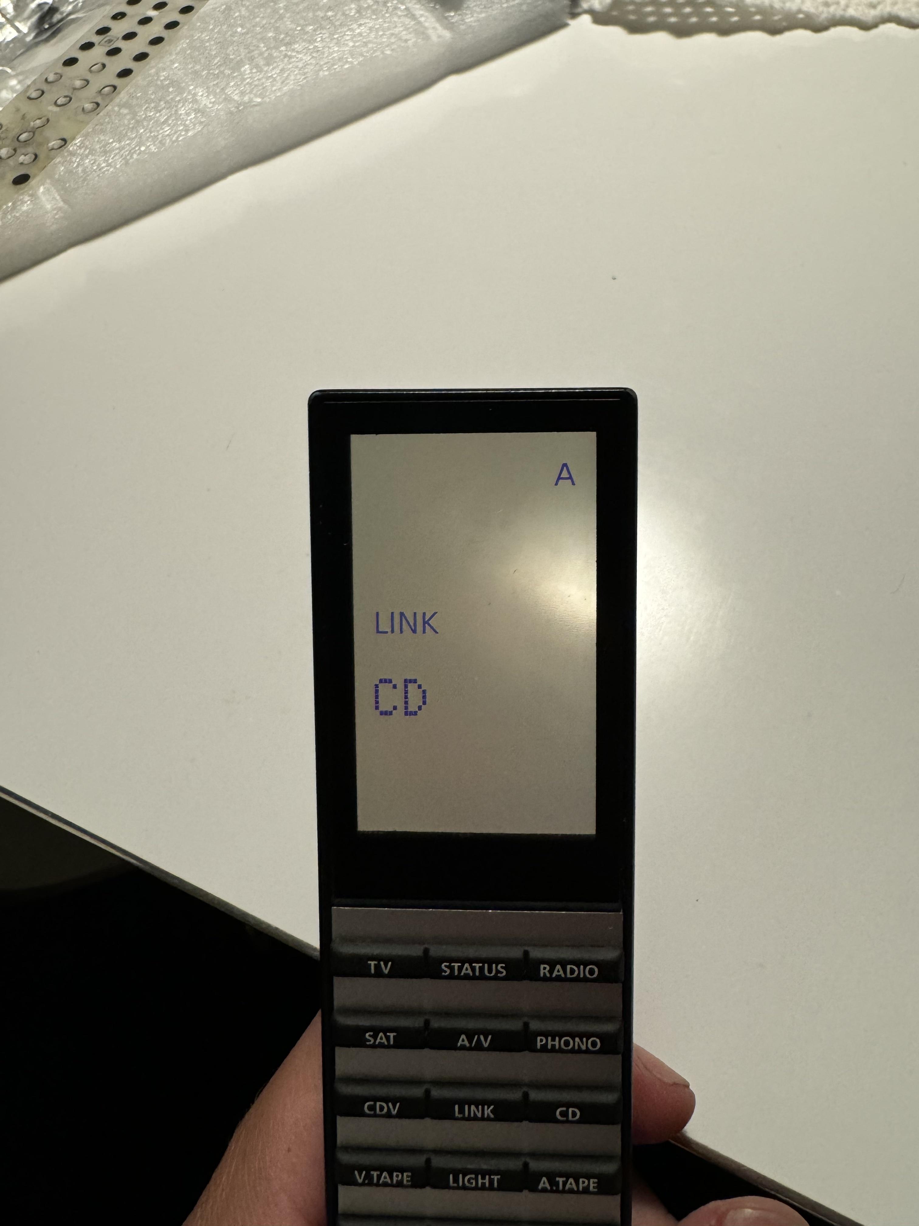
Using Link CD

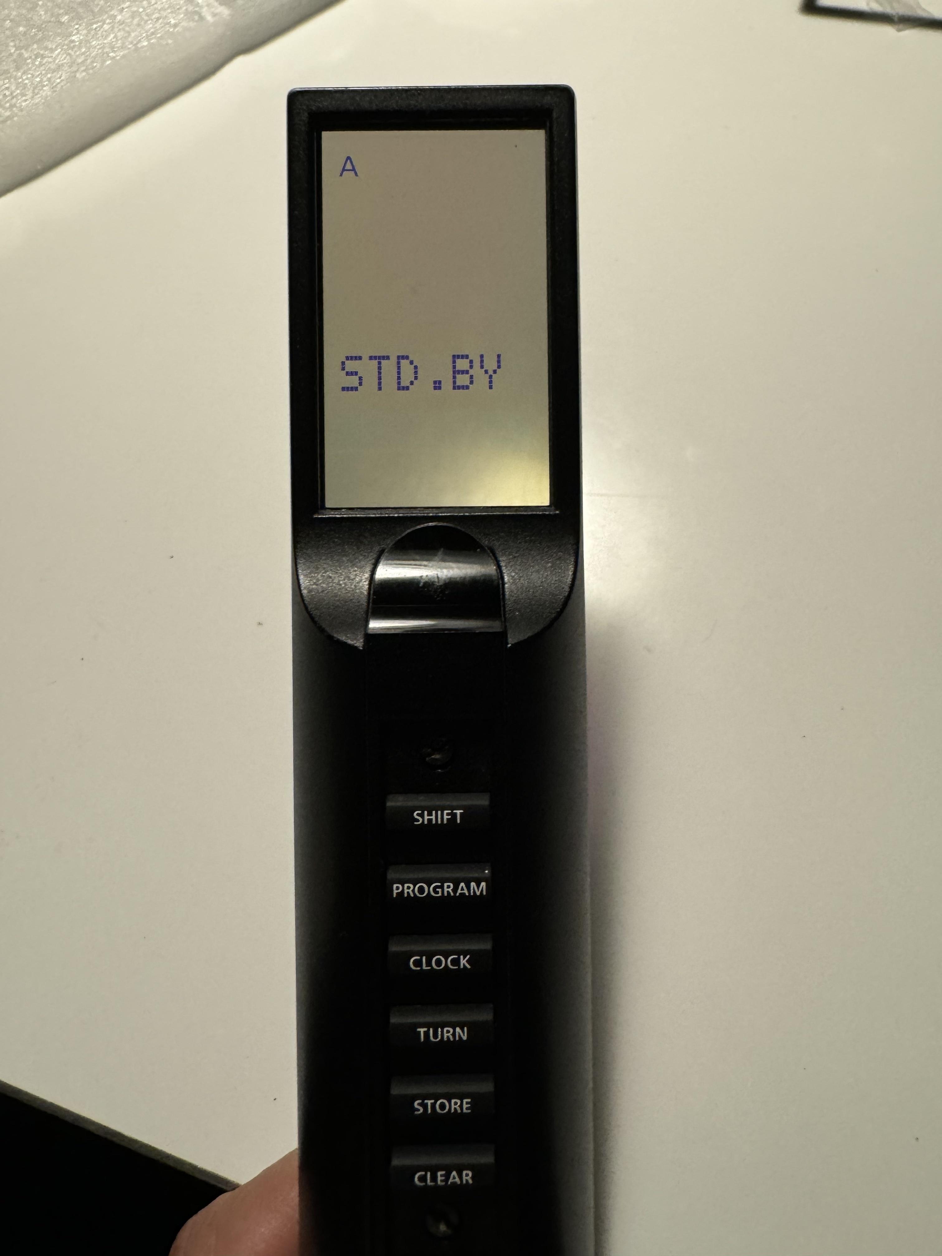
Testing the back display:
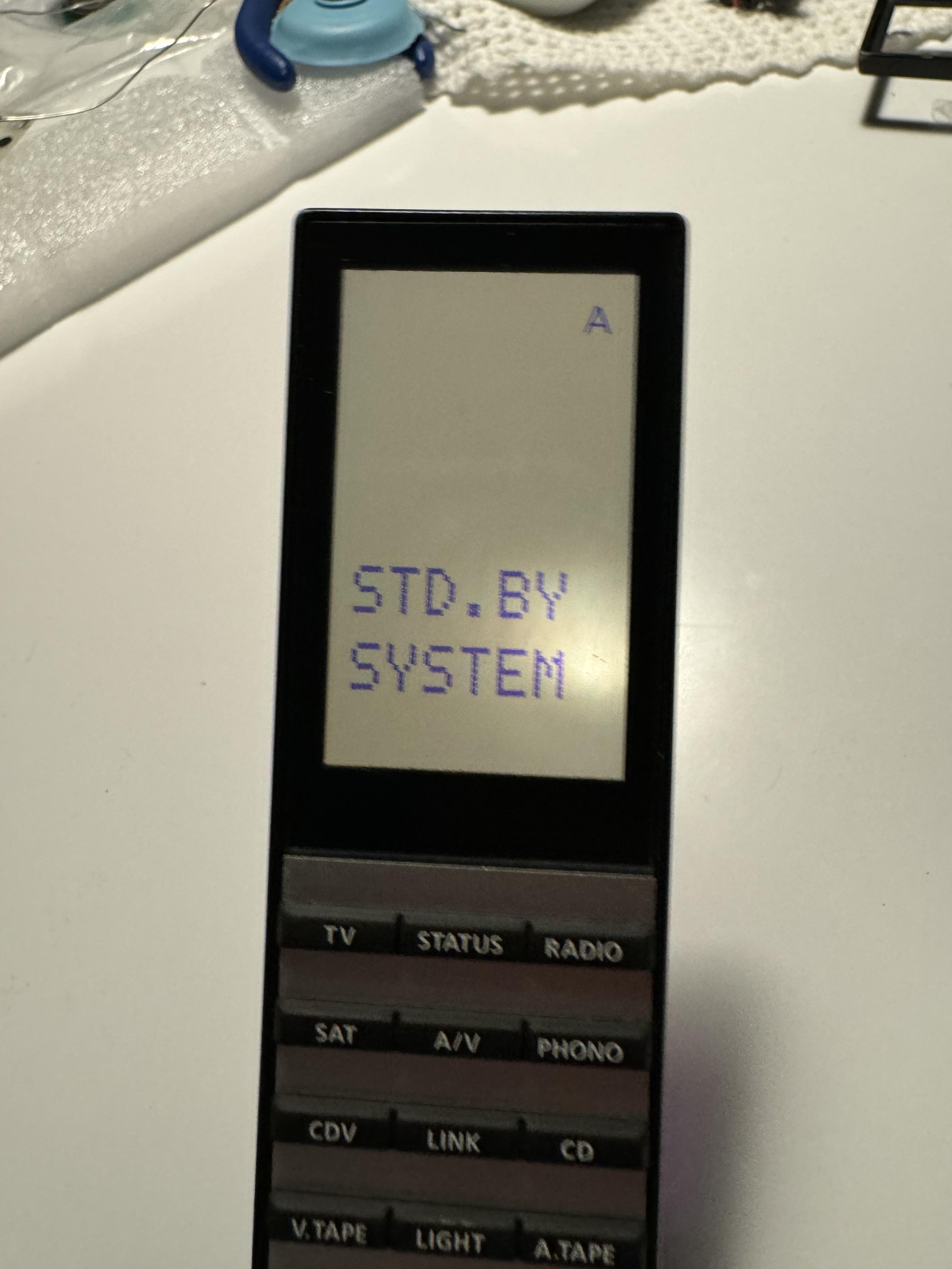
System shut off:

So there you have it. After all these years, a guy from Beoworld has the opportunity to fix the faulty LCD cable and replace it with a new one.
I am very happy right now 🙂
/Filip
Location: Copenhagen
The RIAA on my Beogram 7000 sounded a bit muffled, so I decided to order Martin’s RIAA capacitor upgrade kit.

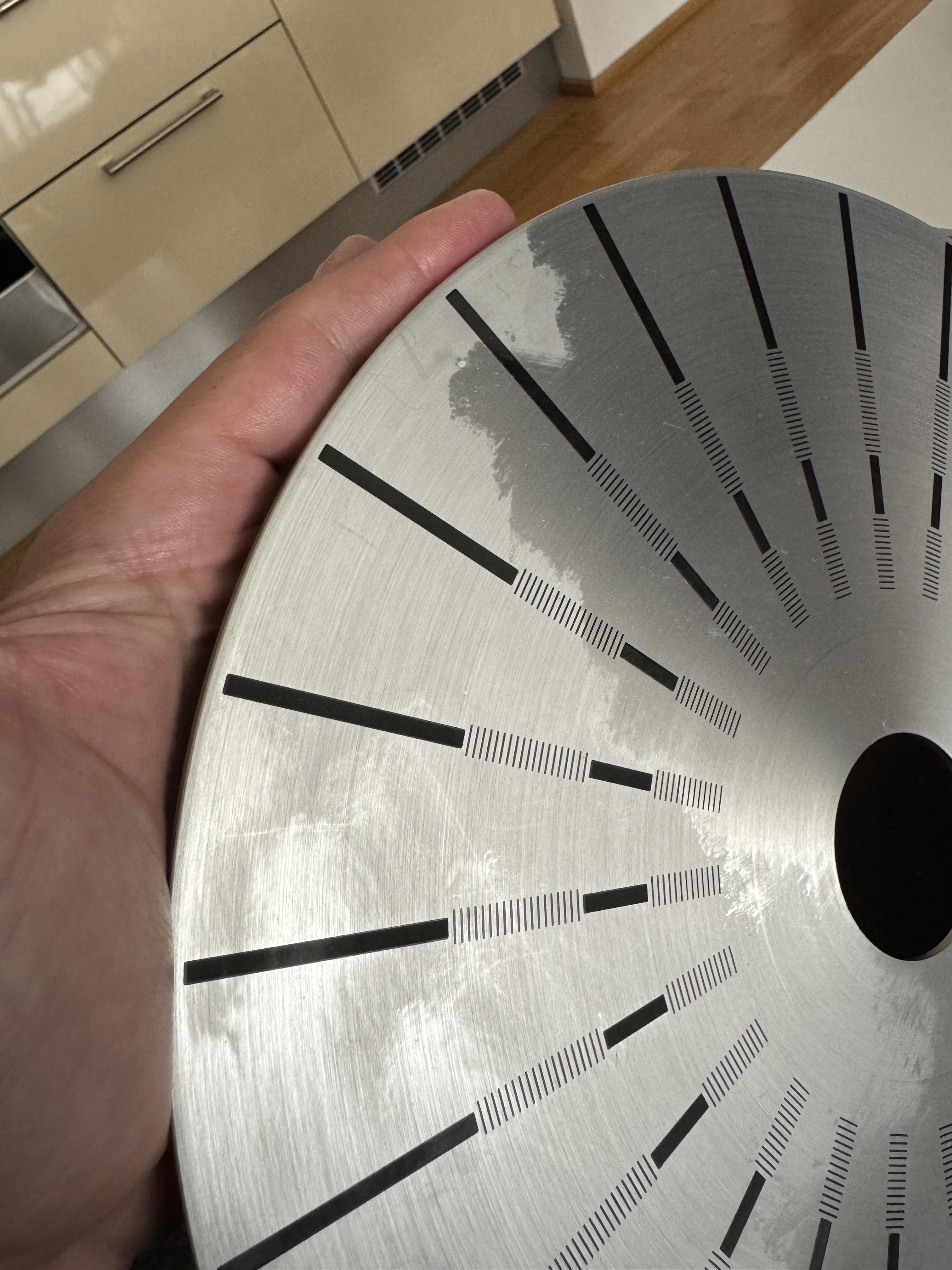
It didn’t take long to change the nine capacitors. After that I decided to polish the platter with coconut oil. I used a cotton pad (the ones for removing make-up), put a bit of coconut oil on it and rubbed the platter very lightly.
Here is the before picture – the dark areas I have already used a bit of coconut oil, they light grey areas are before. I thought it was clean but apparently there was a bit of corrosion or whatever on it.

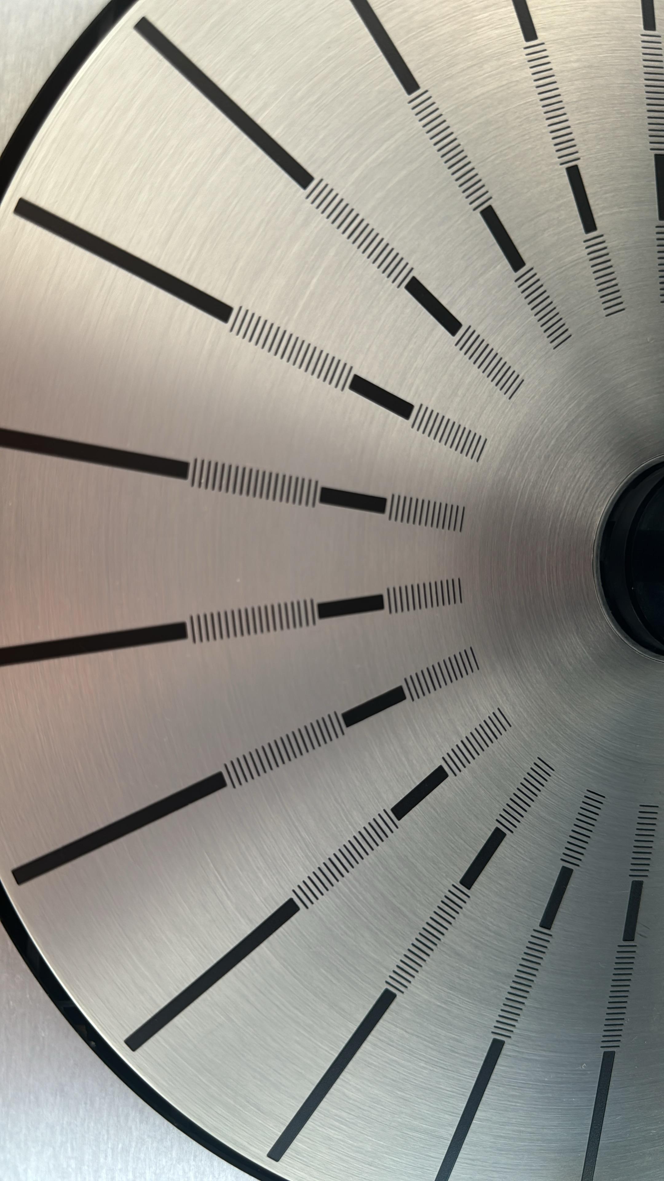
Here is the after photo:

One thing that annoys me slightly about the Beosystem 7000 is that the tactile touch of the buttons on the Beogram 7000 and Beogram 7000 CD feels different and gives a different click sound to that of the Beocord and the Beomaster. I wonder why they didn’t use the same type of switches?
Location: Copenhagen
From RS Baarstrøm on Facebook:
“The method is simple. You have to find a new LCD cable with a pitch of 0,55mm.
Then you align the cable with the screen and pcb and attach it with a heat press.
It is nearly impossible to do by eye, I had to build a simple fixture for alignment and use a microscope.”
Location: Copenhagen
I changed Tr31 and Tr36 but the unit is still dead. A relay clicks and the tape motor runs but that’s it.
Location: Copenhagen
Yes – thank you.
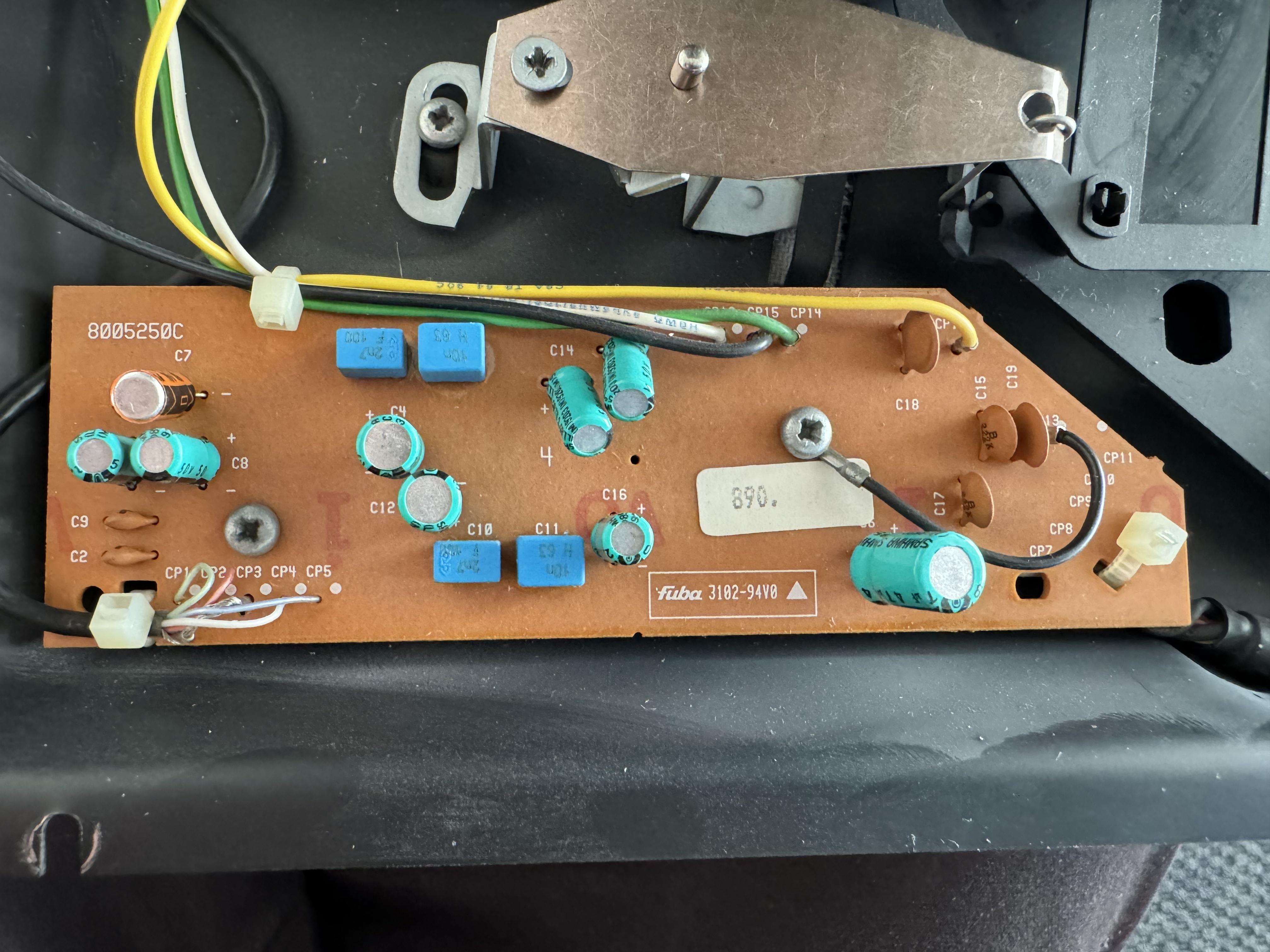
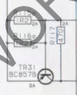
I have now turned my attention to board 10. Since I am getting 24V on P74-1 (and it should be much less – 7.8V unregulated), I am looking at TR36, and it is not working properly, so I will have to replace that.
However, it puzzles me that there is seemingly a short on the board. TR31 measured a short, so I took it off but even without the component, I still measure a short 🙁

Location: Copenhagen
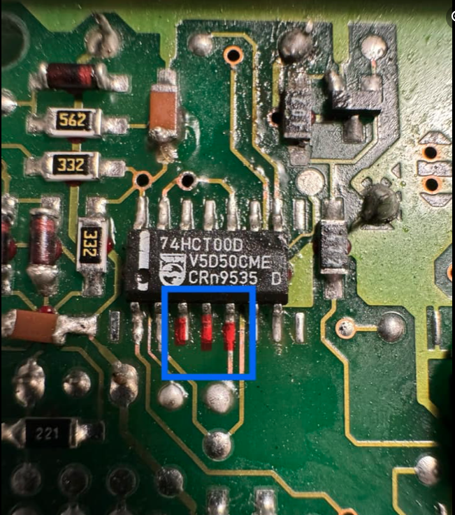
Turns out the three pins get the same signal but there was a broken trace under the IC.
Location: Copenhagen
Hmm – these three legs are shorted. Am I right in assuming that they shouldn’t be? It’s pcb3. When the board is not connected, the BeoCenter starts up with two relays and the tape motor kicks in. The chip is right under the battery damage on the other side, so who knows what’s underneath of great surprises.

Location: Copenhagen
Can someone please upload a clear, zoomed in picture of the cpu board front and back? The service manual scan is not very clear.
Location: Copenhagen
I think there’s still an issue with the micro processor board. I realise I made a mistake repairing the dead track but now that it’s fixed to the right points, there is no relay clicking. I did experience that some of the panels lit up but I don’t know what I touched prior to that. Argh.
Location: Copenhagen
When the motor is spinning, pin 3 gives 15V – but it is not every time the plug is plugged in that the motor will start.
Location: Copenhagen
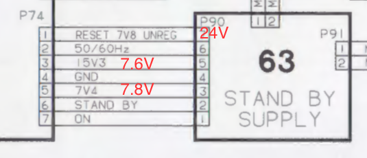
After changing the three diodes on the standby board plus fixing the trace on the processor board, the tape motor now spins but that is all. I still don’t know why I have 24V on pin 7 when it should be 7.8V. My measurements in red below. I am also missing a 15V supply.

Location: Copenhagen
Yeah those batteries can make a mess. I don’t know if it is just the picture, but it looks like there is a crack in the diode D5
Indeed, it does look that in the pictures. I have just re-opened it and tested D5, and there is no crack, and it measures fine. But thank you – because I originally forgot to test that diode. Now, off to my favourite all too expensive diode pusher.
Location: Copenhagen
-
AuthorPosts