


Home › Forums › General Discussion & Questions › General Discussion & Questions › Upgrading a Beogram TX-2 to Beogram 7000 specification
- This topic has 12 replies, 2 voices, and was last updated 1 week, 3 days ago by
 TK.
TK.
-
AuthorPosts
-
9 January 2026 at 01:46 #72440
 TKBRONZE MemberI’ve been enamored with B&O Datalink-enabled systems from the 80s and 90s for the better part of a year now, but I’ve struggled with the cost of acquiring a Beogram 6500 or 7000 due to the <ahem> lofty retail price premiums they command these days. So while I wait for the right system to come along, I’ve been bottom-feeding off of eBay, buying a few early non-working tangential Beograms to get a feel for the technology. I’ve made the discovery which is probably known to most who have been doing this for a while: apart from a very few things like an RIAA board and a different audio cable, there is almost zero difference between a TX-2, 5005, 7000, and up to the 9500. Inside, they are essentially the exact same model. This is both great and depressing news – great, because it means that you’re not getting much extra for your money with a more costly purchase of a higher-number model. But also sad, because it means that B&O basically stopped innovating the Beogram in 1985, leaving it to die a slow death.
I’ve found many posts over the years where folks have discussed what can be done to improve the TX-2 (which is generally the cheapest of the bunch), but no real hands-on guide. So when an inexpensive TX-2 popped up on eBay, I decided that I’d make a bid for it, with the plan of putting one together.
It arrived today, so I set off by giving it a spit-shine, and testing basic function. It’s a suitable candidate for a refreshtoration, so off I go. I’ve got 3 main objectives: 1) Refresh the board, and add the Datalink transistor; 2) Replace the output wire with a Din-7 plug; 3) Create an inexpensive RIAA board, and upload the design to PCB Way to produce (Perhaps there is a forum member who would be willing to share their existing files).
Attachments:
You must be logged in to view attached files.9 January 2026 at 02:02 #72442TKBRONZE MemberFirst things first – does the TX-2, in fact, ship with Datalink enabled?
Early answer: yes, it appears so. But more testing is required to verify the entire instruction set.
I’ve been postulating on this for the past month, trying to find a definitive “it does” or “yes, but there’s a catch…” post, but I figured I’d have to do my own testing anyways. So before changing out the RCA output cable, I thought I’d run a quickee test of the Datalink channel on the main board, to see what signals were being sent, if any. I attached a signal analyzer to the board output (going from CPU pin 19 through some circuitry to pin 1 of the white connector) and measured the results. Presto: Datalink. I received both a “No Media” signal and a “Status Playing” signal, depending on whether I held the record sensor down. With this experiment done, I’m quite confident I’ll be able to attach a Din-7 cable to the output board, and use the Datalink features on a Beomaster 5500, at least. For the later units, I’ll still need to find or create an RIAA card.
Attachments:
You must be logged in to view attached files.9 January 2026 at 06:49 #72446adyanBRONZE MemberHello again,
as already answered here I have done this with my TX2. I have PCB´s of my RIAA left, if you like to get one send a private message.
Details:
7 March 2026 at 00:07 #75706TKBRONZE MemberI’ve had the opportunity to tinker around a bit with a few TX-2 / 5500 PCBs – I used to think that they are nearly identical across the various iterations of Beograms from the 3000 to the 9500, but it turns out there were additional subtle improvements, as one might expect with the introductions of several models. I’ve outlined some of the changes that I can spot – perhaps there are more changes that others know of.
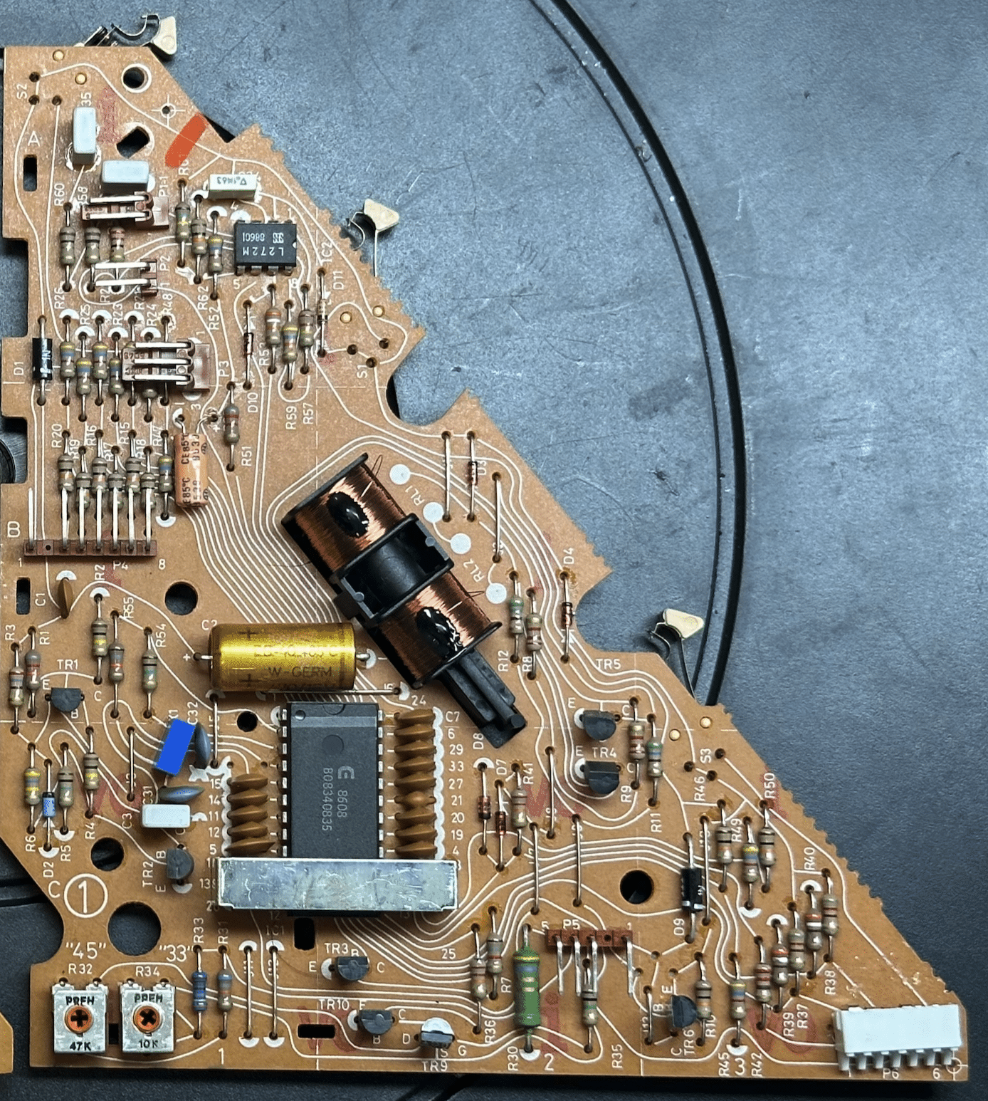
Here’s an example of an early 5005/TX-2 board:
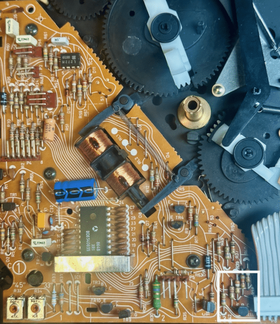
 A 5500 board looks like this below. It adds a Transistor TR11, whose stated function is to keep the Datalink network working even when power is cut to the turntable. Early 5005 boards did not have this transistor, and B&O must have discovered that Datalink stops working if the 5005’s power is cut, driving the CPU I/O low:
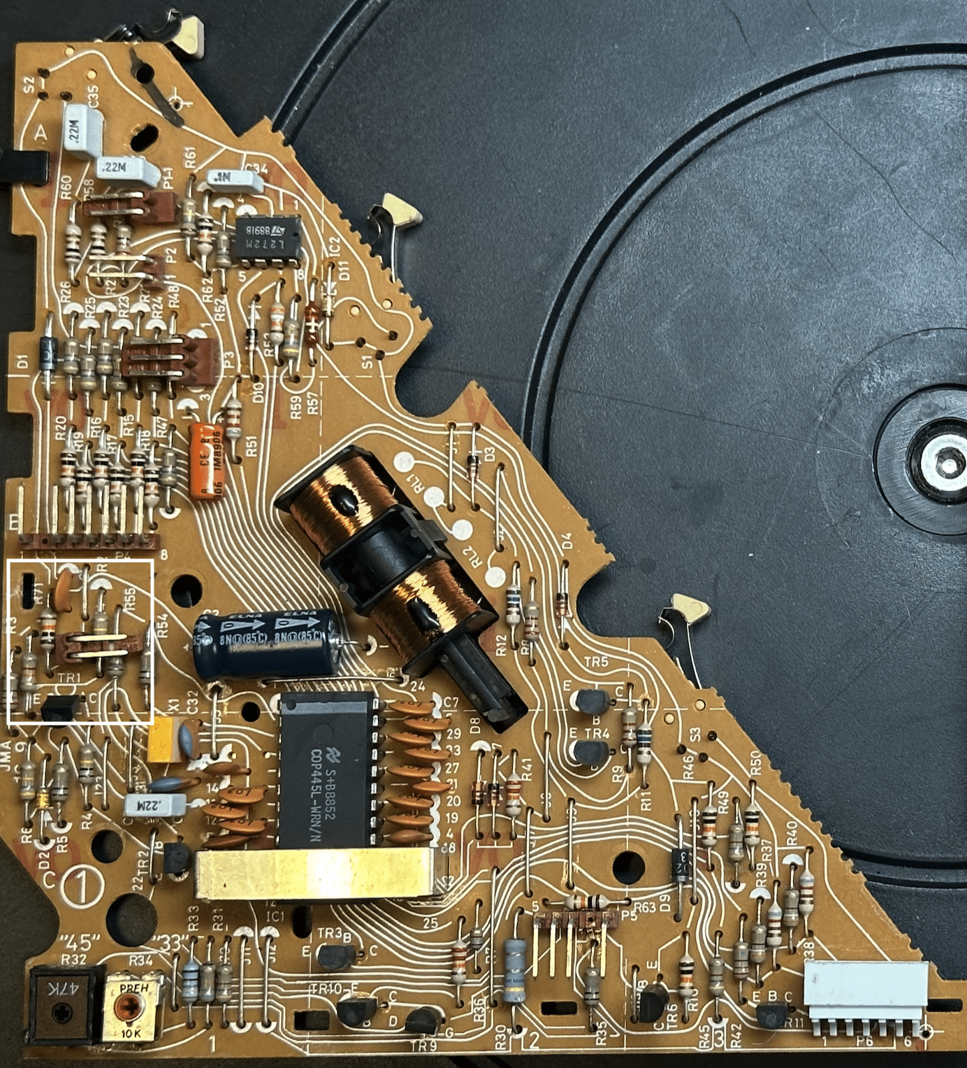
The last board I have for comparison is a late board from a TX-2, which has all the modifications used in the 7000 that I am aware of. In addition to the TR11 (which is only used for the 6500/7000), it also has a new microprocessor with a dedicated pin running to the front-facing “play” button. I’m taking this to mean that the outside button is now meant to function as an “play/off” switch, as opposed to a “play/repeat” switch:
With respect to the differences, it’s a fairly straightforward procedure to add the TR11 transistor, which I’ll do for this upcoming specification upgrade. This also serves to decouple the CPU from having direct exposure to the Datalink pin, hopefully giving the CPU a bit of protection from problematic external hookups. There’s not a whole lot I can do about implementing the “Play/standby” function vs the “Play/repeat” function, as I want to use the late board I have (the one with all the upgrades) in a 5500 upgrade instead of a TX-2. More on that upgrade in a little while. For now, I’m going to add the TR11 upgrade, and call it good enough. I’ve found a few other improvements (mostly to support the addition of RIAA) which I’ll detail in a subsequent post.7 March 2026 at 06:10 #75784TKBRONZE Member
A 5500 board looks like this below. It adds a Transistor TR11, whose stated function is to keep the Datalink network working even when power is cut to the turntable. Early 5005 boards did not have this transistor, and B&O must have discovered that Datalink stops working if the 5005’s power is cut, driving the CPU I/O low:
The last board I have for comparison is a late board from a TX-2, which has all the modifications used in the 7000 that I am aware of. In addition to the TR11 (which is only used for the 6500/7000), it also has a new microprocessor with a dedicated pin running to the front-facing “play” button. I’m taking this to mean that the outside button is now meant to function as an “play/off” switch, as opposed to a “play/repeat” switch:
With respect to the differences, it’s a fairly straightforward procedure to add the TR11 transistor, which I’ll do for this upcoming specification upgrade. This also serves to decouple the CPU from having direct exposure to the Datalink pin, hopefully giving the CPU a bit of protection from problematic external hookups. There’s not a whole lot I can do about implementing the “Play/standby” function vs the “Play/repeat” function, as I want to use the late board I have (the one with all the upgrades) in a 5500 upgrade instead of a TX-2. More on that upgrade in a little while. For now, I’m going to add the TR11 upgrade, and call it good enough. I’ve found a few other improvements (mostly to support the addition of RIAA) which I’ll detail in a subsequent post.7 March 2026 at 06:10 #75784TKBRONZE MemberWith the Beogram power supply, the story is much the same as the main PCB – the supplies all have the same basic capability across models, but depending on the model and region, the way they were wired varies slightly. With the deployment of an On-board RIAA of the 6500, it became necessary to power the IRAA via two power feeds from the PS. This necessitated the inclusion of a small 2-wire pin to the PCB, from where the RIAA could be powered
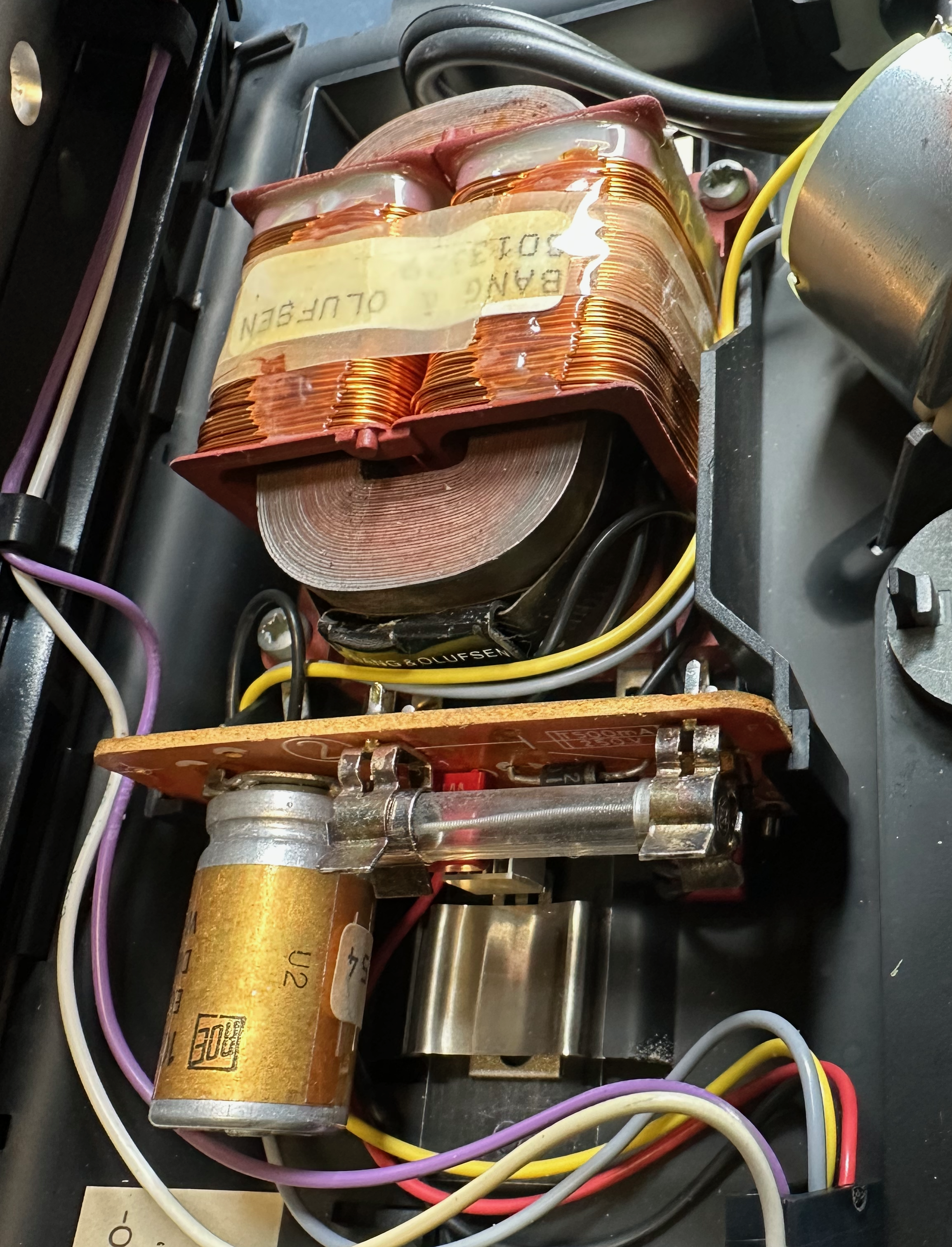
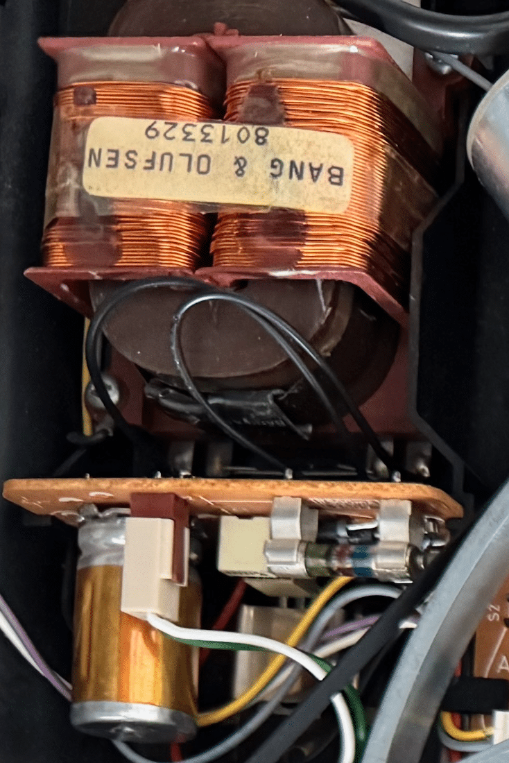
Of the US-based TX-2 that I’ve seen, it appears that both early and late examples utilized the power supply setup as seen below, irrespective of which generation main PCB was installed. This supply was wired for 120V, with a large fuse taking up much of the PCB #2 real estate, and no support for an RIAA hookup:
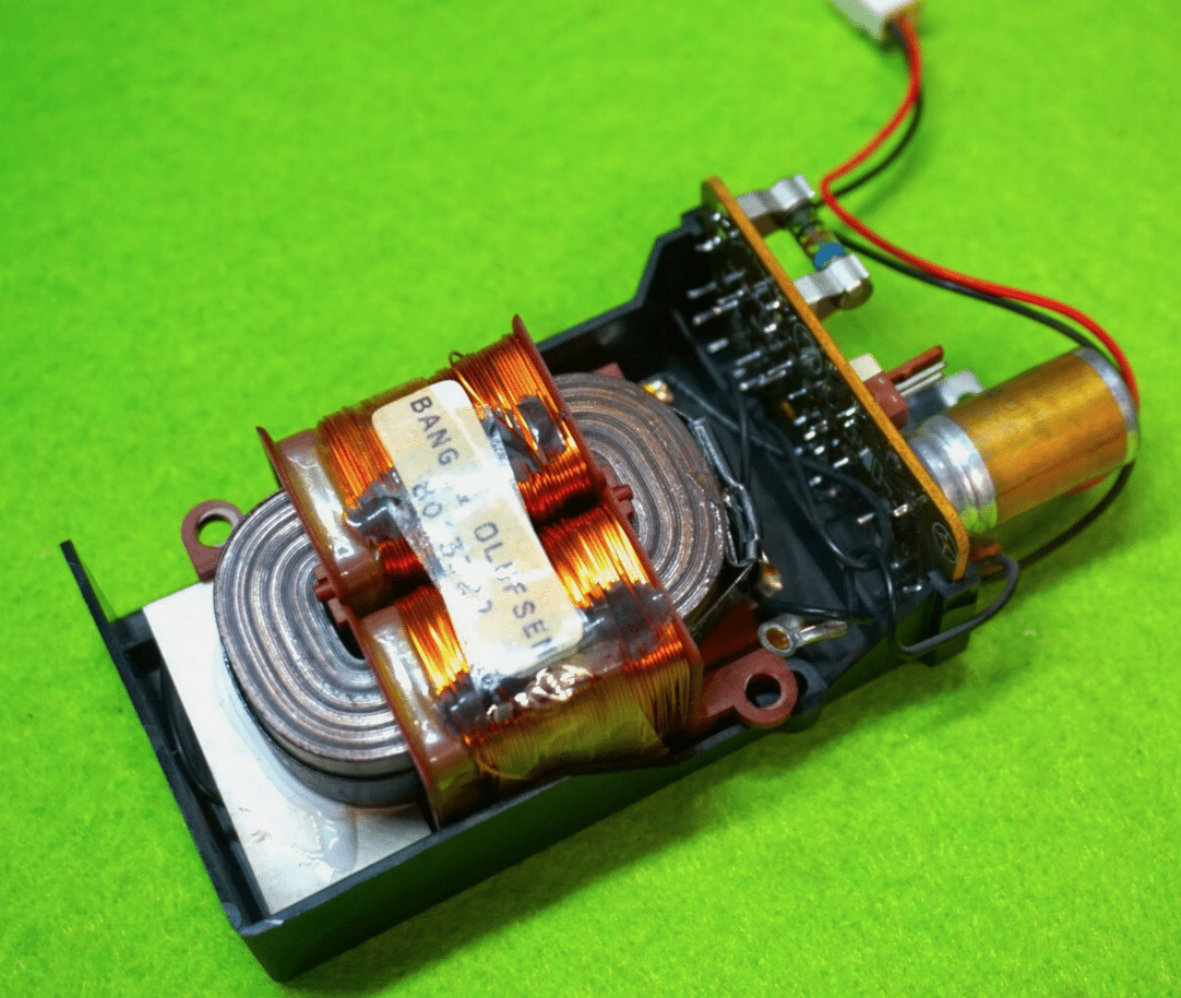
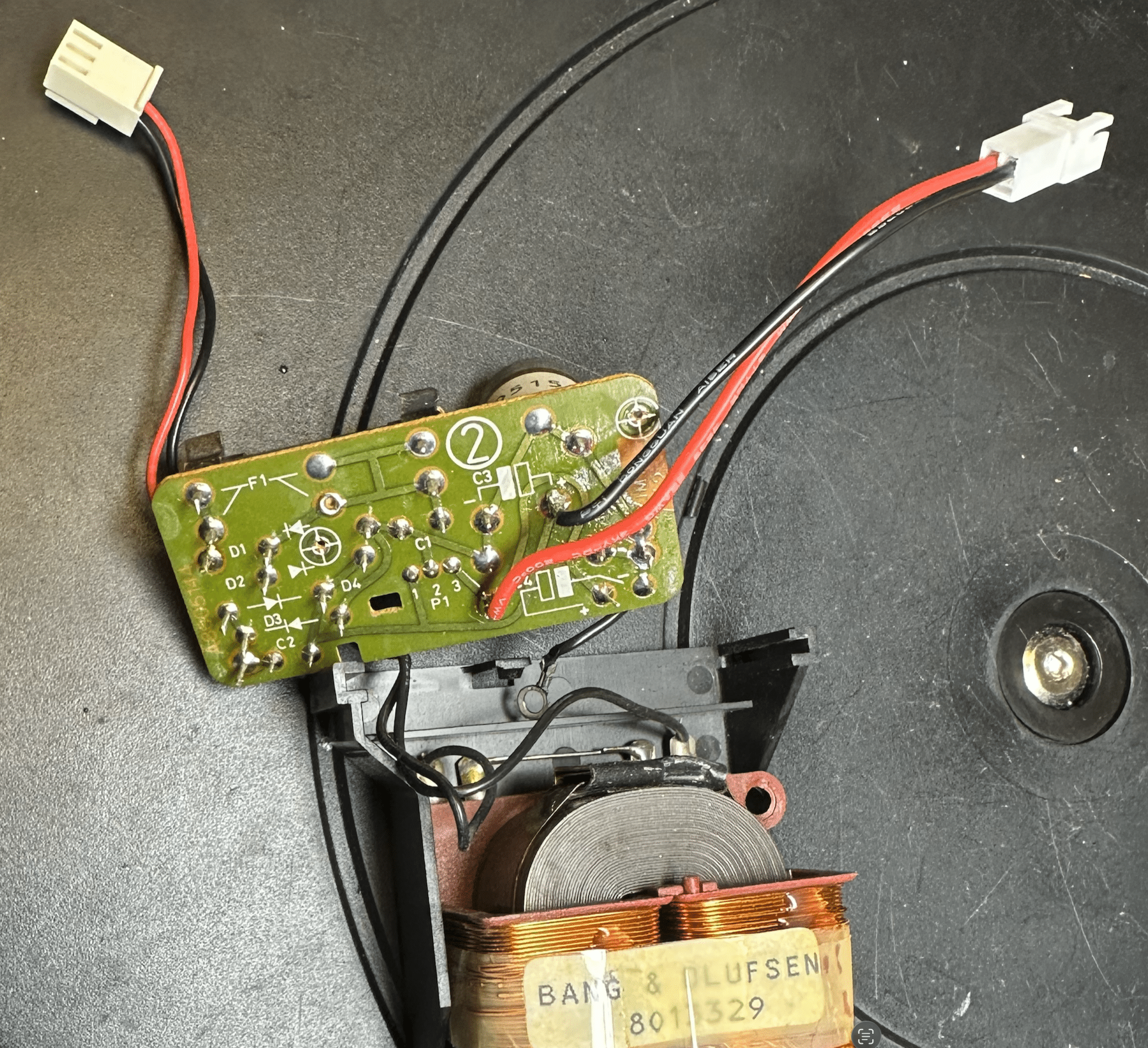
Later Euro TX-2 examples appear to have the 2-pin RIAA hookup, as shown here (photo 1 supplied by adyan, who has extensive knowledge on RIAA for these systems, and has supplied me with a pair of boards for this upgrade)
Here is a picture of a BG 6500 PS, which resembles the example that adyan has in his late TX-2, and also has the 2-pin power hookup.:
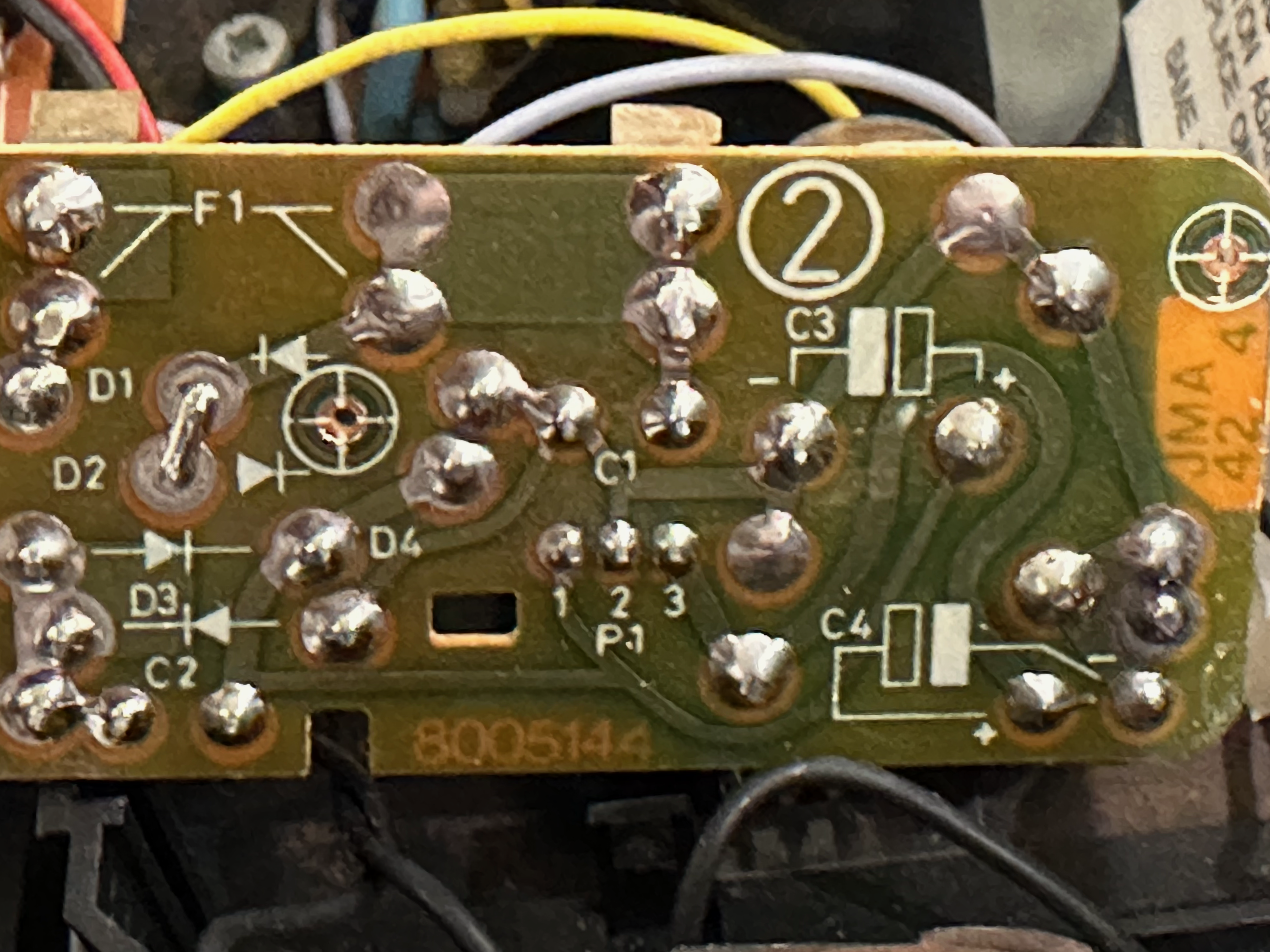
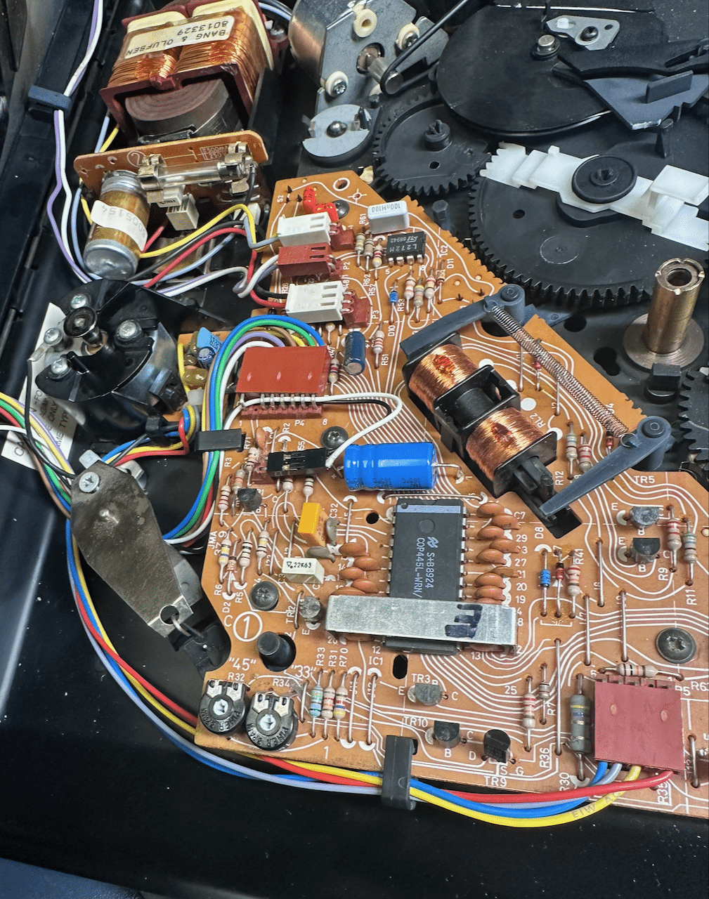
These 2-pin RIAA hookups draw from power points which are readily accessible from any of the TX-2/5500 ps, but it does require a bit of retrofit work to tap into them. My plan is to solder a plug onto the board that will allow access to the same power that the boards with built-in RIAA hookups have. On the board below, soldering a hookup to the bus leading to pins labelled 1 and 3 (center of board) of the IC I/O will give the needed result of having a 22V and 12V supply, respectively.
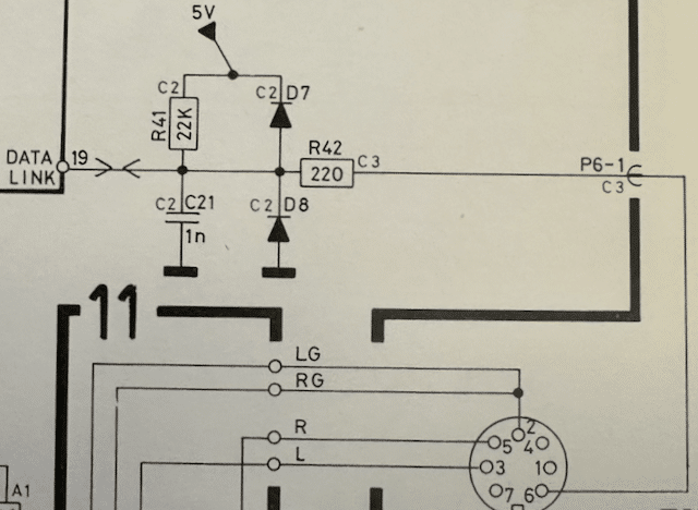
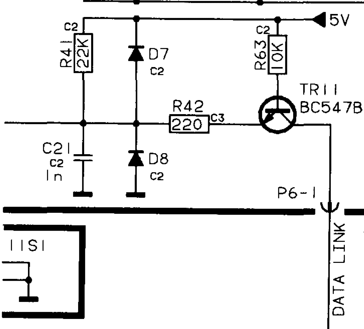
8 March 2026 at 05:33 #76041TKBRONZE MemberHere’s a “Old vs. New” 59XX schematic connecting the CPU to the Datalink bus. The new schematic includes a 547 transistor and 10K resistor hardwired to 5V, so it will be active as soon as the Beogram is plugged into power.
OLD SCHEMATIC
NEW SCHEMATIC
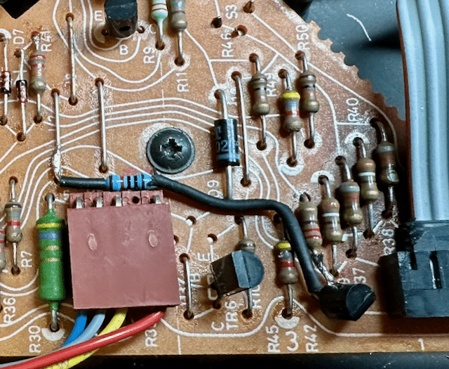
It turned out to be a fairly straightforward process adding a transistor to PCB1. I took a 547 equivalent transistor, and soldered a 10K resistor to the B pin, and added a bit of heat shrink to prevent a short. Next, I repositioned R42 by removing the Datalink bus leg from the board, and soldering it to the C pin of TR11. Last, I placed the TR11 E pin into the now-empty hole which previously connected R42 to the Datalink bus, completing the circuit. I contemplated drilling holes in the board and routing the wire underneath the board, but in the end my eventual solution was much simpler to execute, and I think it turned out looking OK – the parts are basically in the same spot they would appear in a later board, so it will be simple enough to understand what the retrofit’s purpose is. This is a picture from a 5005 board I had retrofitted earlier:
8 March 2026 at 05:53 #76047TKBRONZE MemberNext step is adding a power plug for the RIAA amps I purchased from adyan. His design mimics the original RIAA boards used in the 6500-7000 models, and therefore also needs a 22V and 12V supply, which it gets from the transformer on a plug from PCB2. None of my US-Spec TX2 transformers – early or late models – have this 2-pin plug, so I had to tap into the PCB at the correct spots. Here again I contemplated drilling PCB2 to add a surface-mount plug. And once again, for simplicity I opted to add a pre-wired 2-pin connector instead. I attached the red wire lead to the existing 12V wire hookup (post IC), and the black wire lead to the 25V output from the rectifier. This way, Red would consistently be the 12V supply. The plugs are male/female, so there’s no way anyone could accidentally feed a 25V input to PCB1 ground by mistakingly hooking up the incorrect plug.
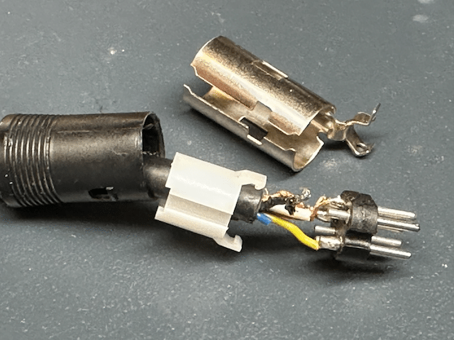
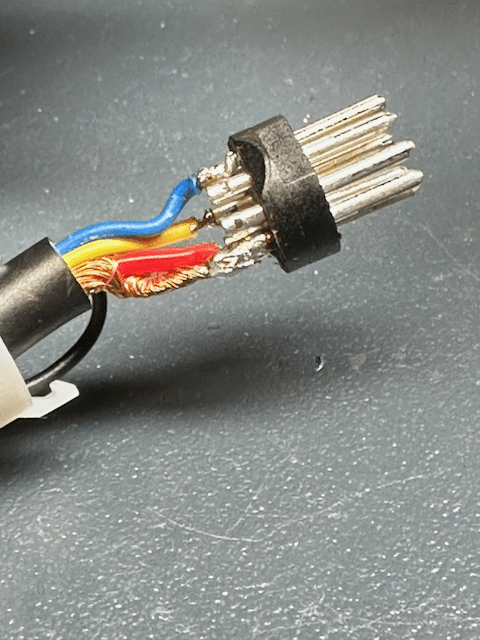
With these straightforward updates completed, I’m ready to tackle installing the RIAA board. I’ve opted to upgrade my 5500 and TX-2 simultaneously, in order to teach myself a bit about both upgrade paths.13 March 2026 at 01:27 #77359TKBRONZE MemberI decided I’d upgrade the 5500 first, on the thought that the wiring would be a bit easier. This proved to not be the case – B&O supplied the original output cable with an extra unattached blue wire, which was not connected to pin 7. I made the decision to disassemble the Din connector to attach it. This is strictly not necessary for my planned use, but I wanted to observe the convention that “Beograms with RIAA run Datalink on Pin 7”.
Upon disassembly, I found that not only was the blue wire not attached, it was truncated to the point where I’d have to un-solder all the pins and re-cut them to the new length. This is fiddly work which I’m personally not terribly fond of. I just happen to appreciate the coolness of a removable pin 6 and 7, and want to preserve that feature. I wired up both pin 6 and 7 with the blue and yellow wire. Without thinking about it first, I moved the yellow wire to pin 7, and soldered the blue wire to pin 6. Inside the turntable I’ll have the blue wire available on pin 6 for a future new project I’m dreaming about.
After a bit of squinting, cursing, and double checking my work for shorts, I was ready to reassemble the connector. Then came the “one-way” step of snipping the cable at a point I thought would provide enough wire on either side of the RIAA card to connect everything together using the original wires.
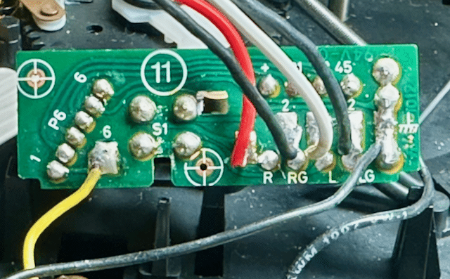
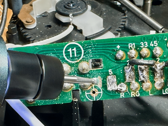
13 March 2026 at 03:02 #77370TKBRONZE MemberOn reading, re-reading, and re-re-reading the latest version of the service manual RIAA schematic, I came to the conclusion that the “Old Version” PCB 11 would need a modification in order to electrically emulate the “New Version” mute circuit. The original PCB11 is wired such that LG and RG from the stylus are not connected to chassis ground or shield ground until the wiring reaches the Beomaster. Further, the mute circuit is implemented by grounding the L and R to LG.
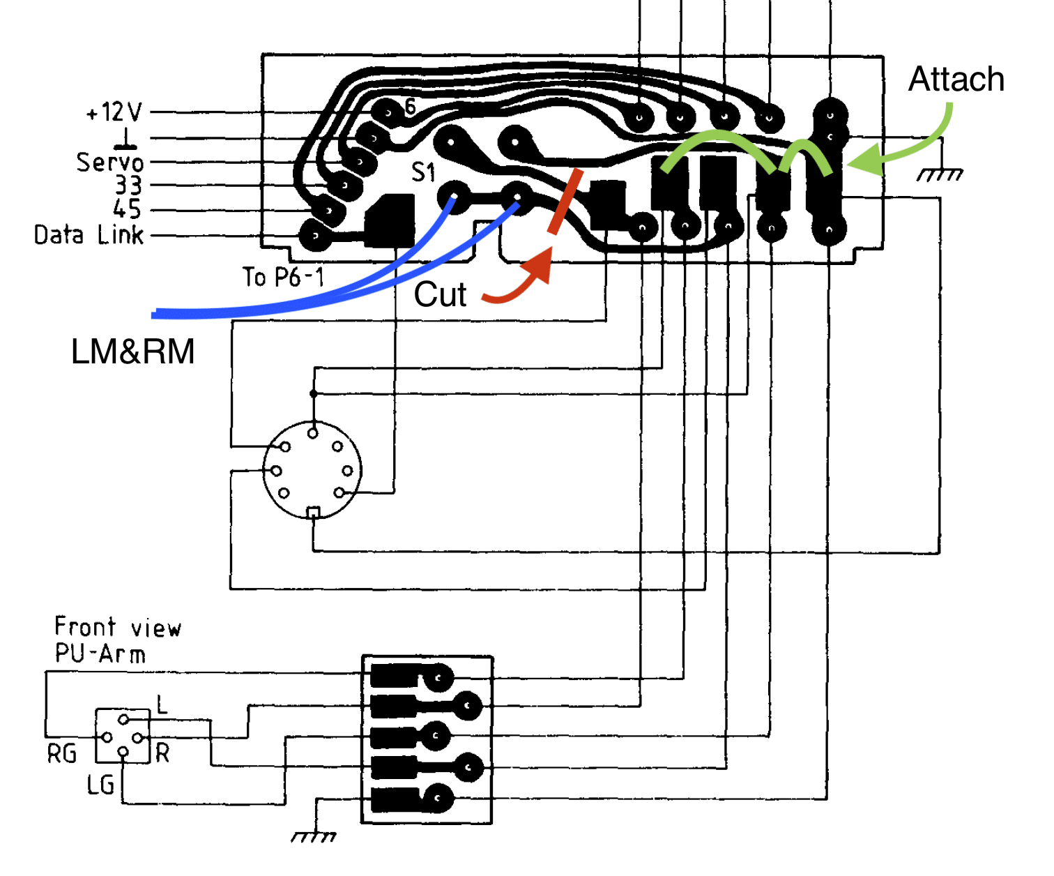
New boards designed for dual use as RIAA or non-RIAA implement a sightly different protocol, which necessitates the cutting of a wire bridge between some of the solder pads to achieve the desired circuit. Also, the LM and RM wires work a bit in “reverse”, where the mute circuit acts to ground the amplified signal on mute activation, before it reaches the output cable. The only way I could see to mimic this implementation was to grind a cut on the PCB itself, isolating L and R from the original mute circuit. [EDIT – I’ve made a small change to the schematic, and included both versions for comparison]
Original Version combines L+ R during ‘unmute’ – potentially undesirable:
Final Version – isolates L&R outputs during ‘unmute’:
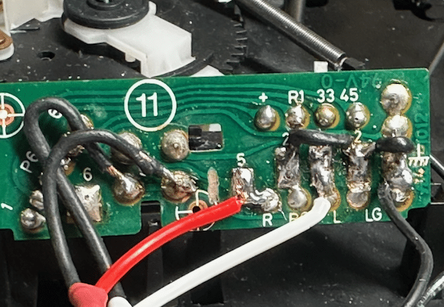
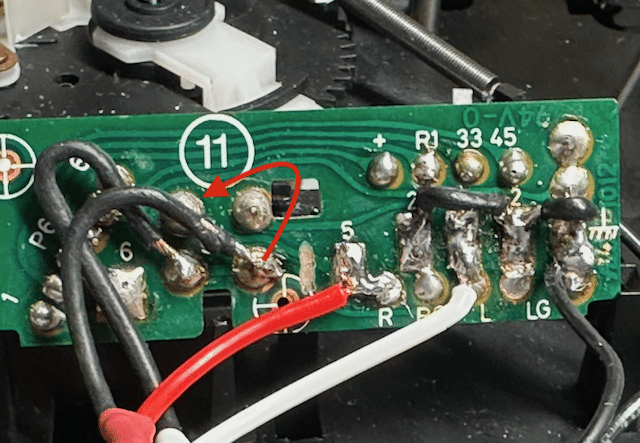
With that mental hurdle cleared, all that remained was to wire PCB11 with a jumper between LG, RG, and chassis ground, which meant that the mute circuit was now also connected to chassis ground. I considered that LM and RM are really the same signal and could actually just be activated together using a single wire [EDIT – I’m not actually sure this is 100% true in all scenarios, although it did appear to function correctly], but I went ahead and wired a separate LM and RM to the mute switch, per the schematic. [EDIT – even though the Original Version worked as wired, I realized later that I’d connected L+R in a way that might lead to some odd behavior when unmuted, so I moved one of the channels to a new position, where they would be isolated during ‘unmute’. The original wiring solution didn’t seen to affect the performance of the circuit, but the final version is representative of the original schematic] With L & R inputs reattached in their original spot, I was set to finish wiring up the RIAA.Original Version:
Final version:
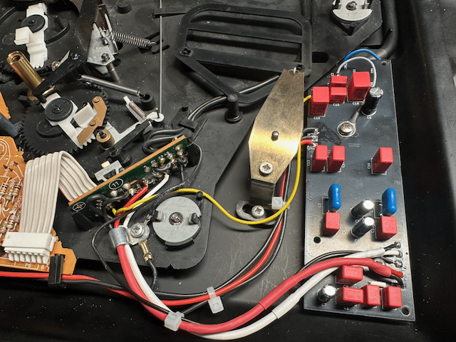
Admittedly sloppy, but it all toned out properly, so I left it as-is, and re-installed PCB11.13 March 2026 at 03:15 #77374TKBRONZE MemberOn to the final steps – finish routing the wiring, and connecting the RIAA. The original wires ended up being just a bit short to wire around the underside of the board as I would have liked, but at this point I didn’t care – I wanted to see if my upgrade had worked!
With the wiring complete, I re-calibrated the board based on the service manual (recall, I had swapped out the original 5500 board with a later board that had a discrete “Play/Off” feature, like the Beogram 7000).Moment of truth! Triple check to make sure everything was as-planned, and hook it up to my Beomaster 7000. Everything worked as expected – Lovely! Special thanks to @adyan for making a few RIAA boards for this project. I have no doubt the TX-2 will work as well, but I’ll go through the steps to document the process.
13 March 2026 at 05:52 #77399adyanBRONZE MemberCongratulation, glad that everything worked out and have a nice time listening to your upgraded beogram.
15 March 2026 at 06:35 #79394TKBRONZE MemberI took delivery of another late-model PCB1 control board (with the discreet Play/Off hookup), so I decided to replace PCB1 on my 5005, and do a bit more analysis of this late-model feature.
This additional feature basically provides continuity over the component range, as compared to the earlier Beograms where the button was a mere extension of the “Play/Repeat” button located inside of the cover. The original Datalink status sent by the original Beogram 5005 thru 5500 was “Play/Repeat” is a single Datalink command “Beogram.Status.Playing” when first pressed. Subsequent presses of the “Play” button put the Beogram in ‘Repeat’ mode, and were handled without sending any additional information back to the Beomaster. In fact, this was a missed opportunity by B&O to send a ‘Status.Counter’ to update to the MCP on any ‘Status’ request, showing the number of queued repeats – for example, the Beogram could easily have been coded to send “Beogram.Status.Counter ‘C 03’ “, reporting back to the MCP screen the number of record plays remaining – a trivial code addition which could have provided some visual feedback to the listener as to the number of repeats remaining.
Conversely on the late PCB1 board, the pressing of the front button while the Beogram is playing sends two Datalink commands: “Beogram.Status.Standby”, followed a few seconds later by “Beogram.Status.Stopped” when the platter stops spinning. Sending the Standby command will cause the Beomaster to act accordingly.
If I ever find the time to create a replacement microcontroller for the Beogram, I’d like to add a feature-set which provides more status reporting to the listener. Repeats, song count (based on 3 seconds of silence, for example), 33/45 selection via the MCP, and things of this nature would make excellent upgrades to the base system.
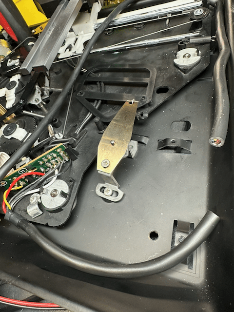
15 March 2026 at 06:57 #79399TKBRONZE MemberJust to document the needed changes to add discreet “Play/Off” function to an early Beogram, these are the steps.
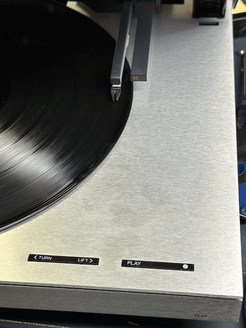
The “Play” button is fixed in place with a black bracket, which holds the button in the appropriate place on the front panel.
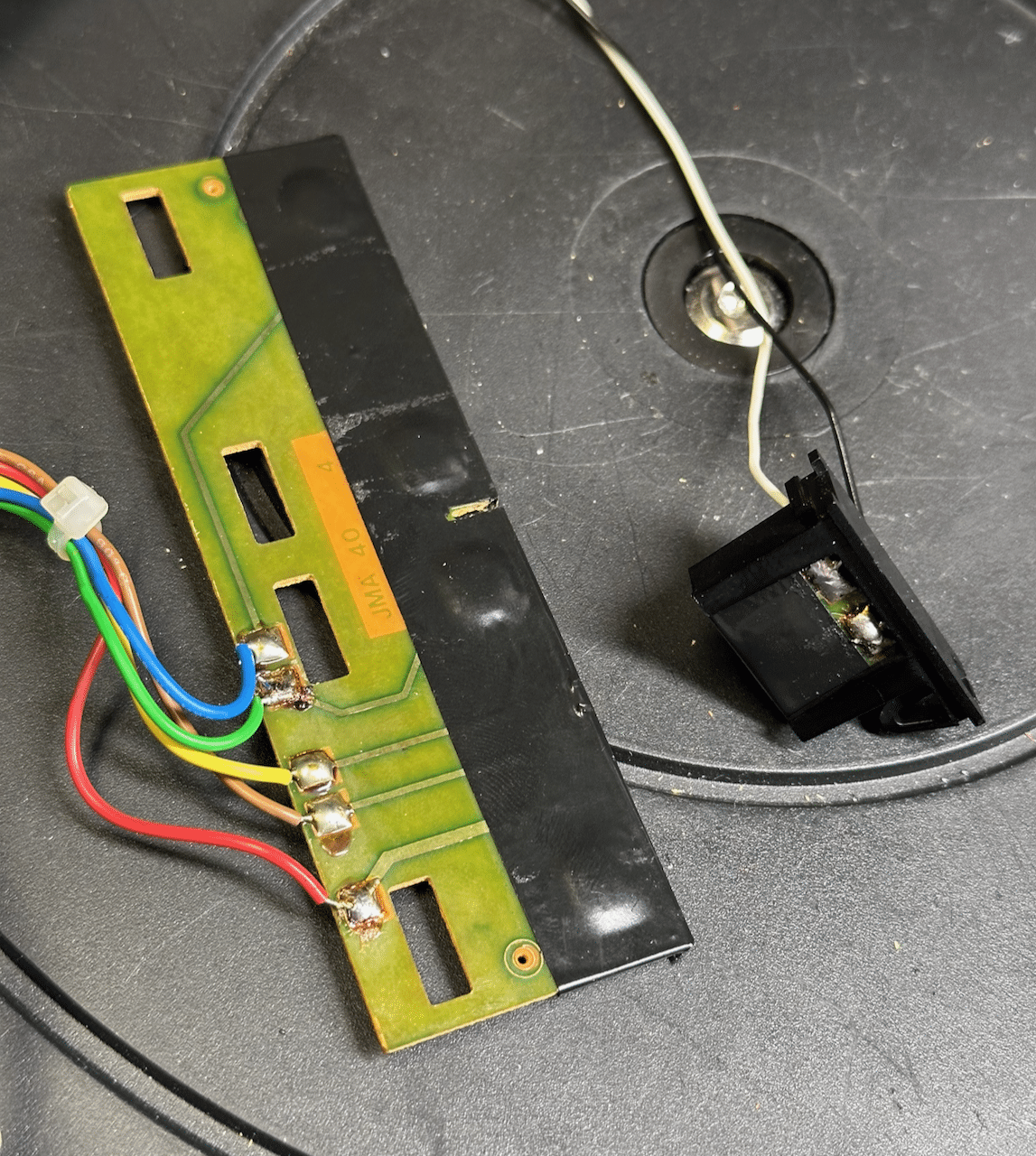
It’s wired directly to the “Play” button on the top surface, so it only can perform the same function as the “Play” button under the cover. The large PCB3 is removed by carefully moving the 4 black tabs that hold it firmly in place, and wiggling the PCB up and back out of its mount.
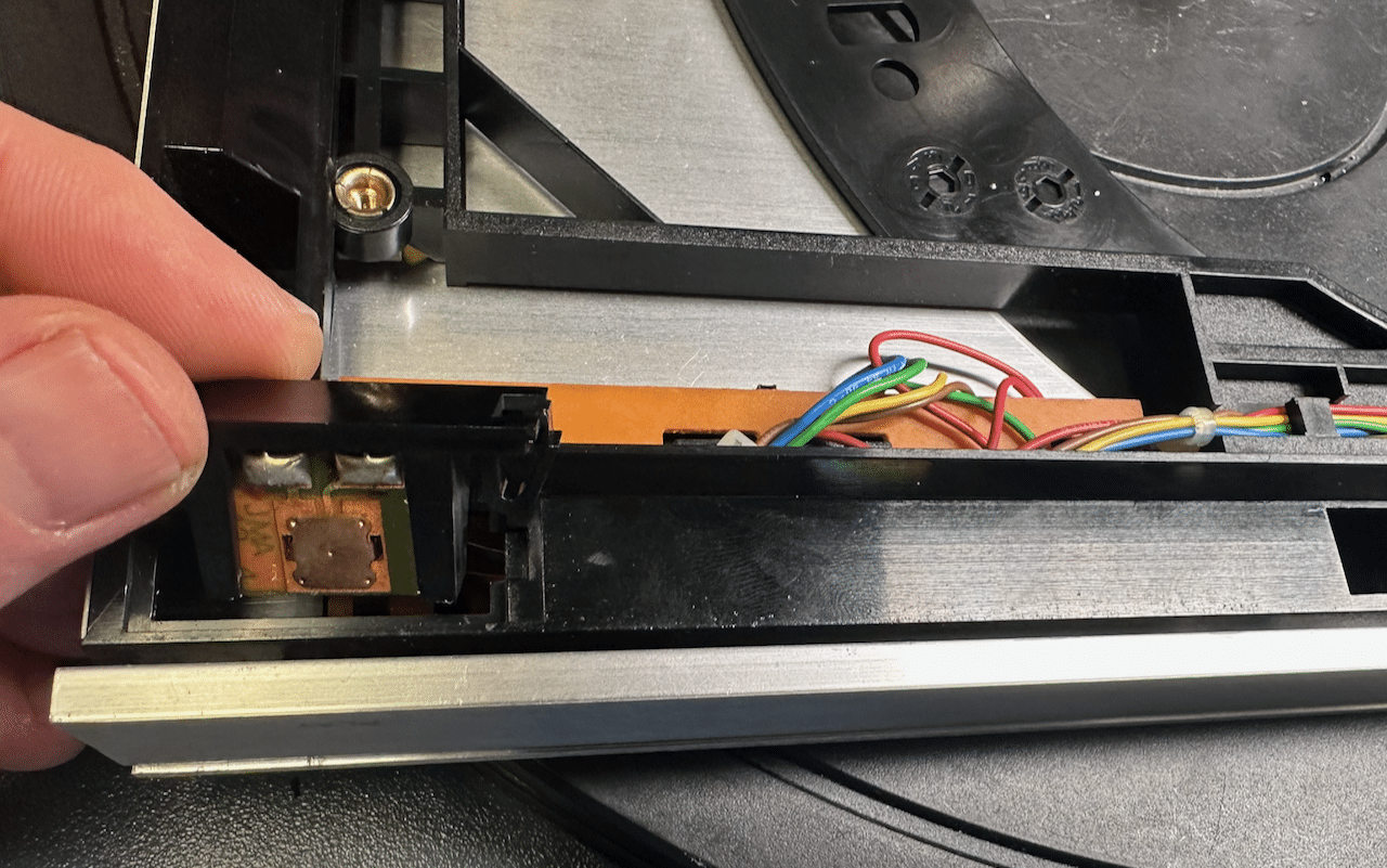
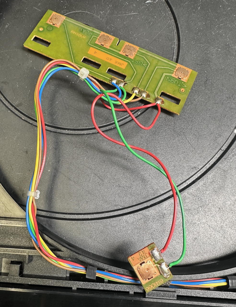
I was surprised to see that these buttons were exposed – typically, they are covered with black tape to help hold them in place (and probably also to keep moisture and debris out from them – they are a slightly cheap design, and can easily be made inoperable with a bit of contaminant). I fixed the vulnerability by adding a bit of electricians tape myself. Next, I severed the connections of the small PCB, and added two additional wires to it, per the new design specification.
Last, I ran these new wires back through the cover, using the same clamps used for the existing wires. A bit of trimming later, and everything was hooked up per the late-model specifications. A fairly straightforward modification.
I’ve elected to not add an RIAA to this unit, as I need something I can use to test with earlier variants of Beomasters with built-in RIAA. So this unit is upgraded as much as it can be, and ready for work. -
AuthorPosts

- You must be logged in to reply to this topic.