


Home › Forums › Product Discussion & Questions › BeoVision › Summer Project – Beovision MX5500
- This topic has 19 replies, 7 voices, and was last updated 2 years, 5 months ago by
 RallyMK1.
-
AuthorPosts
-
14 June 2022 at 06:51 #35478RallyMK1BRONZE Member
Hi everybody!
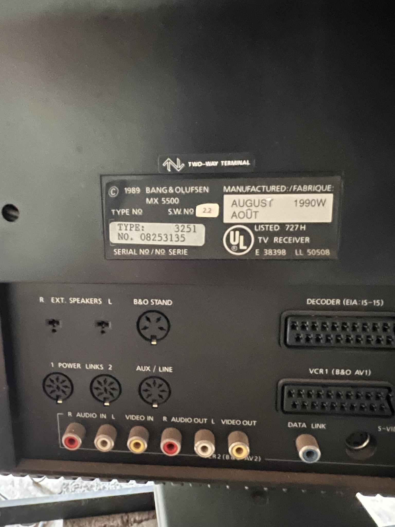
Just a few weeks ago, came across a Craigslist ad here in California for a B&O MX5500, including the motorized stand and the VCR for $500. I’m really into vintage TVs and retro gaming, so when I saw the ad I was definitely excited. My console RCA had just failed, and I was looking for an interesting replacement.
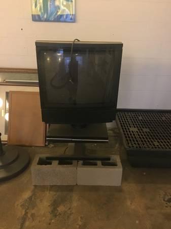
When I came to check it out, I found that it had been stored in a landscaping company’s shed for the past 15 years. We couldn’t get it to power on, and the remote was missing, so the seller gave it to me for free.
I got it home in one piece, cleaned it up, and found that I could get it into standby mode with the power button in the front, but the step button did nothing.

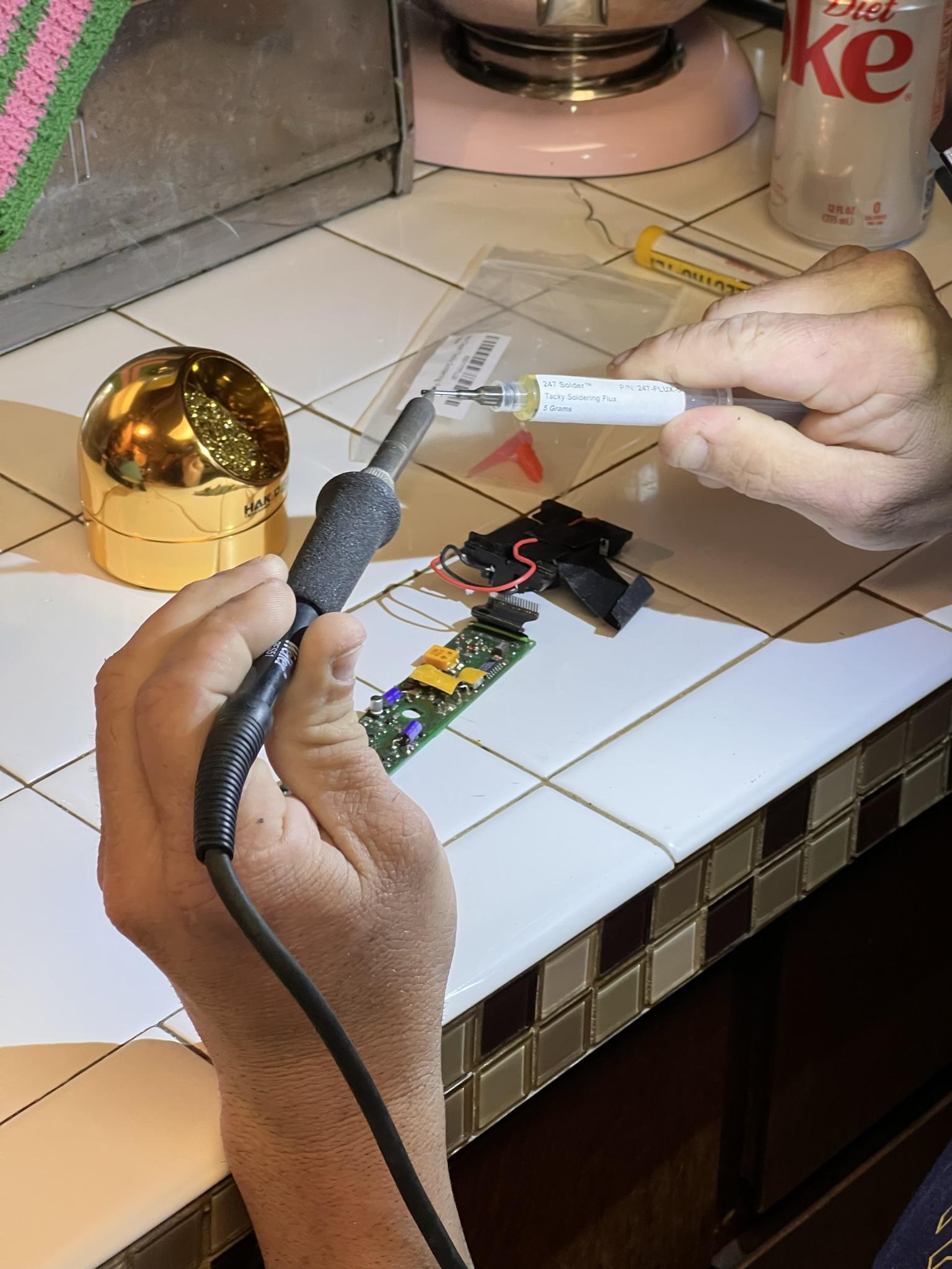
So, it sat in the spare room, waiting for a remote. I found a Beolink 5000 for dirt cheap, sold as not working, and that arrived just yesterday.
Of course, it came in pieces, but after soldering the battery compartment back together and cleaning the contacts, we got it to output a signal! Hitting the TV button caused the TV to turn off immediately. The next step is opening up the system, and starting with the power supply, testing and replacing components.
It’s in pretty decent shape, so hopefully I won’t need to replace every single cap. I’ll document the progress, and hopefully, add some interesting information into the public record to help out anyone else trying to get their 32 year old TV working again.
15 June 2022 at 15:50 #35479 Die_BogenerBRONZE Member
Interesting project 🙂
This is a US MX5500?
The European modell is complete different.
 15 June 2022 at 16:09 #35480RallyMK1BRONZE Member
Oh wow, that is totally different. Yes, it’s the US model.
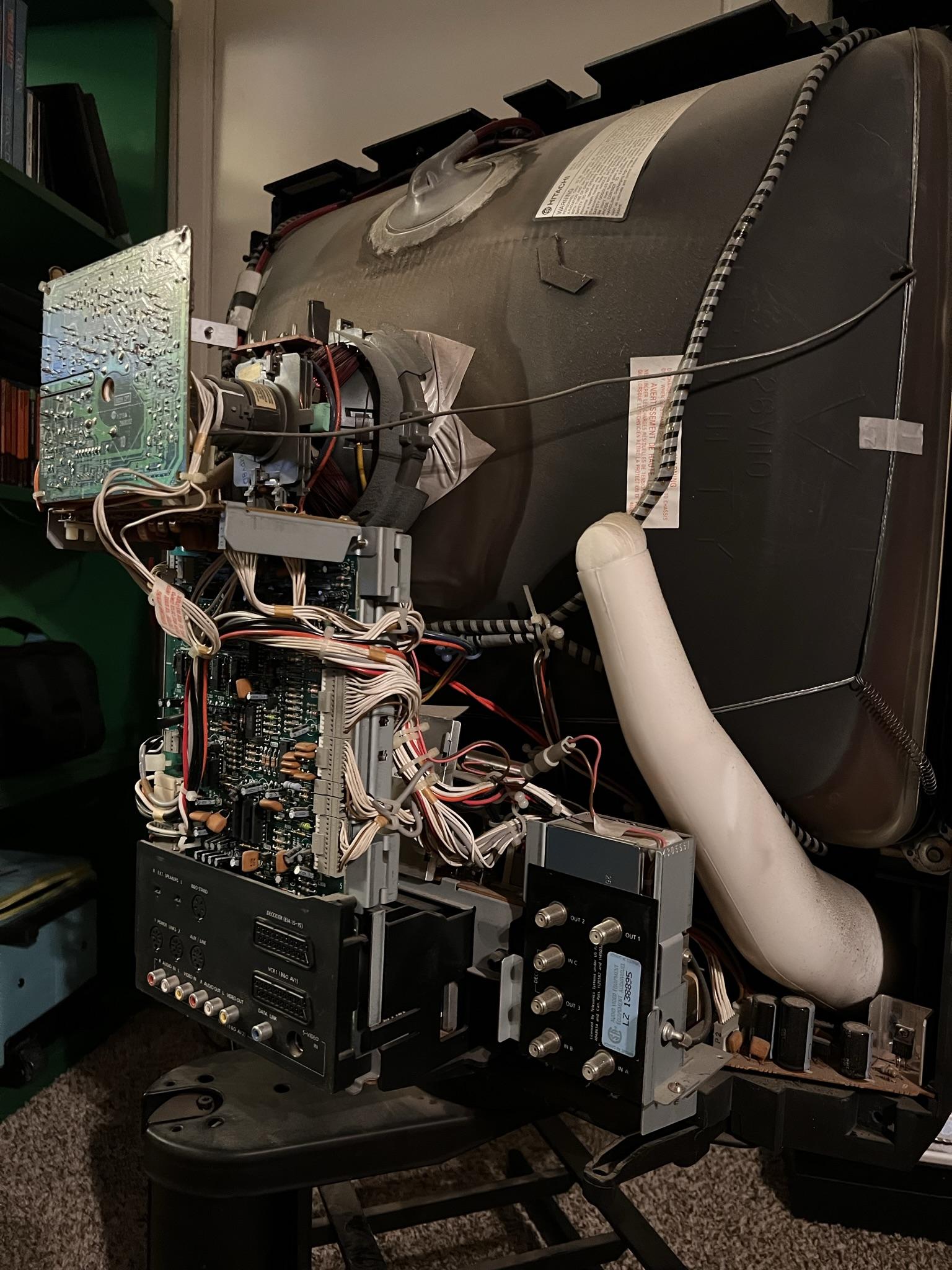
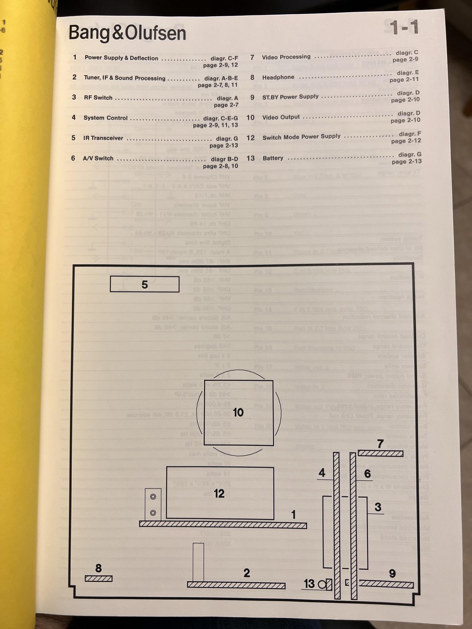
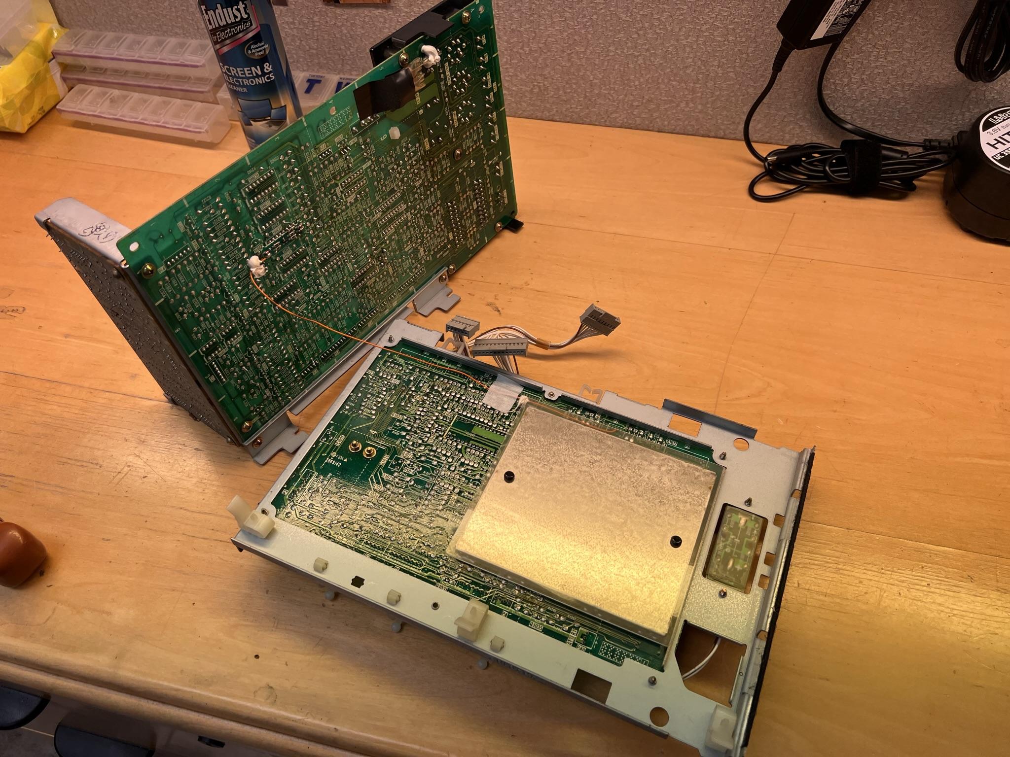
22 June 2022 at 18:53 #35481RallyMK1BRONZE MemberYesterday’s project was removing all the individual boards for full capacitor inspection. The service manual shows all the boards in this map, and to make it make sense, they have swung out the boards shown on the right as they are all connected together on a rail that unclips from the back.
The only tricky part in removing the boards was that PCB 2 has an RF cable soldered to its connection, so you just need to heat it gently and pull it off with some needle nose pliers. The rest are just connected by an incredible hydra of wiring, but thankfully, each connector is labeled with the port it connects to, so as long as you go in order, reassembly shouldn’t be too difficult.
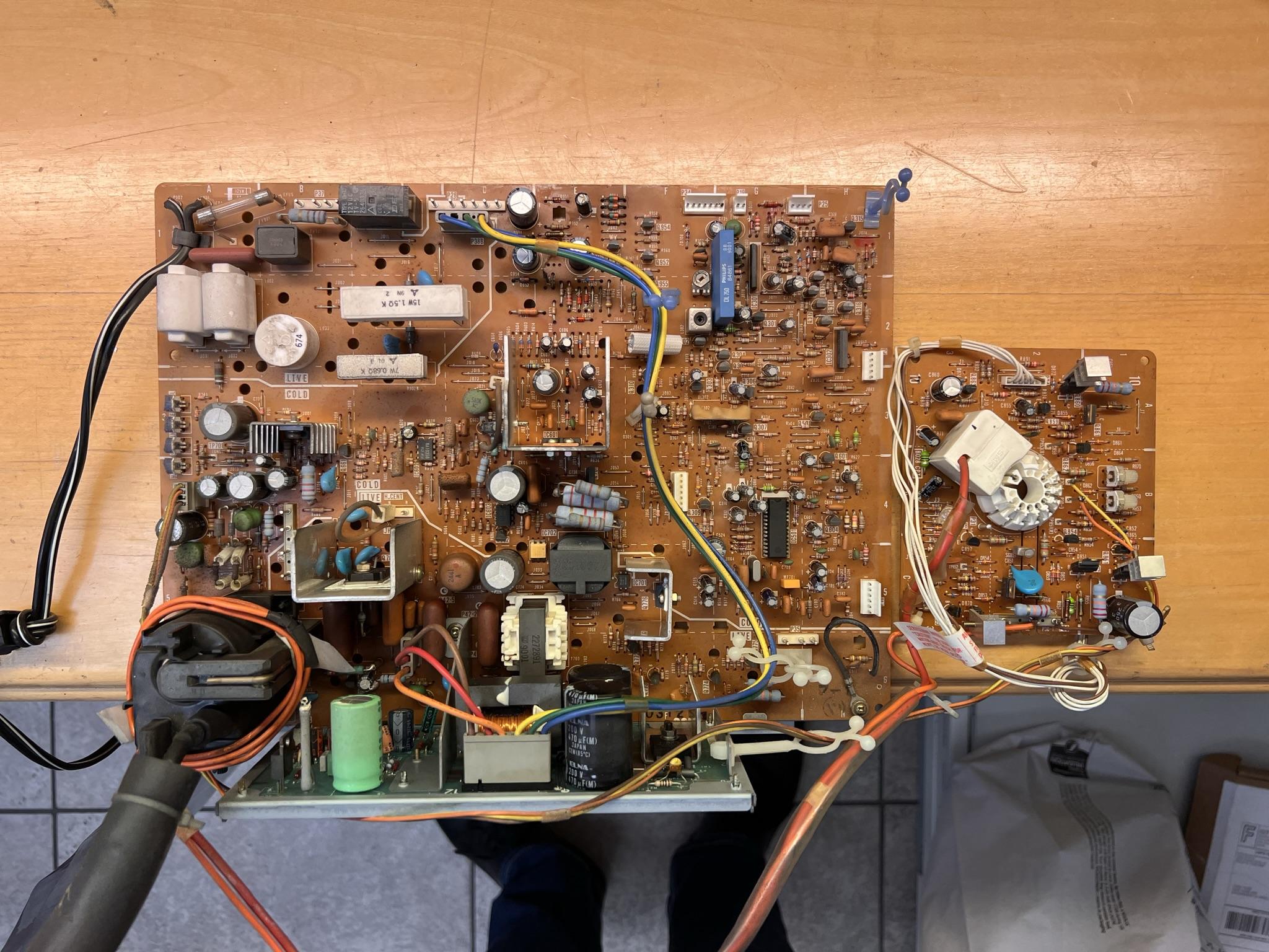
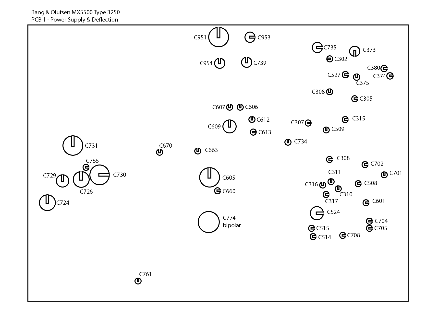
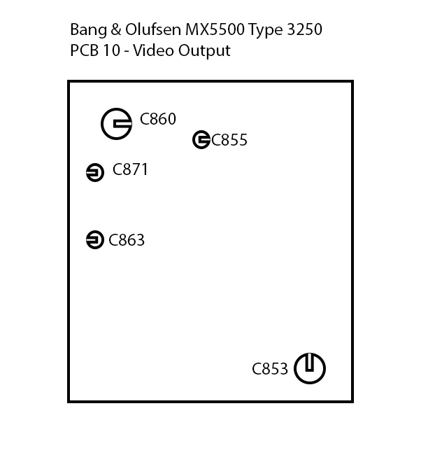
PCB 1 – Power Supply and Deflection

This pic actually shows PCB 1 – the main board, PCB 12 – Switch mode power supply, and PCB 10 – Video Output, as they are all interconnected. When I removed the Anode cap, I got no spark at all from a grounded screwdriver, so it’s likely that we aren’t getting power to the flyback at all. The main fuse is intact and shows continuity, and no obviously bad caps present themselves, so we may have a dead transistor or maybe even the flyback. The caps will all get replaced regardless, and then further testing can progress.
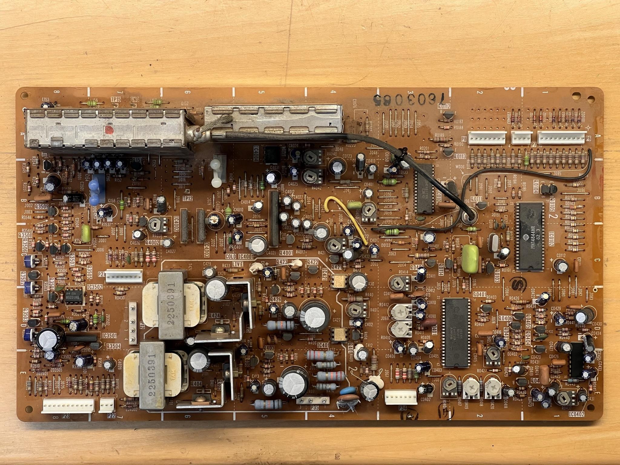
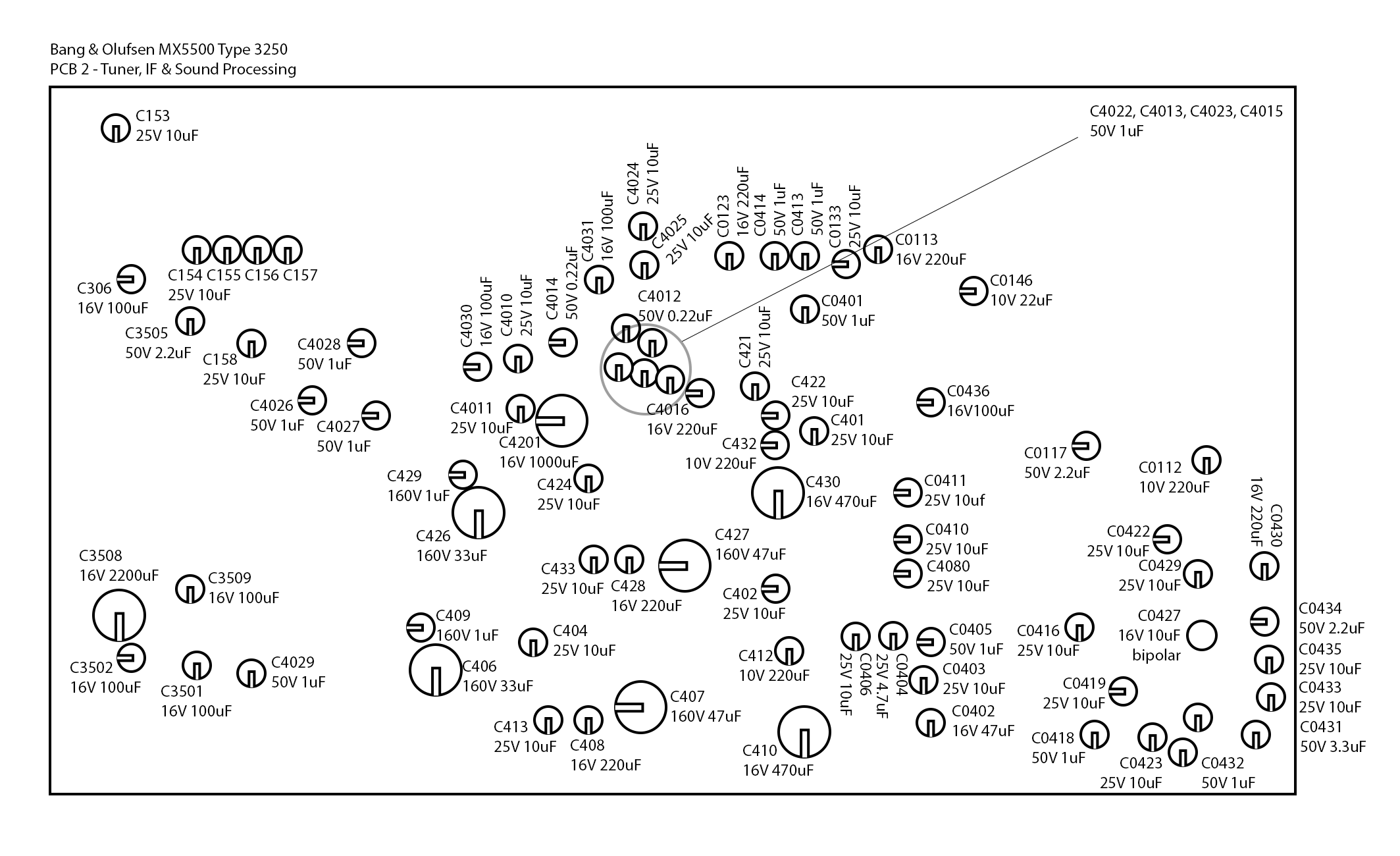
PCB 2 – Tuner, IF and Sound Processing
Here’s where I find the first obviously bad cap. C4030, in the middle above the two transformers has a rusty top.
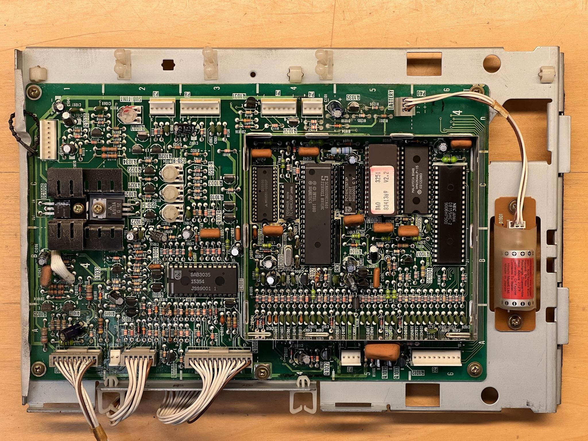
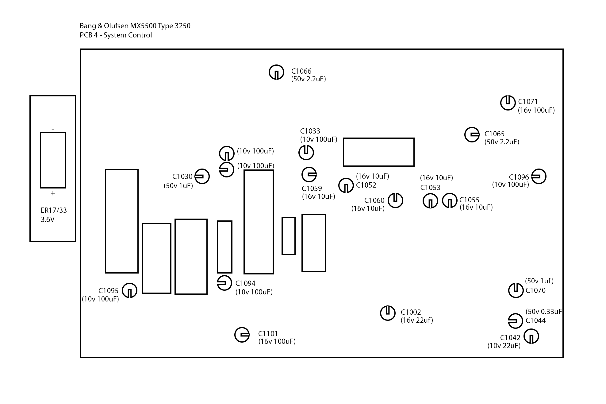
PCB 4 – System Control
PCB 4, 6 and 7 are all screwed and clipped together. There is an orange wire that goes between them that has to be desoldered.
System control contains the CPU, BIOS and the rest of the chipset, all connected to a 3.6V battery that miraculously is not dead and leaky, but also is still running at 3.3V! Quite a few bad caps in here, especially in the little processor village. On the opposite side of this board is a steel cover that has been soldered, so that will need to be desoldered to reach bottom of the board for the cap replacement.
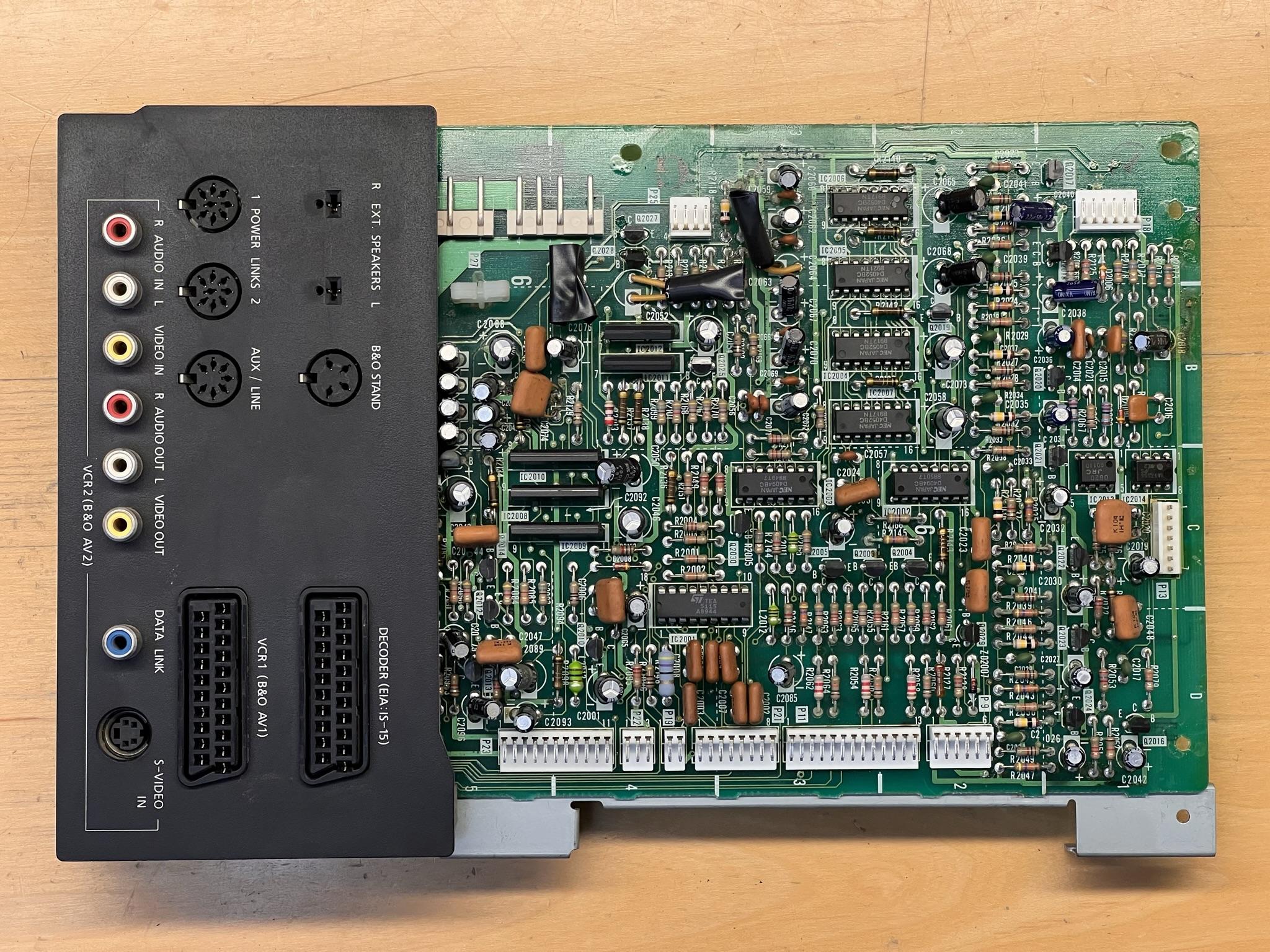
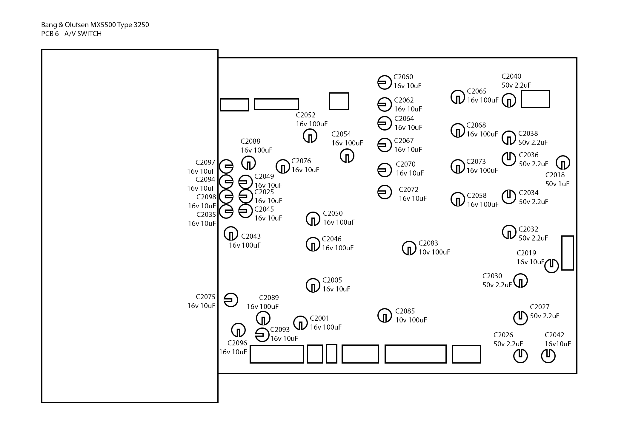
PCB 6 – AV Switch
The only thing to address on this one will be to make sure the discoloration at the top is not trace corrosion. If it is, some bodge wire will need to be run after the caps are replaced.
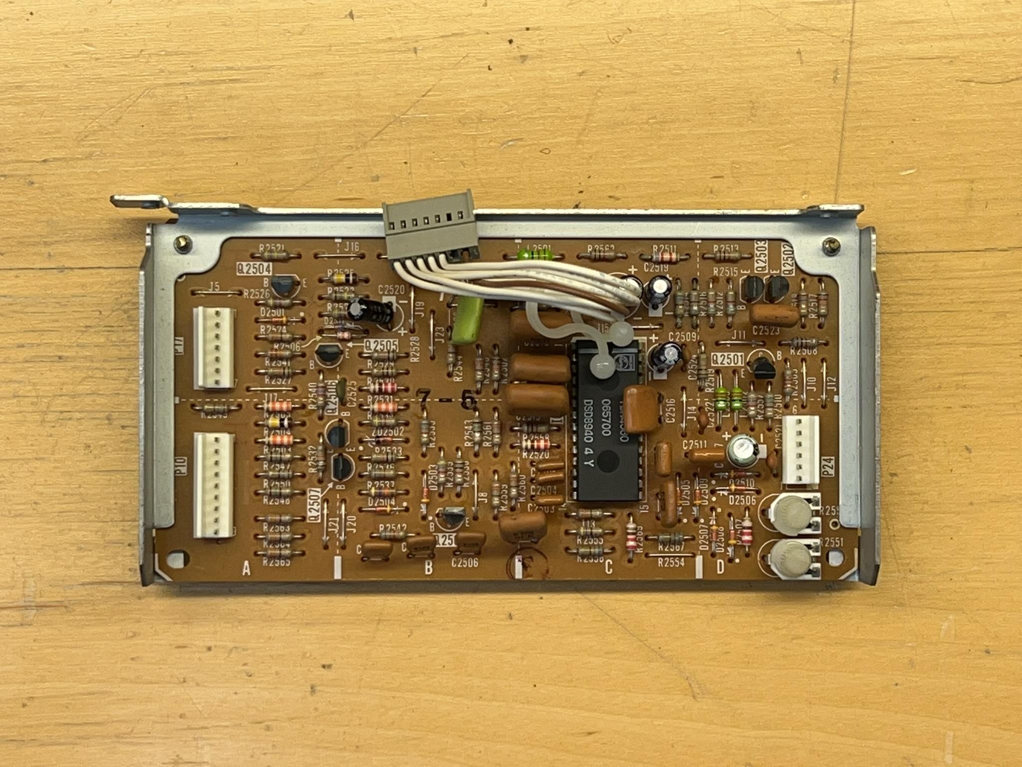
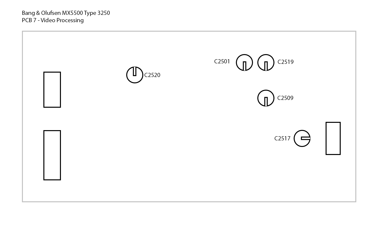
PCB 7 – Video Processing
This little guy attaches to the top of PCB 4 & 6, and only has a few caps.
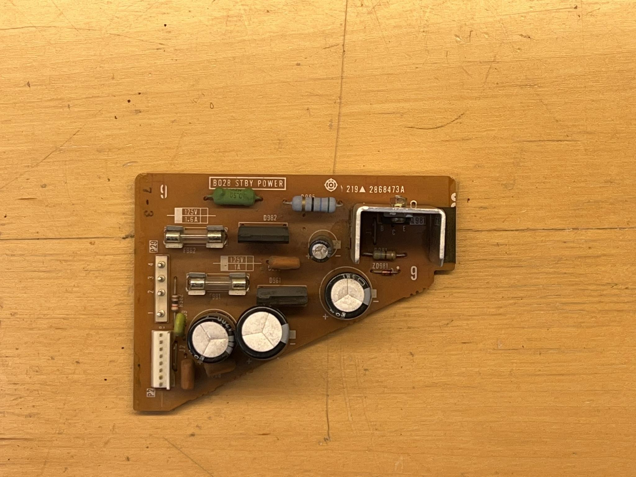
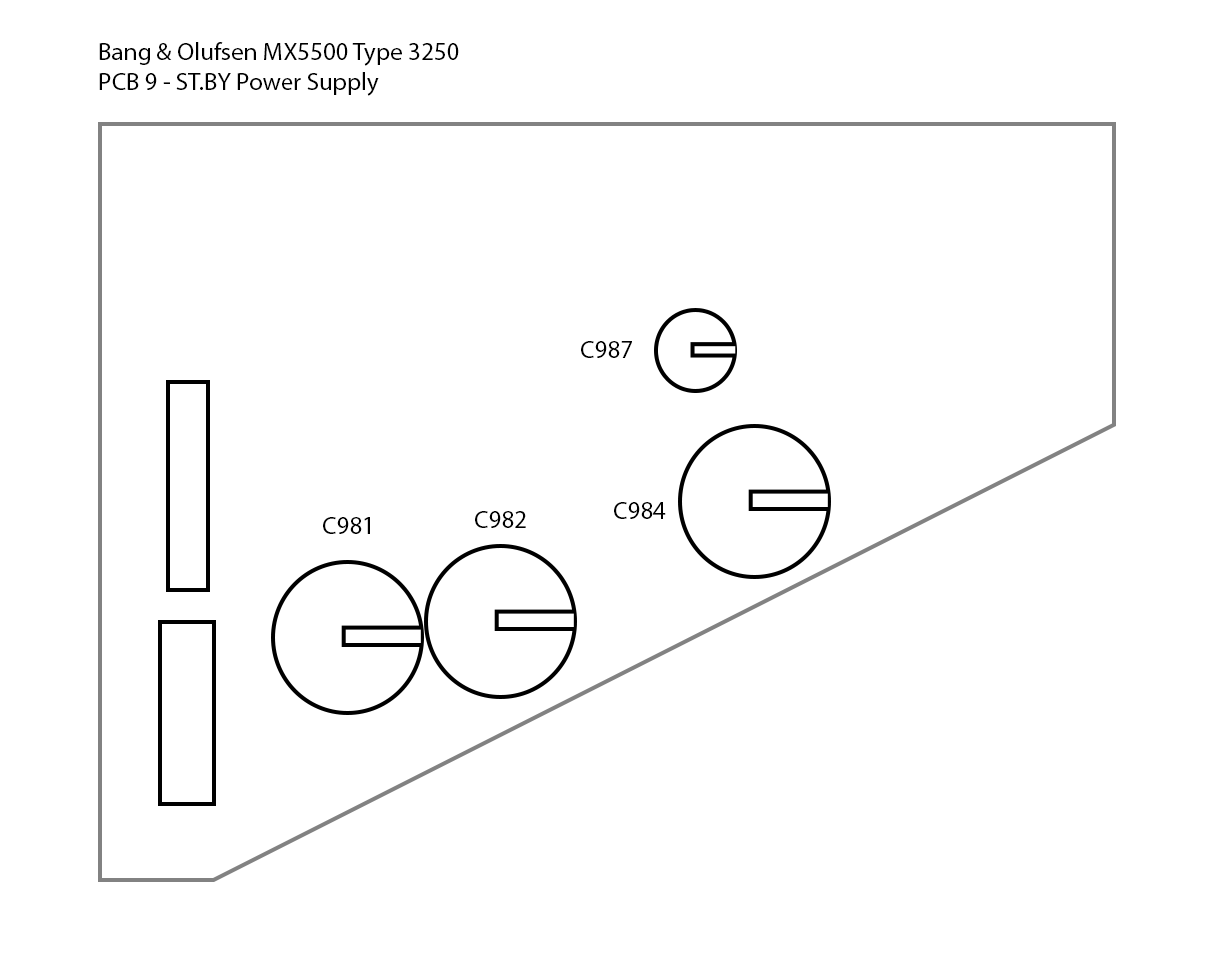
PCB 9 – Standby Power Supply
Because the TV turns on into standby mode, it’s assumed that this guy is fine. The fuses check out, and the transistor passes diags as well.
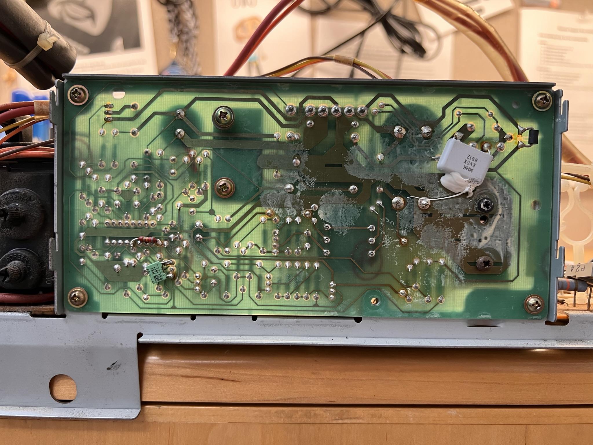
PCB 12 – Switch Mode Power Supply
This is the back of the PCB, attached to PCB 1.
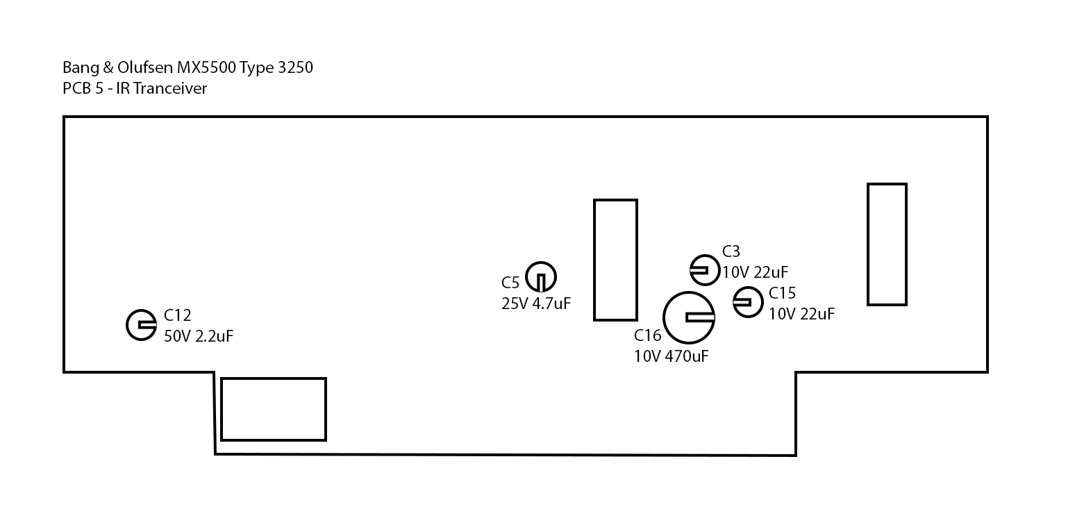
A few PCB pics were omitted, like the power and step button board, since there’s really nothing to it, but it was tested for continuity and confirmed working. I don’t have a pic of PCB 5 – IR Receiver, because I forgot it at home. Visually, it looks fine, and just has 3 caps.
The next step is to make a capacitor map based on the pics here, put an order in to mouser, and see where we’re at after that.
Coming soon will be scans of the American Service Manual and the regular manual, unless you guys have that stuff already.Also, if anyone has any advice or sees something I don’t see, by all means, please let me know. I’ve repaired a few arcade game PCBs and some old consoles, but there’s a lot here that I’m learning for the first time, so any tips would be appreciated.
28 June 2022 at 21:53 #35482RallyMK1BRONZE MemberFinally finished the cap map for all the PCBs. Caps have been ordered, and I’ll be able to get started replacing all these little guys next week. Here are the maps for your enjoyment.


Still working on scanning the service manuals. Will get those uploaded soon.
5 July 2022 at 02:50 #35483jvezinaGOLD MemberGood evening,
I owned a US MX 5000 (the previous model) for about 30 years. For the time, it had an excellent picture. Unfortunately, I damaged it when reassembling it by accidentally dropping a screwdriver on the case a few years ago. The picture tube shorted. It required another massive capacitor replacement, so it was not catastrophic.
In your case, the first thing is to replace all capacitors branded Rubycon. There may be 100 or more. You should also get an ESR meter to check all remaining ones. If the set was stored for 15 years, expect to see most of the capacitors dried.
On PCB 6 be very careful when removing capacitors. The black Rubycon caps leaks and damage the traces on the component side.
I have prepared a long time ago a repair guide for the MX 5000. It should be on the service manual section.
Capacitor replacement is also required for the VX 5000.
Good luck,
Jean
My B&O Icons:
5 July 2022 at 20:13 #35484RallyMK1BRONZE MemberI’m sorry that happened! It’s always frustrating when something fails due to a mistake. I’ve certainly had it happen to me before, and the lessons have been expensive 😉
Cap replacement is definitely job #1, and I get to start it today! Mouser delivered over the weekend, and the tedious process is already underway.
Thanks for the heads up regarding PCB 6. I can already see a lot of damage, and hopefully, I won’t make it worse in the process.
19 July 2022 at 00:22 #35485RallyMK1BRONZE MemberWell, all the boards have been completely recapped, but the TV isn’t springing to life yet.
It goes into standby mode, and I can turn it on, which makes the red light go out, but nothing shows up on screen. The step button doesn’t do anything, we can only turn it on with the remote.
We’re poking around, and will hopefully have an update in the coming weeks.19 July 2022 at 12:53 #35486Interesting project
This is a US MX5500? The European modell is complete different.
I love how both of these Beovisions have speaker outputs for connecting non-active units for stereo sound! Such a rarity in other tvs from this era.
Location: Kent, UK
Favourite Product: Beosystem 6500
My B&O Icons:
18 June 2023 at 21:57 #35487WesBRONZE MemberWell, all the boards have been completely recapped, but the TV isn’t springing to life yet. It goes into standby mode, and I can turn it on, which makes the red light go out, but nothing shows up on screen. The step button doesn’t do anything, we can only turn it on with the remote. We’re poking around, and will hopefully have an update in the coming weeks.
Please keep us posted about the progress. I have the same model mx5500 ntsc but when i try to use the scart port i just get a scrolling image and I cant figure out why.
By any change you know how to enter the service menu ? or theres info. of some sort about that in your user manual ? Thanks
3 October 2023 at 16:52 #35488ECK_DATABRONZE MemberHey! I just found the same MX5500 model and I am planning on doing a full recap soon. Any updates about your project? Were you able to save it?
*Thanks for the capacitor mapping by the way, this will be very useful! Did you save a ‘project’ on Mouser when you ordered?
3 October 2023 at 16:56 #35489RallyMK1BRONZE MemberGood luck! Sorry, mine still isn’t working. While I’ve made progress on a pile of other TVs with weird issues, I haven’t been as lucky with this one. If I ever find out what’s definitively wrong with it, and if there are any fixes, I’ll be sure to put anything I find out in here.
3 October 2023 at 17:40 #35490ECK_DATABRONZE MemberYeah i’m not expecting great result with this, but I do get an image to begin with so i thought I’d give it a shot! I’ll keep you posted on my progress 😉 Cheers!
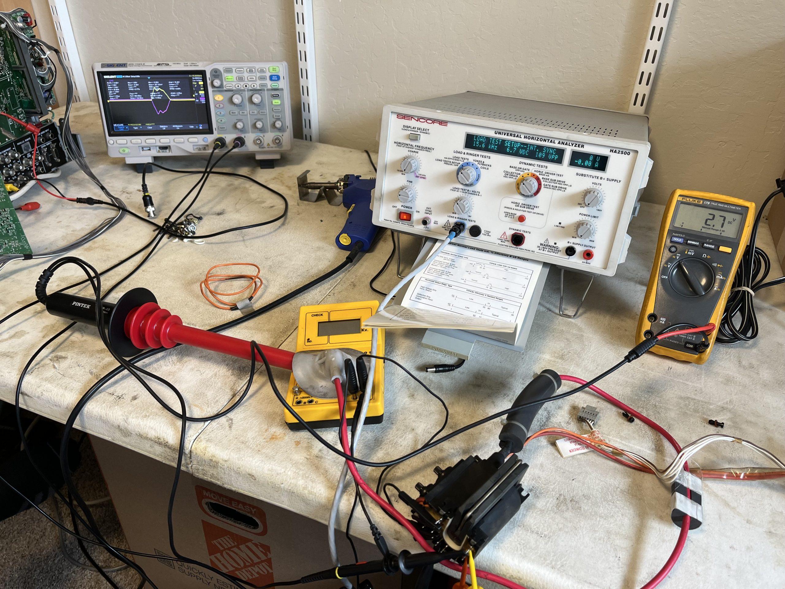
25 October 2023 at 13:48 #35491RallyMK1BRONZE MemberWell guys, I have an update today, and unfortunately, it looks like flyback failure. I was fortunate enough to have some friends in the Bay Area with another MX-5500 they were working on, and were willing to swap boards from mine for testing so I wouldn’t have to drive the whole TV down there.
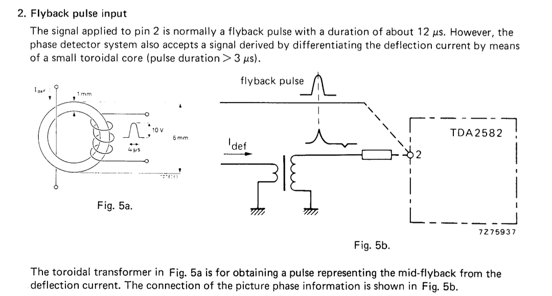
They were able to trace back the problem to the protection in the switching power supply: IC1 is a TDA2582 and all pins are on spec except pin2 that checks the flyback pulse for a duration of ~12us coming directly from the HOT (through a few caps and a resistor, no coils)
They tested the flyback and noticed that the pulse was very very short (2-3us). They thought it was because there was no yoke coil connected, but this seems to indicate the very same symptom, and the yoke is connected this time.
So the guess is that the flyback is dead at this point.Now, I’m able to find some B&O flybacks available through Donberg, but these all appear to be for Euro sets, not American ones, which makes sense, but is unfortunate.
If anyone has any info on finding one of these guys, I’d sure appreciate it!
 20 November 2023 at 00:46 #35492RallyMK1BRONZE Member
A little update! The guys working on my TV made a bit of progress on the deflection board, determined the flyback was likely ok, but it still had a short somewhere that was blowing fuses. Luckily, another B&O ended up at an e-waste facility nearby, and while it wasn’t in great shape, it did turn on, at least for a little bit! So, its boards were harvested, and between the two, they’ve gotten mine to finally turn on for the first time in maybe 20 years! Unfortunately, it looks like my tube is worn out, so we’re checking to see if the e-waste tube is in better shape, or if mine can be rejuvenated.
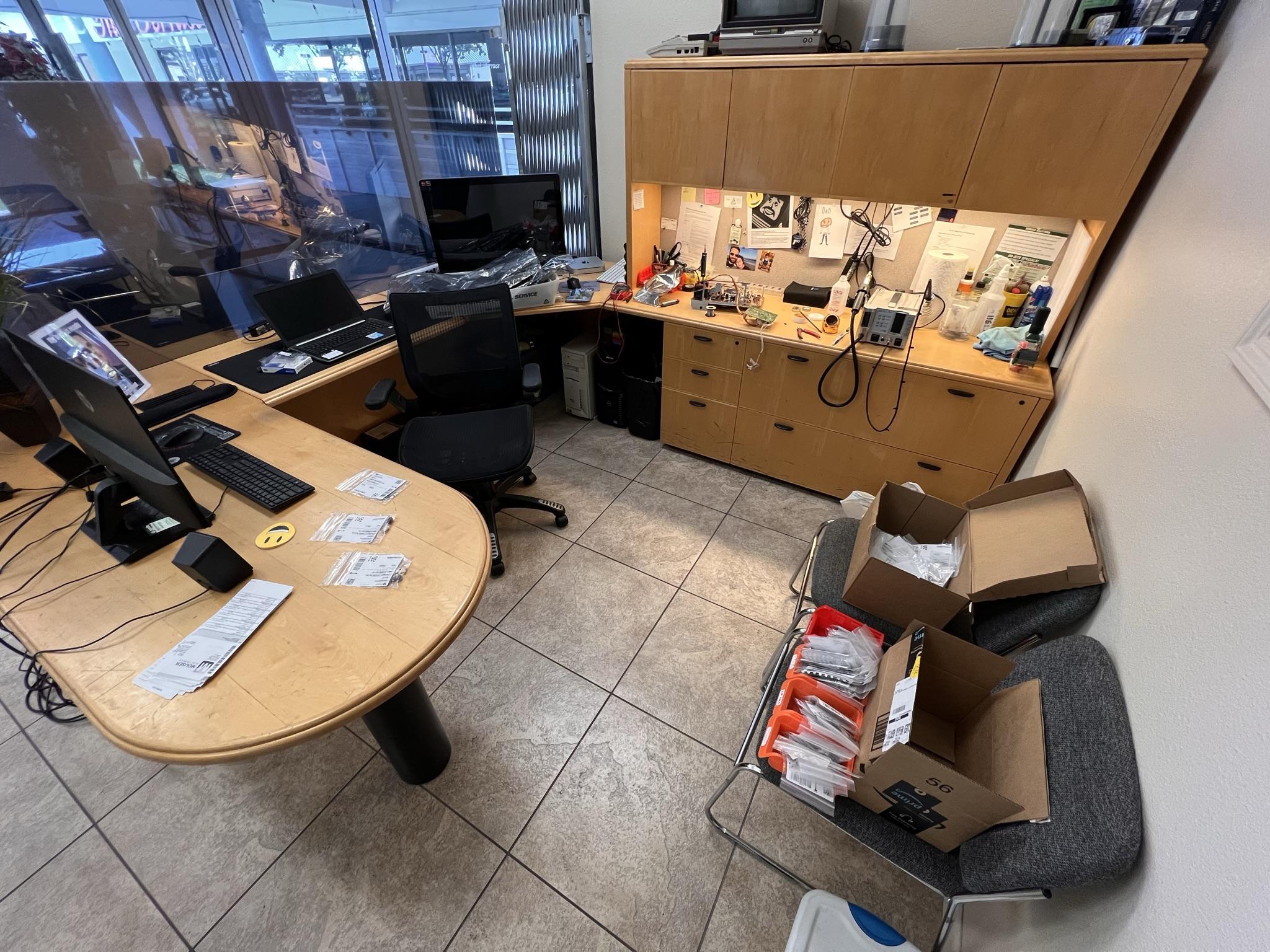
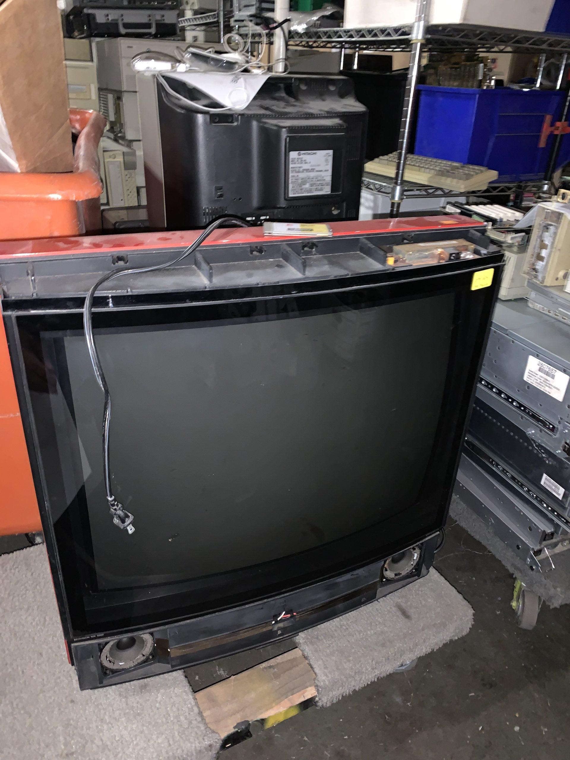
On a side note, when I dropped by black set off, in the garage was the red e-waste set, and a blue one my guy had just finished reparing, so it was a crazy site seeing all three sets together in one place. Will update again when I’ve got more info. 20 November 2023 at 17:27 #35493RallyMK1BRONZE Member
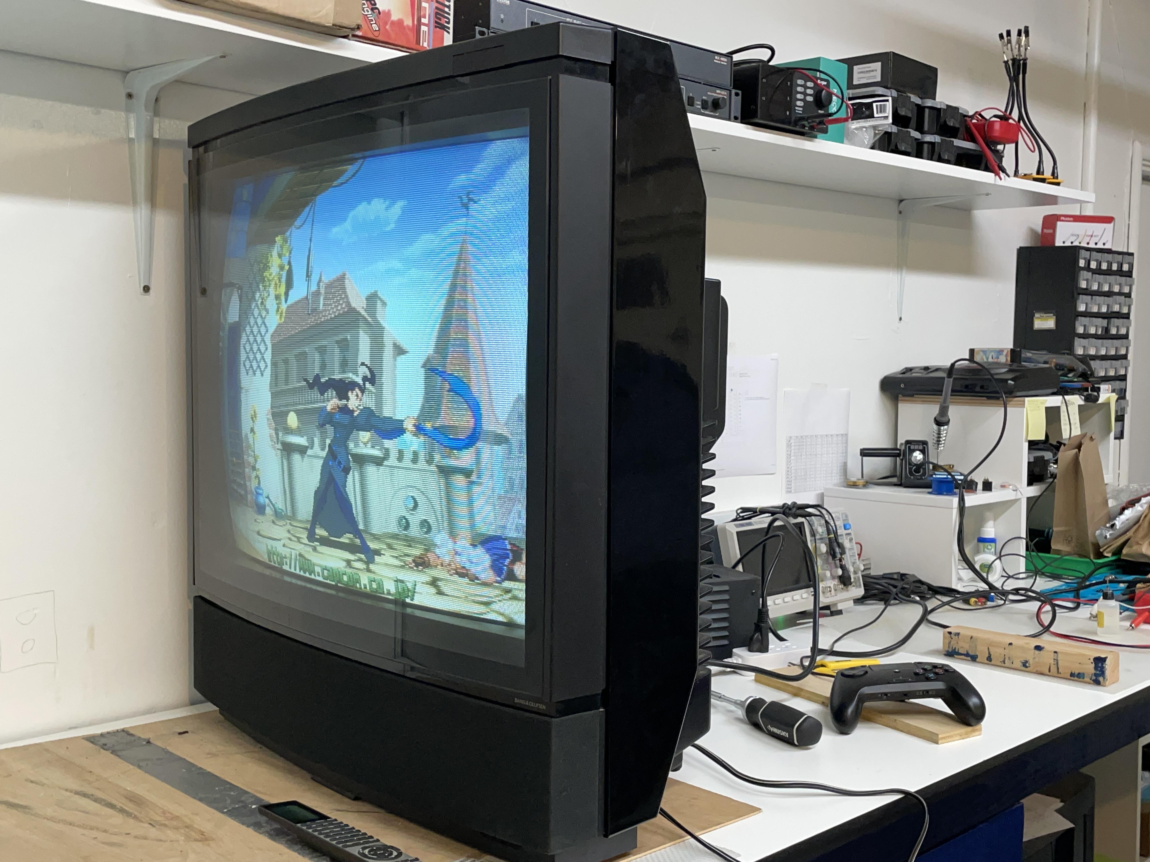
B&O first signs of life.
6 January 2024 at 20:48 #35494RallyMK1BRONZE MemberGuys, repairs are complete, and it’s in better shape than previously thought! It turns out the e-wasted B&O was an MX 5000, not a 5500, so its deflection circuit didn’t behave the right way with my yoke. The guy working on my set managed to get it up and running with my original boards, and found that the failure was mainly due to a mix of issues, including a blown HOT (which I had replaced!), trace corrosion from failed caps, a bad diode, and a shorted thermistor which ran the degauss coil.

All of those diags were far beyond my capabilities, so I never would have gotten this running without help, and a monumental amount of help at that.
This B&O comes home next week, and then, I get started on the VX 5000 repairs….6 January 2024 at 20:50 #35495RallyMK1BRONZE MemberHere’s a nice closeup:
14 January 2024 at 23:00 #35496jdzwonnikBRONZE MemberGreat article. Are you able to tell me how you changed the geometry on your tv? I got an MX5000 yesterday and the geometry is all over the place. I saw someone say that these tvs don’t have the service pins to short out?
Thanks in advance
21 January 2024 at 00:10 #35497RallyMK1BRONZE MemberThere are pots internally, no digital adjustment on this one. I haven’t gotten into the service menu so far, just haven’t needed to. I’ll explore that later if it comes down to it.
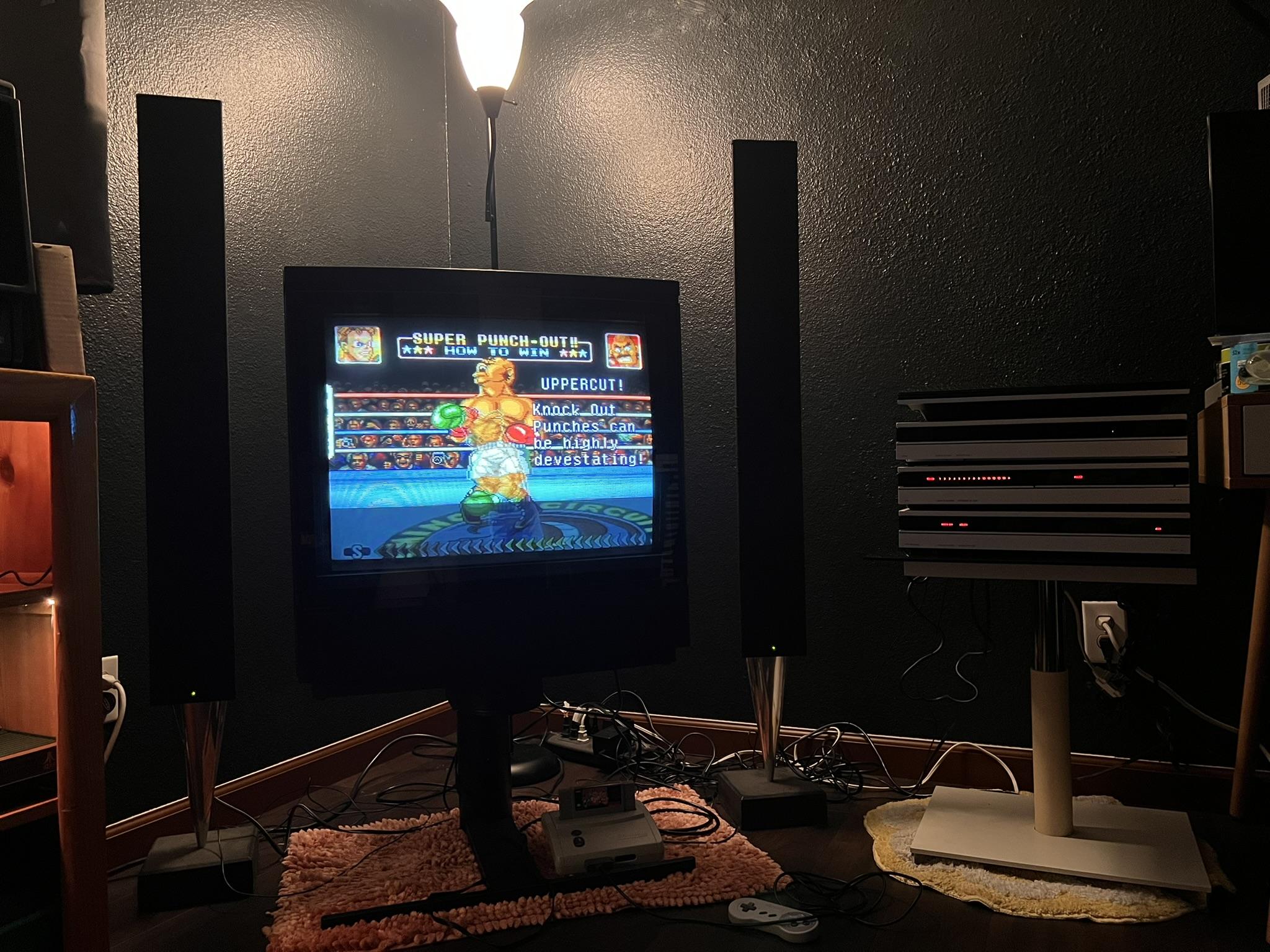
Here’s a pic of it in its final spot, matched up with the Beosystem 6500 and some Beolab speakers.
-
AuthorPosts


- You must be logged in to reply to this topic.