Home › Forums › Product Discussion & Questions › BeoGram › missing BG4000
- This topic has 31 replies, 3 voices, and was last updated 3 years, 8 months ago by
Bernie.
-
AuthorPosts
-
12 March 2022 at 01:09 #33028
hcraig244
SILVER MemberWell…..here we go, first post is another episode in the continuing saga of the missing Beogram and its errant power supply….the doner machine turned up
12 March 2022 at 13:12 #33029hcraig244
SILVER MemberThe replacement toroidal is a good fit dimensionally…..will fit above the fusebox nicely…
12 March 2022 at 13:35 #33030hcraig244
SILVER Member230vac power cable and improvised fusebox connected up…..
12 March 2022 at 13:43 #33031hcraig244
SILVER MemberThis is the data sheet for the transformer….yellow and black connected together to provide the 24v supply across orange and red to the 24vdc rectifier, connecting red and black (12v) to the 6vdc rectifier…..sounds straightforward enough
12 March 2022 at 13:45 #33032hcraig244
SILVER Memberjust getting my head around the order of things here….I will try harder
12 March 2022 at 13:49 #33033hcraig244
SILVER MemberThis is the data sheet for the voltage regulator…
12 March 2022 at 13:58 #33034Very nice and tidy Craig.
12 March 2022 at 14:00 #33035hcraig244
SILVER Membertimestamp is a bit of a challenge here……my replies are all jumbled up, however wired up the transformer and powered up….slowly with the variac and watched the output of the 6vdc regulator it came up nicely…..and as i wound up the variac the output started to fall back to 0vdc….like a capacitor charging up?
12 March 2022 at 14:30 #33036hcraig244
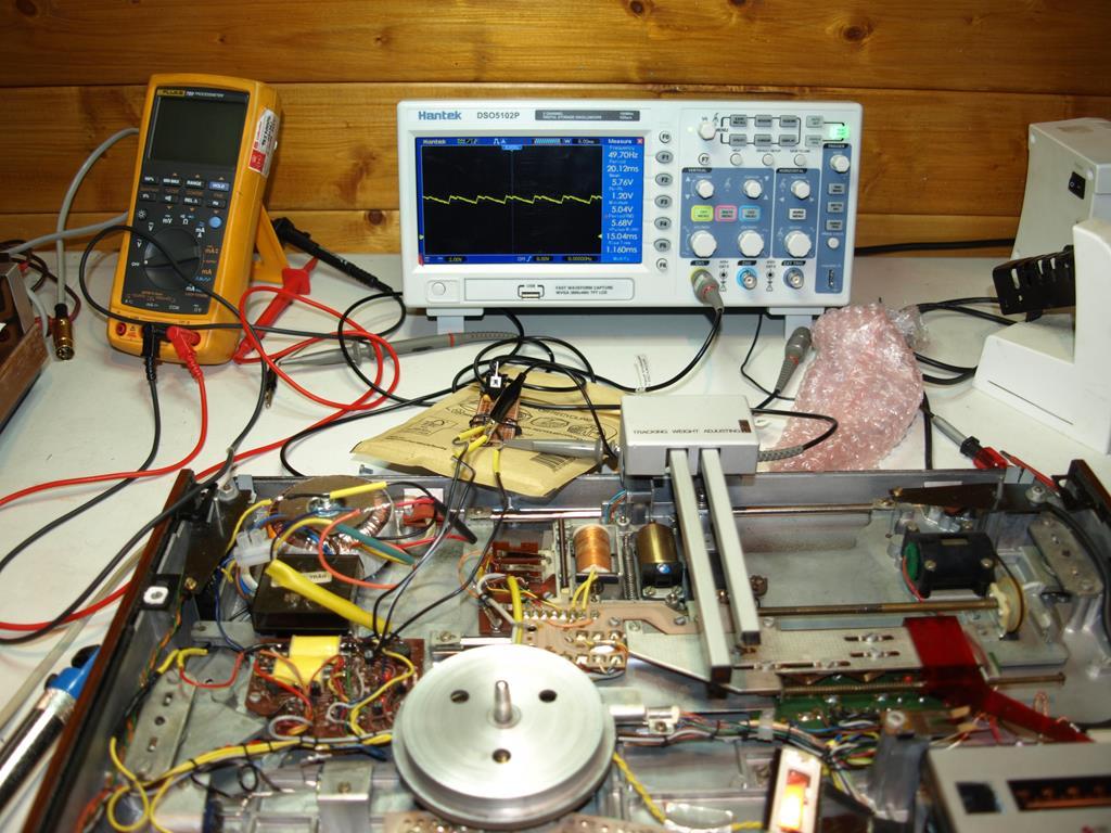
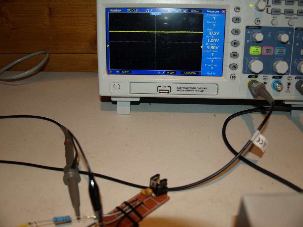
SILVER MemberThis is how it looks, I have the regulator connected on leads to allow measurments to be taken easily
12 March 2022 at 14:32 #33037hcraig244
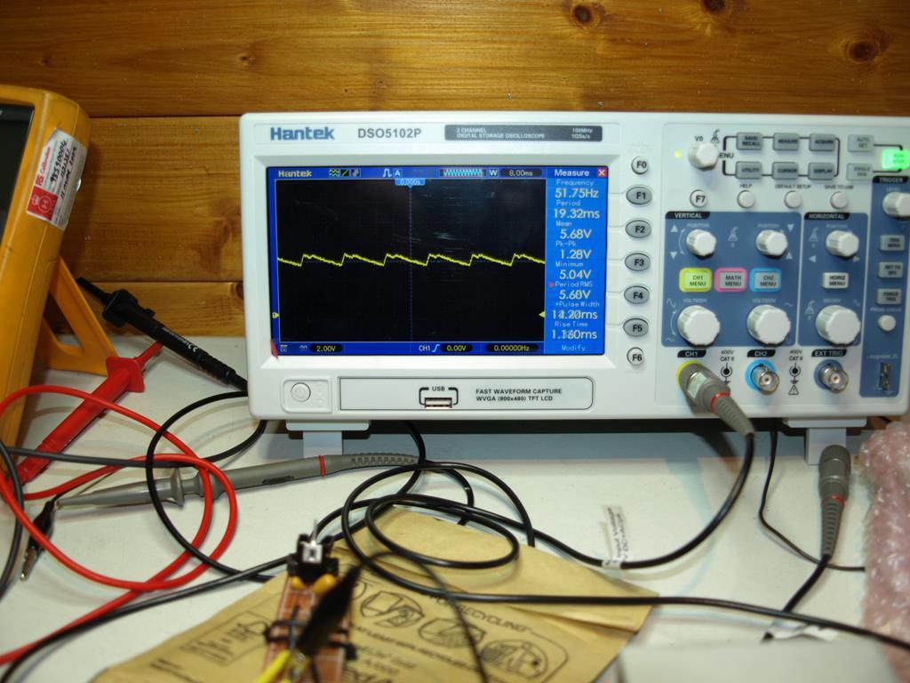
SILVER MemberThis is the regulator 6vdc output under operating load
12 March 2022 at 14:42 #33038hcraig244
SILVER MemberHowever the 6vdc fell off when the regulator went into high temp cut off……it was getting very hot!….few measurements revealed that I am getting 24v at the input to the voltage regulator instead of the 12v i was expecting, the output from the transformer is 12v to the 6v rectifier…..
12 March 2022 at 15:12 #33039hcraig244
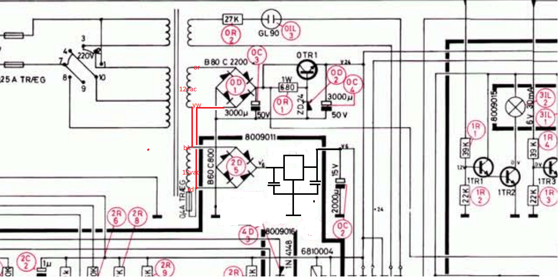
SILVER MemberThis is how the new power supply is tied in…
13 March 2022 at 13:09 #33040hcraig244
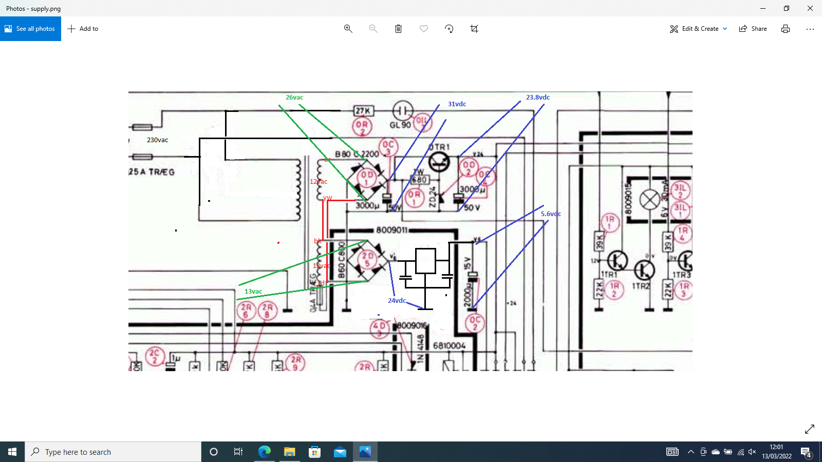
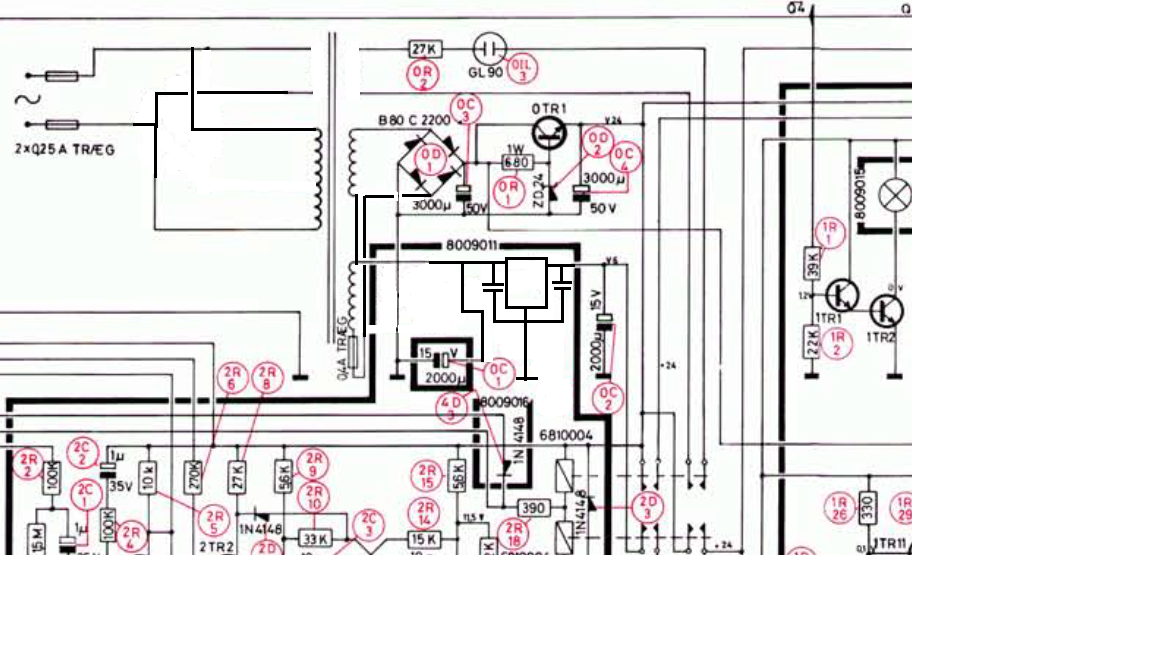
SILVER MemberOk…..cleaned the drawing up to include the actual transformer wiring details and took some measurements…..these are all with the turntable running and under normal load conditions…everything works fine though the voltage regulator gets hot…put a heat sink on it which helps quite a bit.
13 March 2022 at 13:27 #33041hcraig244
SILVER MemberThis looks like an issue with the centre tapped transformer, I have read on the internet that a common neutral on the DC outputs of dual supplies of different voltages fed from centre tapped transformers are not allowed, this may be my problem.
When I disconnect the 24vac supply from the transformer to the 24vdc rectifier I get the expected 12vdc from the output of the 12vdc rectifier, so I know the 12vdc rectifier is working fine..I have no problems with the 24vdc side which is working fine, as this is the required higher supply im not surprised. I cant see anything untoward except the common neutral to both rectifiers……..any advice regarding this would be welcome, as always ;¬)
21 March 2022 at 19:08 #33042hcraig244
SILVER Membermoving on…..got the dual outputs from the centre tapped transformer sorted out, after a good deal of head scratching….and glasses of wine! I removed the 6vdc bridge rectifier and reinstalled the smoothing capacitor, output from the centre tap connection of the transformer to the input of the new regulator and now get a decent full wave rectification.
cant seem to get a jpeg loaded……..maybe later
21 March 2022 at 19:15 #33043hcraig244
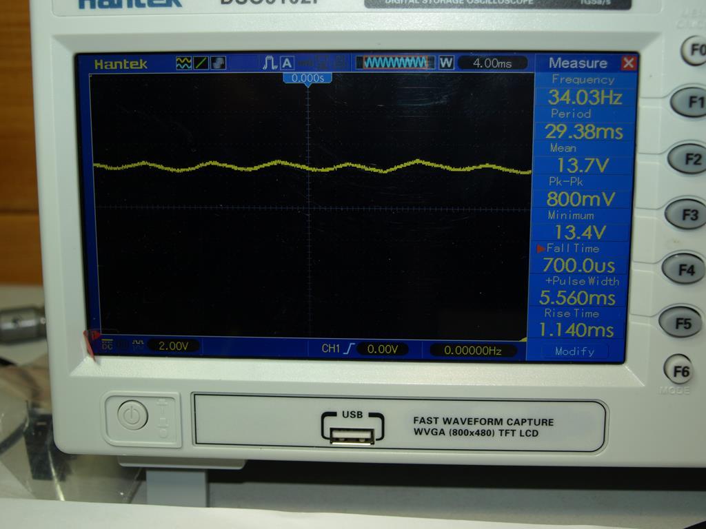
SILVER Memberthis is the input to the new voltage regulator from the centre tap of the the transformer, much improved though still a little high, this measurement was taken under load, this was previously sitting at 24v
23 March 2022 at 09:27 #33044hcraig244
SILVER MemberThis is the current wiring detail I have implemented……..
23 March 2022 at 09:28 #33045hcraig244
SILVER MemberTried a 22 ohm resistor in line with the regulator and this dropped the input voltage to a little over 10vdc…the heat dissipated by the regulator has dropped and the resistor is doing some of the work….
23 March 2022 at 11:33 #33046hcraig244
SILVER MemberAs I’m now down to 1 bridge rectifier I thought it would be wise to check a few things out before I do a lengthy test run:
Output from the new 6vdc regulator = 160ma under operating load
Output from the existing 24vdc regulator (0tr1) = 440ma under operating load
The transformer arms are good for 1.25A so I think we’re good to go, the bridge rectifier is rated at 3.7A. I will monitor the temperatures of all components, TR1 particularly though the data sheet says its good for 80w (seems high to me).
Also I have ordered a 33 ohm 3w resistor to see if I can drop all the heat over it instead of the regulator, I can then fasten the resistor to the chassis for cooling……
26 March 2022 at 10:55 #33047hcraig244
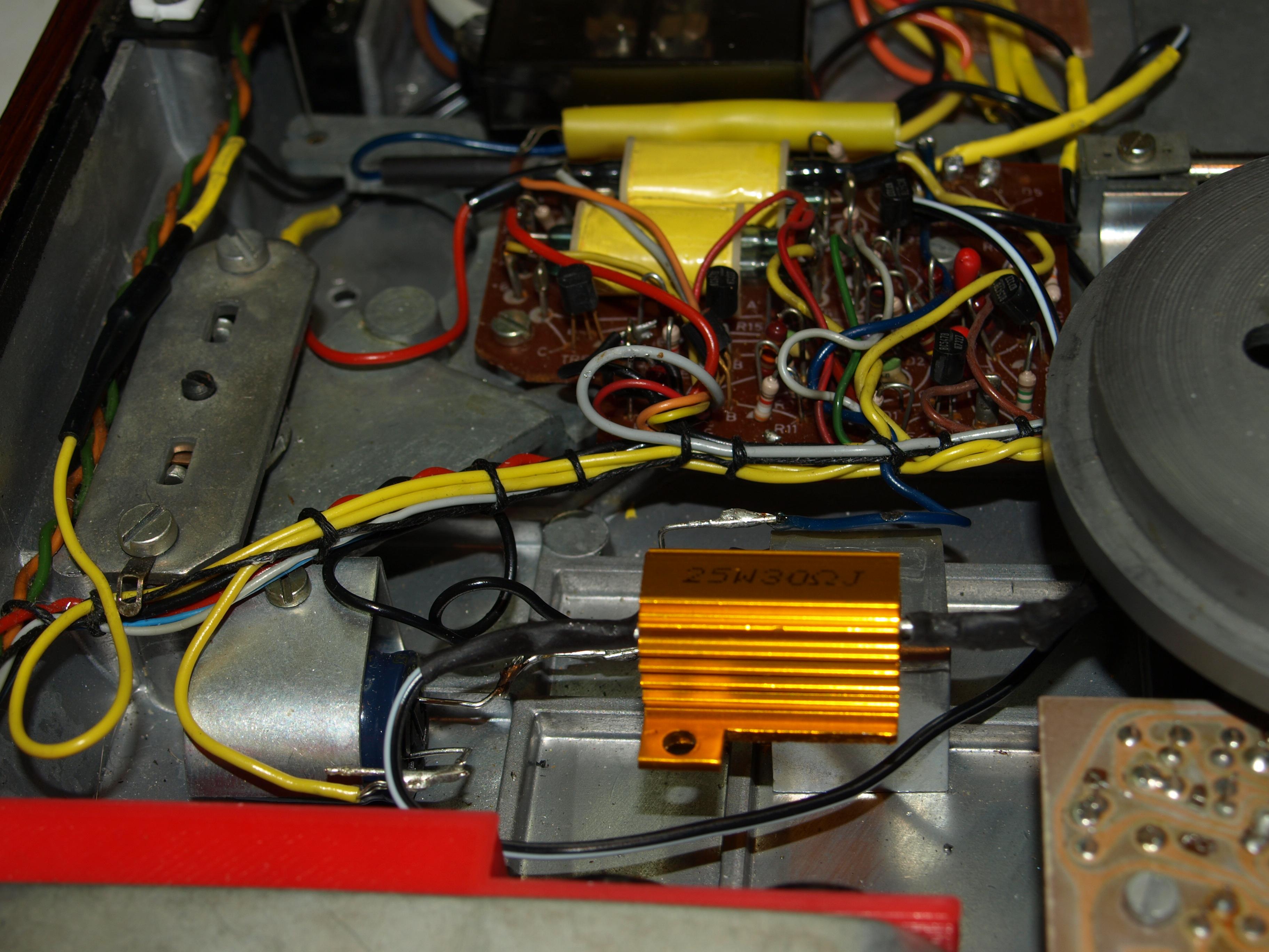
SILVER MemberResistor received, however I ordered a 3w component and received a 25w instead……bit overkill but quite adequate….
-
AuthorPosts
- You must be logged in to reply to this topic.


