Home › Forums › Product Discussion & Questions › BeoLink › MCL2 AV no 5,5V
- This topic has 17 replies, 2 voices, and was last updated 2 years, 11 months ago by
Madskp.
-
AuthorPosts
-
4 February 2023 at 12:53 #43528
Madskp
GOLD MemberI have aquired a MCL2 AV for some testing purposes.
first test of it with 15V power, tranciver, speakers in powerlink socket, and beocord 3500 in tape socket. No reaction to remote. No led light in the tranciver.
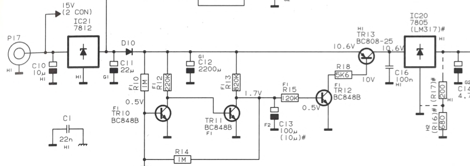
tried to do some measurements, and there is no 5,5V after IC20
I got 11.6V before IC20 where the servicemanual says 10.6V
i got 12V after IC21 and 6V after IC12 asit should be
any clues what to look for?
Location: Denmark
5 February 2023 at 11:06 #43529Madskp
GOLD MemberAm I right in assuming that the MCL2 AV will start up and work stand alone without connection to a MCL master?
Location: Denmark
5 February 2023 at 11:22 #43530 Moderator
Am I right in assuming that the MCL2 AV will start up and work stand alone without connection to a MCL master?
Yes – I used to use one like that as a stand alone amp for my PC. It even gave two-way IR in stand-alone mode!
Are you using the offical Power Supply, or the supply feed from an MCL2P? Mine worked with both.
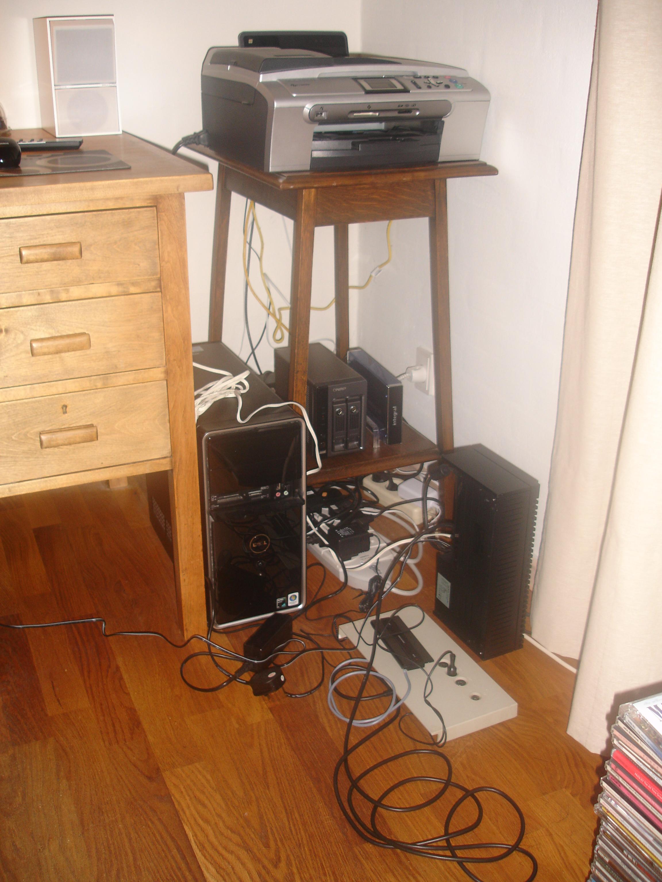
EDIT: I know you’d like to see my neat cabling …. ?
Location: Warwickshire, UK
My B&O Icons:
5 February 2023 at 11:47 #43531Madskp
GOLD MemberYes thats the way cabling should look like in a man cave ?
I dont have the original PSU so I am using a bench power supply with wires soldered to the PCB. It should be ok as I am getting the right voltage levels other places on the board except that 5.5V that is not showing up.
Location: Denmark
5 February 2023 at 12:02 #43532 Moderator
Have you checked the connection/wiring of the IR eye? I think that is one of the ‘users’ of the 5.5V supply, hence could be shorting it out if wired incorrectly?
Location: Warwickshire, UK
My B&O Icons:
5 February 2023 at 12:17 #43533Madskp
GOLD MemberHi again and thanks for the hint.
the problem persists without the IR eye connected, so may not be that. Right now im suspecting an SMD transistorLocation: Denmark
5 February 2023 at 15:07 #43534Madskp
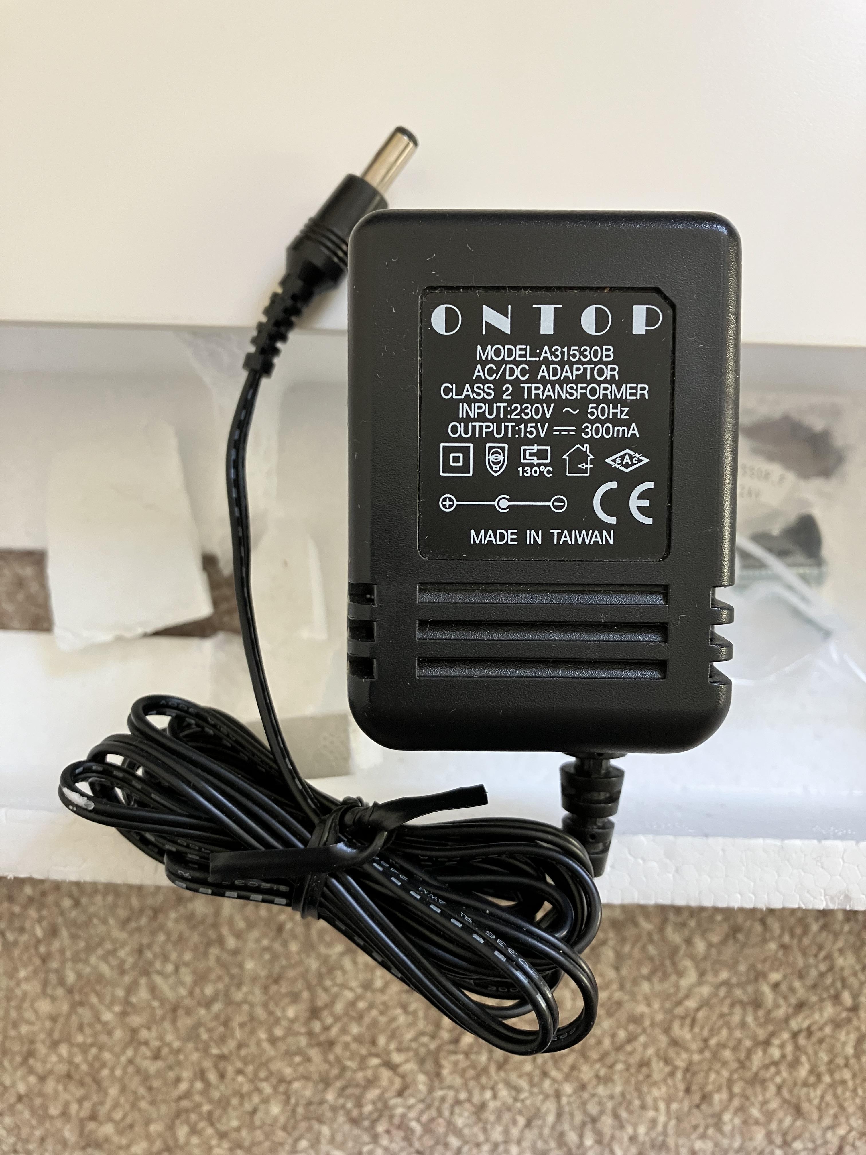
GOLD MemberGuy, is there a pin connection drawing on the PSU for your MCL2-AV if you have it handy?
thsnks in advance
Location: Denmark
5 February 2023 at 15:36 #43535 Moderator
Here you go: (I am getting better at finding things!)
Location: Warwickshire, UK
My B&O Icons:
5 February 2023 at 15:56 #43536Madskp
GOLD MemberThank you very much. Then I can rule out errors regarding these specifications
Location: Denmark
5 February 2023 at 16:00 #43537 Moderator
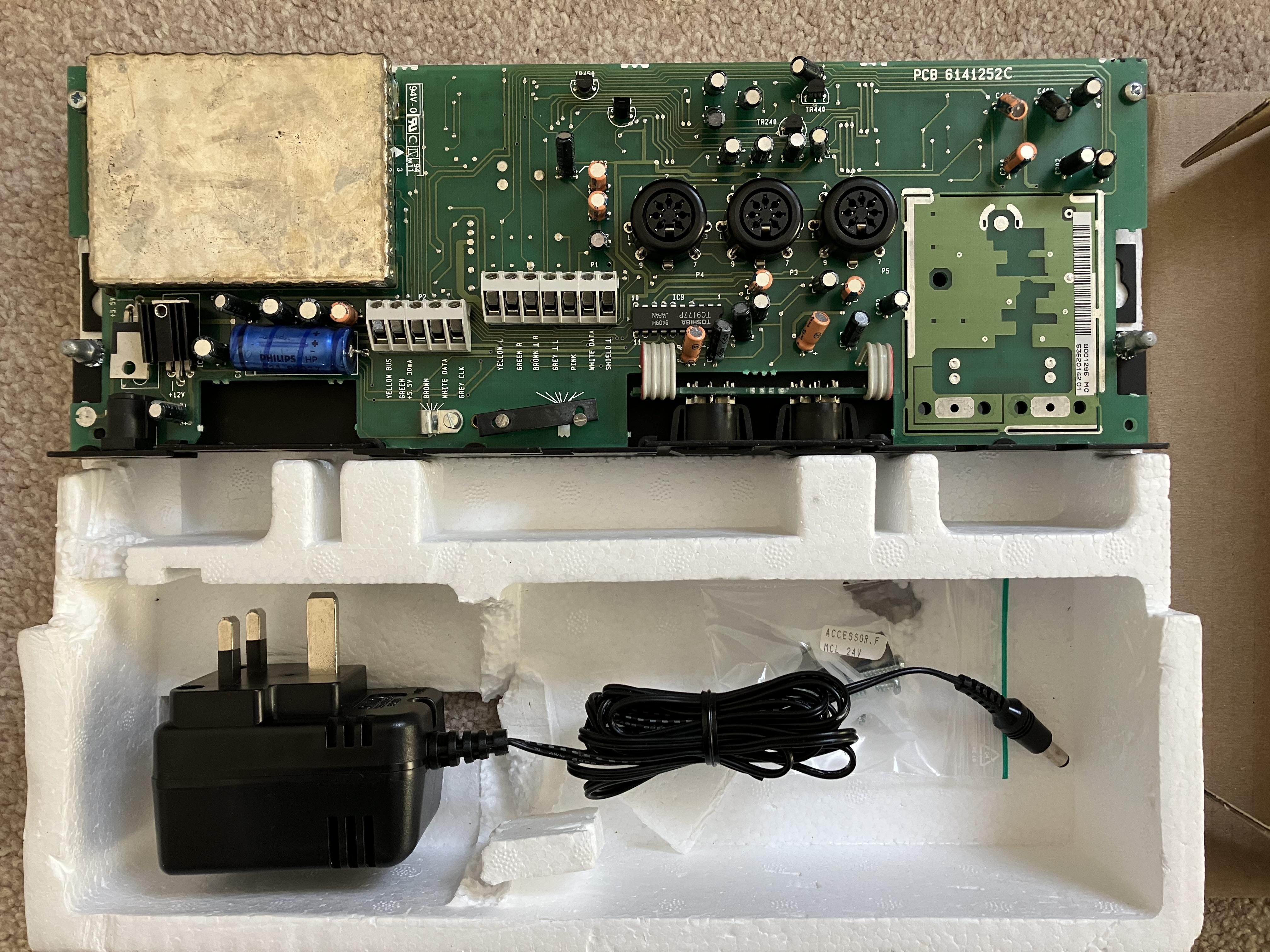
Not sure if this helps – I think this is quite a late model without the passive speaker or RF connections. The label says Type 2032.
Location: Warwickshire, UK
My B&O Icons:
5 February 2023 at 17:02 #43538Madskp
GOLD MemberThanks again. Mine is type 2020 and has a lot more going on
guess the same applies to the bottom og the PCB.
but great to have some sort of reference.
I had some corrospondance with the seller and he tells me it didnt work with a power supply for him, but it did connected tol the MCL2P.
cant really see what difference that should make?
Location: Denmark
5 February 2023 at 17:31 #43539 Moderator
The one that I used as a stand-alone was also Type 2020 – you can see the TV co-ax socket in my first photo.
I suppose that the 2020 is older therefore has more chance of a fault. Perhaps someone has connected an incorrect PSU in the past, or reversed the polarity and damaged IC20 (or one of the many extra components in the earlier model).
I just checked my PSU with no load and it measured 23V.
Location: Warwickshire, UK
My B&O Icons:
5 February 2023 at 17:43 #43540 Moderator
With the PSU connected to my Type 2032:
Input leg of IC21 is reading 20.4V
I get the correct 12V and 5V readings at IC21 and IC20 outputs respectively.
Maybe carefully increase your supply voltage?
Location: Warwickshire, UK
My B&O Icons:
5 February 2023 at 17:48 #43541Madskp
GOLD MemberOk thats interesting. I will try that when I have the time to sit with it again
Location: Denmark
9 February 2023 at 19:46 #43542Madskp
GOLD MemberOk, tried a little back and forth with the MCL2AV, but have only got small timeslots to work with it.
Carefully applying higher voltage did not change anything. Guess under normal circumstances it will work within a certain voltage range as all input voltage either goes through the voltage regulator IC21 or to activating a relay switch.
I then have controlled most of the Caps in the power circuit, soldered the out and tested the with a component tester and all seems to be within range still after all these years.
As mentioned earlier I suspected a transistor, and ended up testing TR10, TR11, TR12, TR13. TR13 is the only one of the who fails the test. It only shows up as a diode on the tester.
To further test the unit I tried to apply 10.6V after this transistor before IC20 as shown on the diagram in the servicemanual, and the the unit was alive. Could control a Beocord 3500 with remote and get sound out on powerlink.
So hopefully replacing TR13 will make it work fully again. Ordered a bunch of the on Ebay, and gotta get practicing on my SMD soldering skills with hot air.
Will update when I have the new part.
Location: Denmark
21 February 2023 at 19:05 #43543Madskp
GOLD MemberSo got the transistor. I ended up buying BC807-25 instead of BC808-25 (they have alomost identical data) as it was easier to come by.
desoldered the old TR13 with hot air, and soldered in the new one.
Testing and red light turns on in the IR eye. Meassuring with multimeter shows 5.46V so very close to the specified 5.5V.
So now I just need one Bench supply for it until I find a 15V power brick.
unfortnuatly the ribbon cable to the PL connectors broke of in the proces so need some extra repair work before its ready for further testing
Location: Denmark
22 February 2023 at 14:41 #43544 Moderator
until I find a 15V power brick
Great work fixing the fault!
If you intend to use it with passive speakers you could perhaps look for an MCL2P with its built in 15v power supply?
Location: Warwickshire, UK
My B&O Icons:
22 February 2023 at 18:36 #43545Madskp
GOLD Memberuntil I find a 15V power brick
Great work fixing the fault! If you intend to use it with passive speakers you could perhaps look for an MCL2P with its built in 15v power supply?
Thats right. Don’t know what the final use will be for it for now, but it sure has some possibilites
Location: Denmark
-
AuthorPosts
- You must be logged in to reply to this topic.




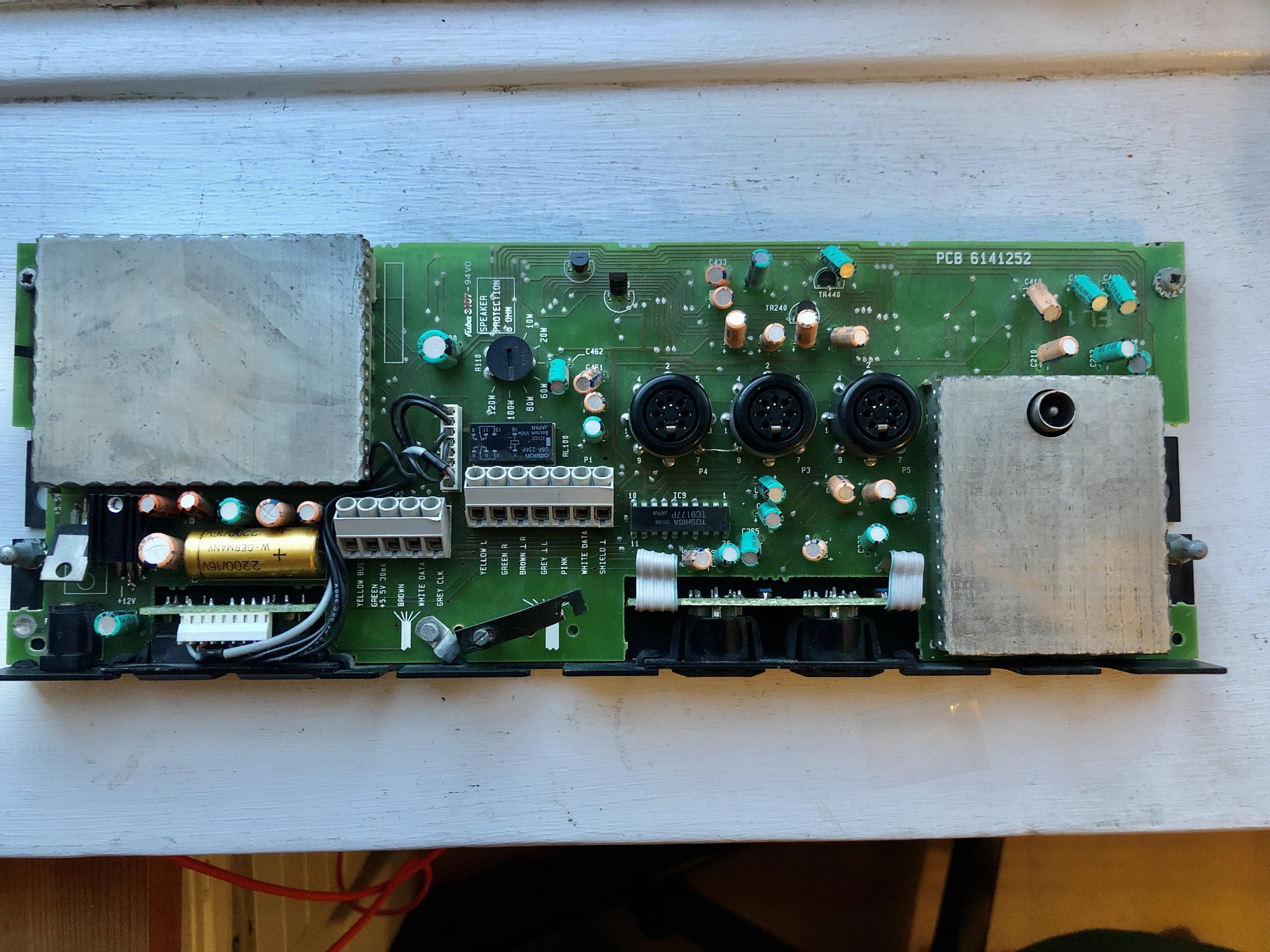 guess the same applies to the bottom og the PCB.