


Home › Forums › Product Discussion & Questions › BeoGram › DIN > Phono adapter cable for Beogram
Tagged: adapter cable, adapter for beogram, din cable
- This topic has 6 replies, 4 voices, and was last updated 1 year, 5 months ago by
 Philip Pedersen.
-
AuthorPosts
-
19 October 2024 at 20:14 #60277
 Philip PedersenBRONZE Member
Hi all 🙂
New member here! I tried to use the search function, but could not find any valid existing threads, so I decided to create a new one.
I want to make and solder my own DIN-adapter cable for my Beogram, but I can not find any “schemetics” for this type of cable anywhere online.
Do any of you kind folks have it and would you be able to share? I have tried and tested a couple of options. This one worked the best:
Red to the left-most terminal.
White to the right-most terminal with a jumper to the 1st from the left terminal.
Ground wire (yellow) to the middle terminal.
All shield wire soldered together and then soldered to the metal part of the DIN-connector.
This works somewhat, but it is still playing with some ground buzz and it is way to fragile, so something must be wrong.
Please advice. Picture of a generic cable added for reference.
Attachments:
You must be logged in to view attached files.20 October 2024 at 10:42 #60291mcevedy@mac.comGOLD MemberThere is an earth that goes to the round metal part of the DIN plug. A wire from this to an earth will get the hum to go away.
My B&O Icons:
 20 October 2024 at 11:11 #60293
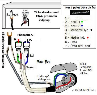
Here’s one of Peter Pan’s diagrams that should be useful: (from https://www.hifi4all.dk/forum/forum_posts.asp?TID=32157&PN=1)
(However he seems to have ‘mirror imaged’ the solder side of the DIN socket: Red connection should be to what he has labelled as 4, and white to 1)

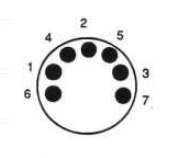
EDIT: For clarity, here is the correct pin numbering when viewing the solder side of a 7-pin DIN plug, or viewing into the ‘open’ side of a corresponding socket:

Location: Warwickshire, UK
My B&O Icons:
20 October 2024 at 13:04 #60309MadskpGOLD Member@Guy: Pin 3 and 5 for left and right signal should be correct
Edit: But I see the point that in a female DIN connector the pins are reversed.
Location: Denmark
20 October 2024 at 19:51 #60320Philip PedersenBRONZE MemberHi all. Thank you very much for the kind feedback! An archeive such as Peter Pans diagrams was exactly what I was hoping for.
I only have 5-pin female DINs available which should be sufficient?
Any major differences in the diagram from the 7-pin? Does do numbering scheme change?
20 October 2024 at 23:14 #60322Any major differences in the diagram from the 7-pin?
No. Just delete/ignore pins 6 and 7.
Location: Warwickshire, UK
My B&O Icons:
24 October 2024 at 20:08 #60429Philip PedersenBRONZE MemberThank you once again for your feedback. I ended up simply mirroring the gramophone cable. So left to right is white to first pin, red to second pin and then the combined shield wire of white and red goes to the third pin. As Peter mentioned, it is also crucial to solder the inside and outside wires of the yellow cable (shield) to the metal part of the cable itself – just writing this for anybody stumbling upon this thread in the future 🙂 Thanks again!
-
AuthorPosts


- You must be logged in to reply to this topic.