


Home › Forums › General Discussion & Questions › General Discussion & Questions › B&O Loudspeaker Switch IR Eye pinout help requested
- This topic has 11 replies, 5 voices, and was last updated 1 year ago by
 kirin.
-
AuthorPosts
-
14 May 2022 at 09:01 #34821
 BlokkenpilootBRONZE Member
Hi all,
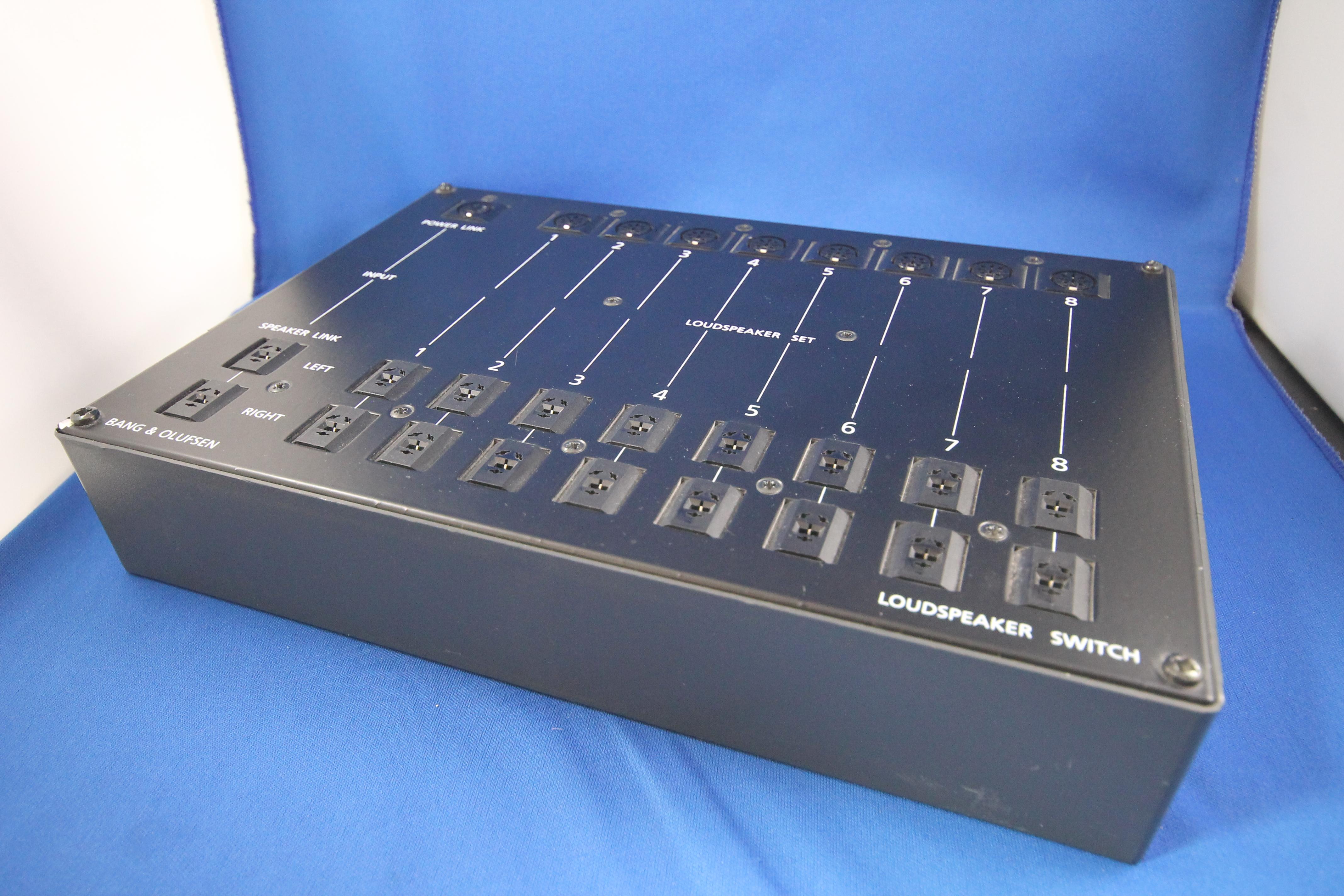
I’m trying to test my “Loudspeaker Switch” When i turn it on, it automatically goes to channel 1, but in order to change channels, you need to connect an IR receiver.
Now according to the archieved forum “The IR looks identical to the MCL IR but it’s not the same. It has an 6 pin DIN lead, but only pins 1,3+5 are used, number 8712009″
From: https://archivedforum.beoworld.org/forums/t/35139.aspxNow i do have an MCL IR and an DIN cable that fits, but i can only find IR pinouts for DIN connectors with more pins.
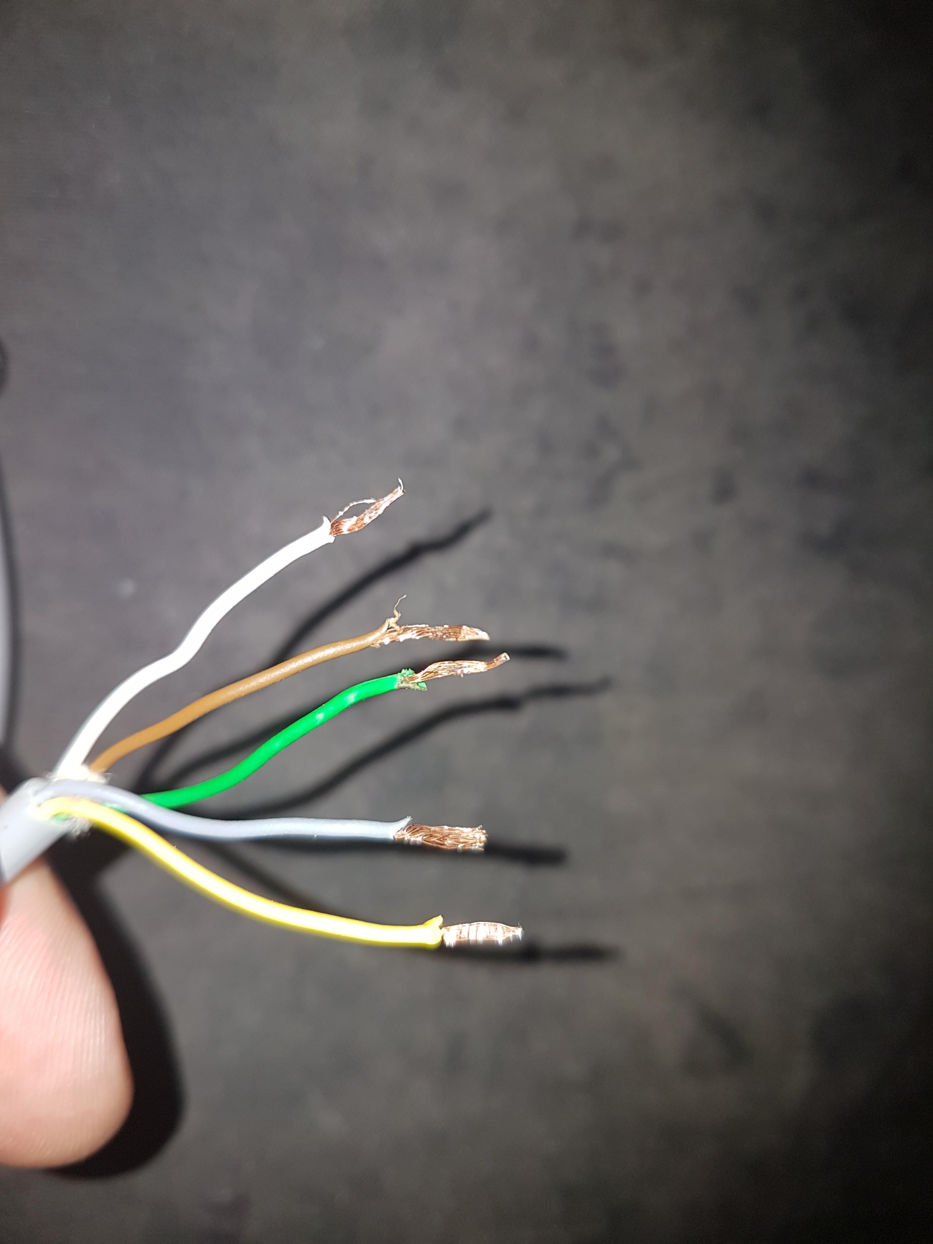
Can someone tell me to which pins i should connect the wires from the MCL IR? i suppose it’ll be the Green: 5v, Brown: ground? and White: Data. But correct me if i’m wrong!


15 May 2022 at 10:03 #34822Can someone tell me to which pins i should connect the wires from the MCL IR? i suppose it’ll be the Green: 5v, Brown: ground? and White: Data. But correct me if i’m wrong!
I made some notes when I used an MCL sensor as a Beoport IR sensor. The three connections that you require are:
Ground – Brown
IR Data – Yellow
+5v – GreenWhite is indeed a data connection but is used for relaying the other functions within the MCL sensor, particularly from pressing the buttons (eg Mute and Timer).
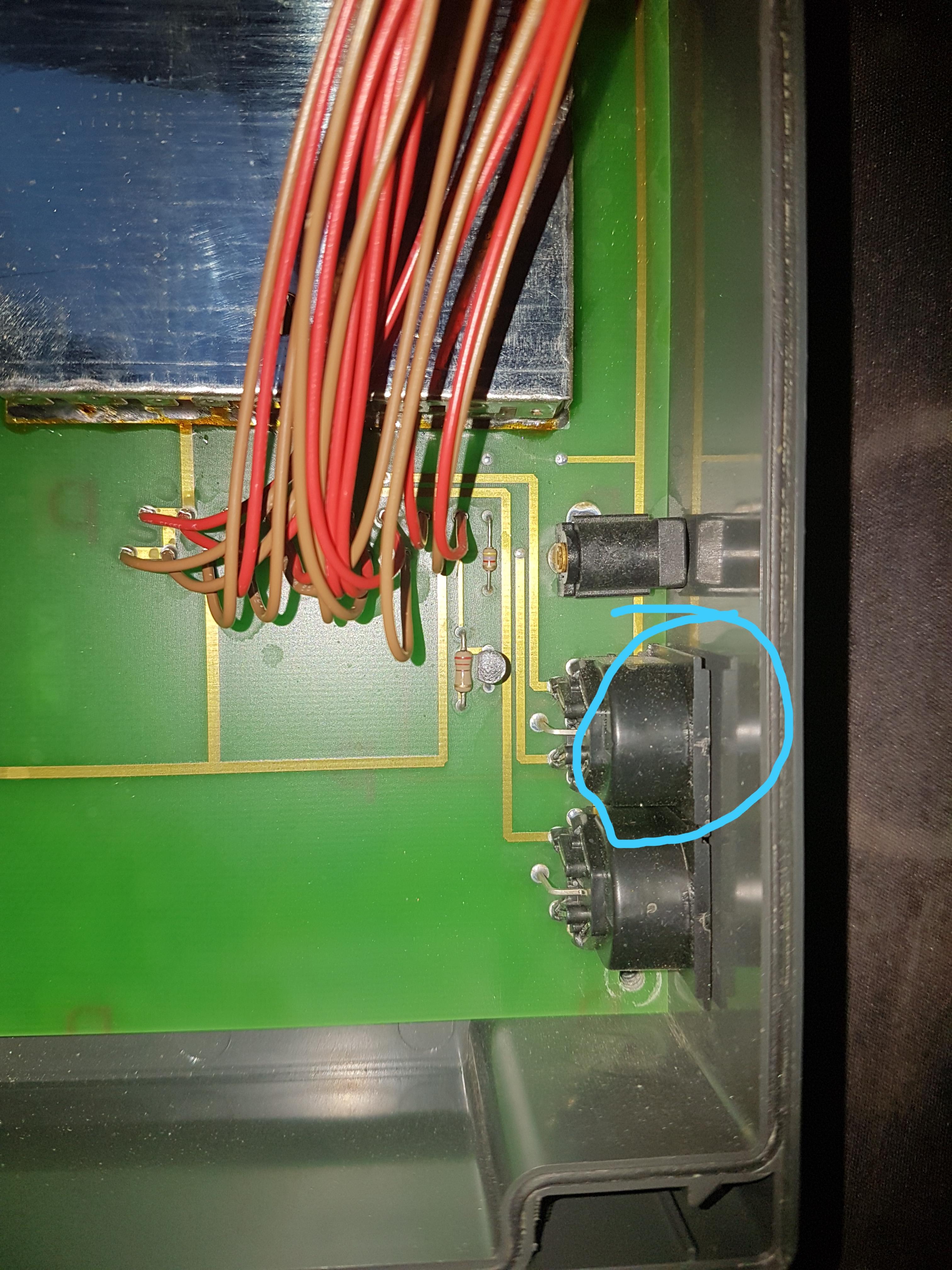
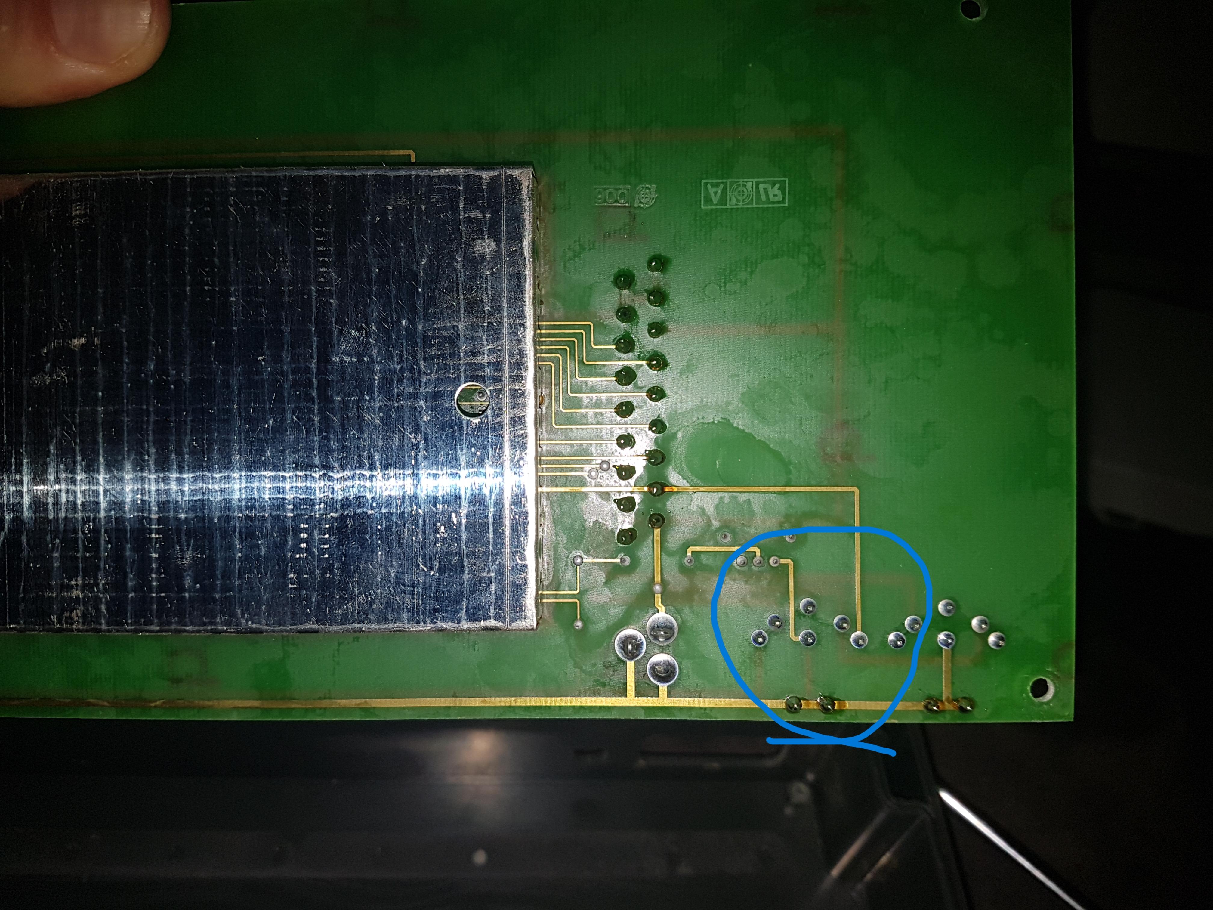
Hopefully you can work out the correct 5 pin DIN pins from having a look at the internal wiring of the loudspeaker switch.
IMPORTANT EDIT: I have just realised that I actually used a VX sensor (similar to MCL but without Mute and Timer buttons) when I was experimenting. The VX sensor only has three wires, hence IR data had to be Yellow by process of elimination! I think that in your MCL sensor then ‘White’ may well be the data connection that you need. Sorry for the confusion!
Location: Warwickshire, UK
My B&O Icons:
 15 May 2022 at 10:57 #34823
I made some notes when I used an MCL sensor as a Beolink PC IR sensor. The three connections that you require are: Ground – Brown IR Data – Yellow +5v –
Hi Guy, does that mean you can use MCL IR sensors (square ones) with more modern hardware that need round sensors ?
To be more precise, would an MCL82 type 2041 sensor be able to control a beolink passive ?
Thank you.
Location: Paris France
15 May 2022 at 11:47 #34824does that mean you can use MCL IR sensors (square ones) with more modern hardware that need round sensors ?
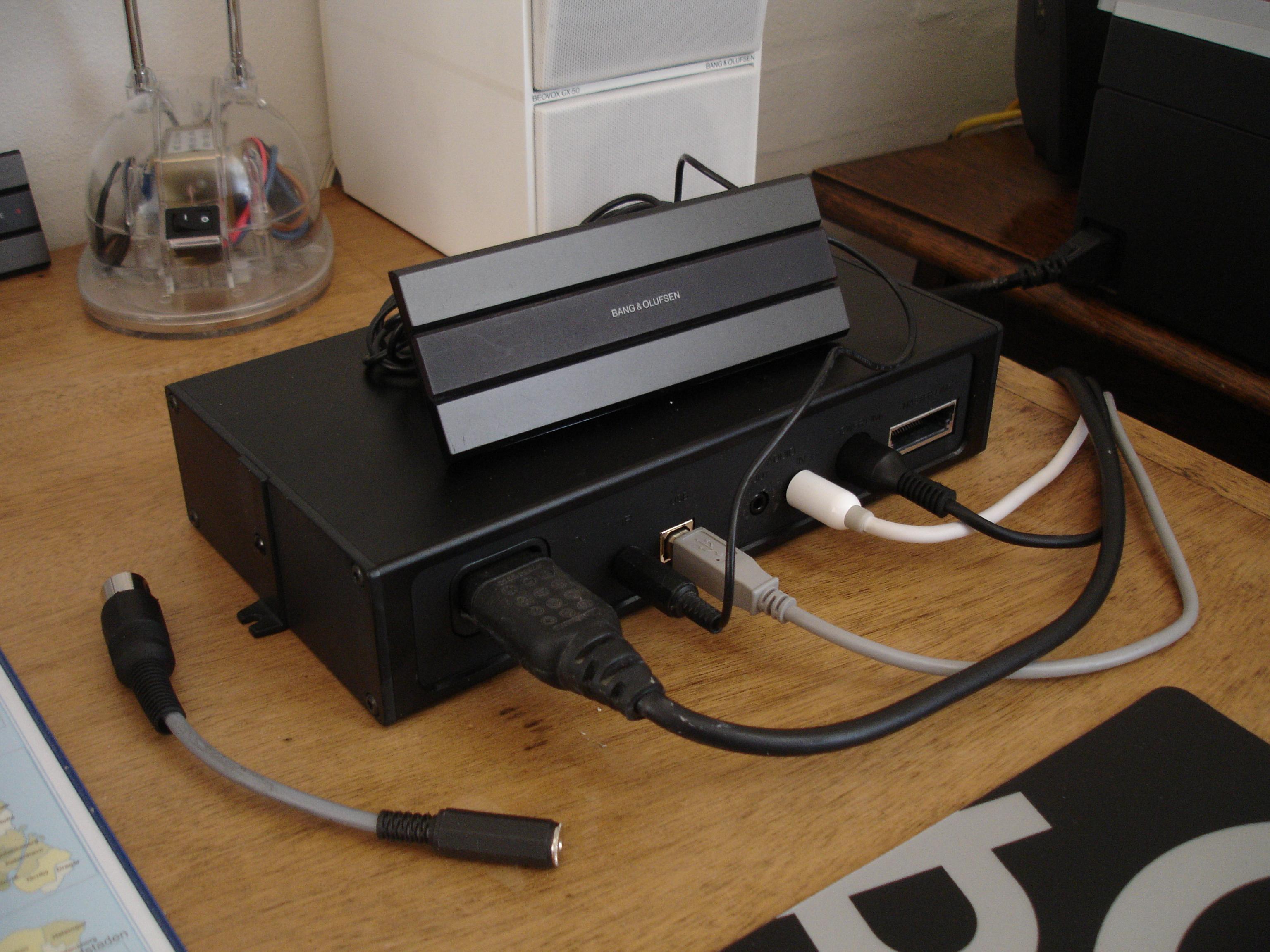
I definitely used an old VX sensor as the IR input for a Beoport, and I remember making a short adaptor so that I could also connect it to a Beolink Passive or Active – see photo (adaptor lying on desk to the left):

But I have never owned any of the older MCL82 equipment hence can’t comment. However, if you can determine the correct +ve, ground and ‘IR data’ connections in the MCL82 sensor (and if it also runs on a 5V supply) then it would be worth a try to see it it works as an IR sensor for newer equipment.
I may have posted more about IR sensors in the archived forum – hopefully it will be back soon!
Location: Warwickshire, UK
My B&O Icons:
16 May 2022 at 08:40 #34825Thank you Guy, after a little search the Beolink MCL82 type 2041 works with the BS5000 and BC7700. The search also returned a little extract from the Beoworld product page that says: “It was superseded by the later MCL2 system which used Beolink 1000 codes.”
So I’ll assume it may potentially not work with moderne remotes. When I had a full 5000 system, I used little cheap IR repeater to help the return of the IR signal to the remote. It did work when the same repeater don’t with modern Beo remotes (1000/4/6/5000). So the theory is it wont work.
To the OP, apologies for this little out of topic, I felt like it didn’t deserved a full thread on it’s own. It’s now ended.
Location: Paris France
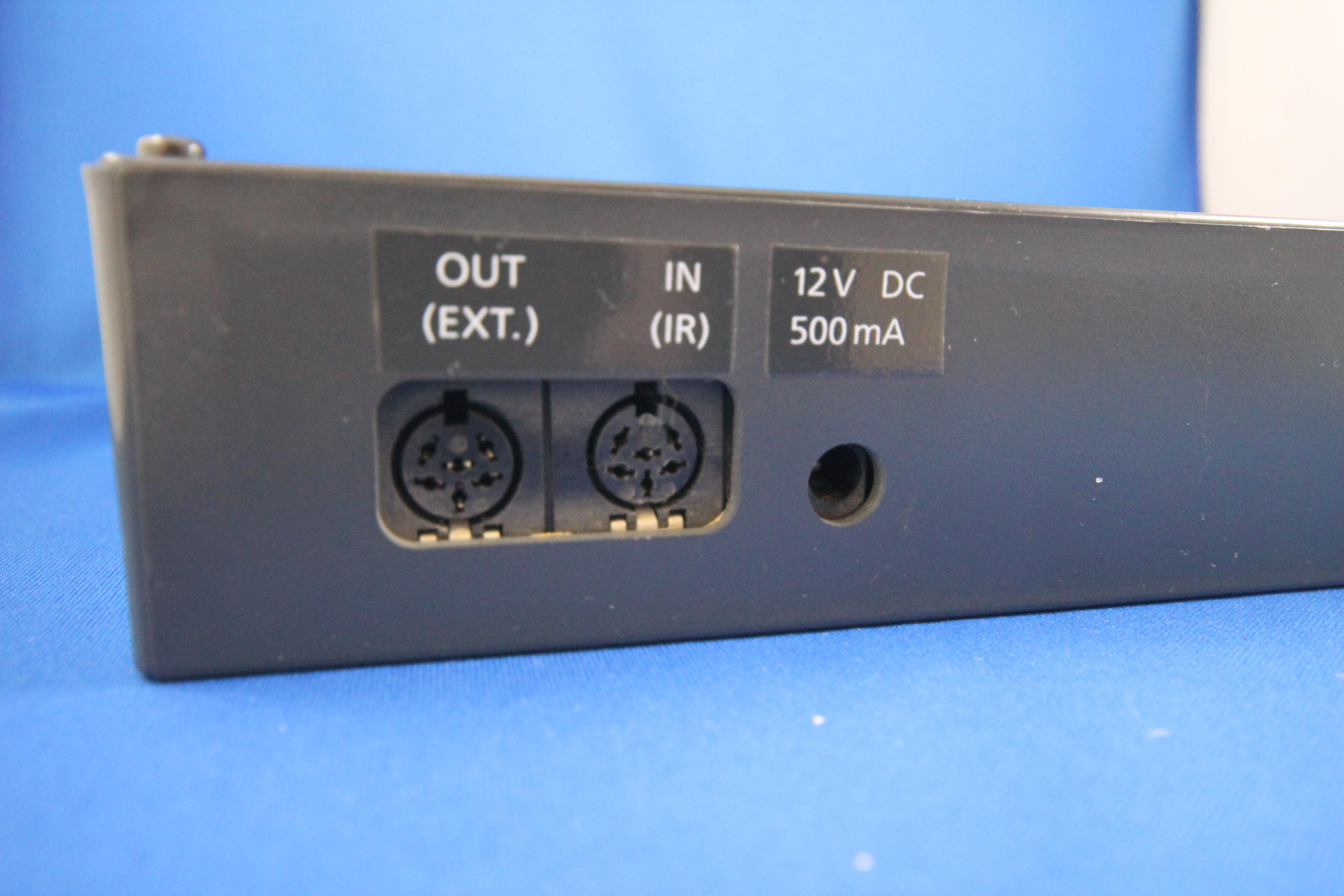
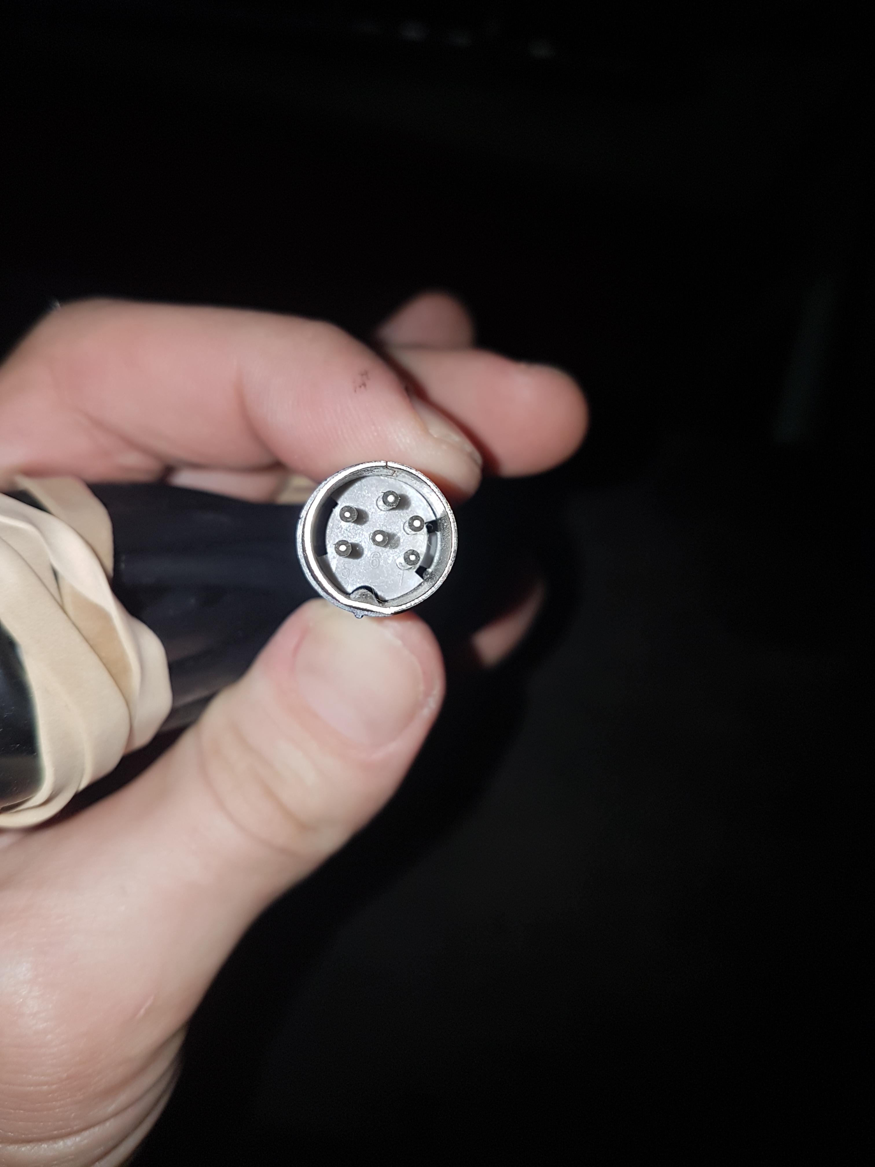
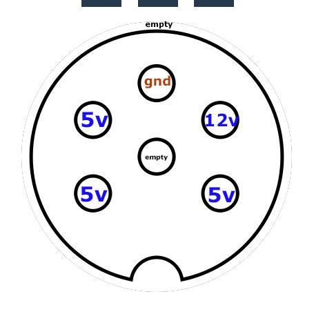
16 May 2022 at 15:12 #34826BlokkenpilootBRONZE MemberThanks! I found the +5v (and 12v) coming out of the “Loudspeaker Switch’ IR din”. Now i will trace the wiring to see if i can determine which pin should be “Data”
I attached the MCL IR EYEto the +5v and GND and the lights of the IR EYE did turn on, the Loudspeaker switch clicked a lot, and i was able to light up the “receiving” light on the MCL IR EYE when pressing buttons on a beolink 1000 remote.
Unfortionally the loudspeaker switch doesn’t do anything anymore. I’m not sure if it’s stuck on a channel until i press the right button, but i can’t… Dont know which one is the data cable or perhaps i accidentally shorted something, i don’t know and this is how far my expertise goes with this kind of equipment.
So it’s on eBay now, and until then, it’s a nice display piece in my room 🙂
Tested the voltage with an multimeter, didn’t think of that before:

@matador
And no worries about not being on topic, i think you are and probably help someone who looks here 🙂22 February 2025 at 23:09 #63950kirinBRONZE MemberHi Beo enthusiasts,
as I am just playing around with some toys (Beo4, IR sensors, arduino) I just have to revive this thread, as I found out that the wiring stated above seems not to be correct regarding the MCL IR receivers (I hope that is the correct „type“), it may be another at that VX sensor:
5V power supply – green
ground – brown
data – white
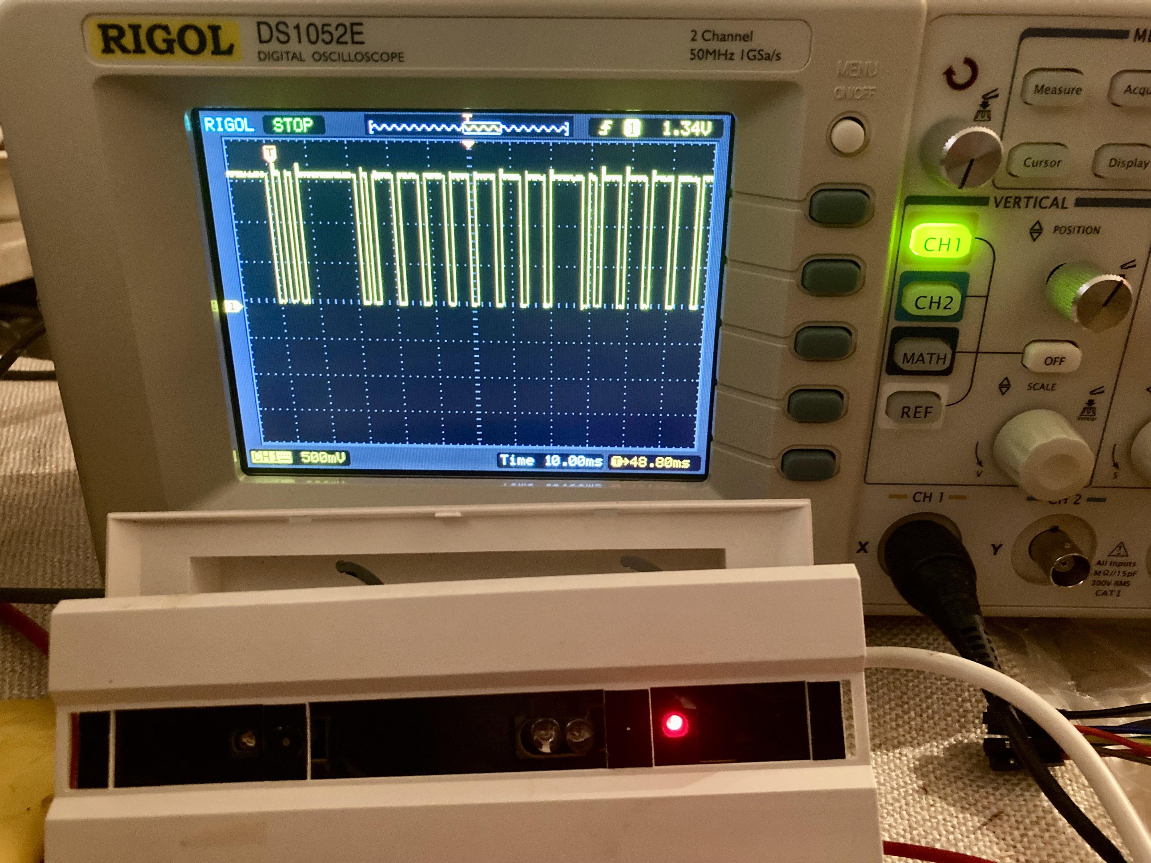
The white will emit data: the pulses are high to low with a voltage of ~1.5V (instead the 5V of more modern IR eyes)
Please see attached picture of the scope. I recorded a Beo4 signal, it is of course similar to the IR eye but, as written, delivering a lower voltage.
You can also see the used sensor.
23 February 2025 at 11:28 #63959MadskpGOLD Memberas I am just playing around with some toys (Beo4, IR sensors, arduino) I just have to revive this thread, as I found out that the wiring stated above seems not to be correct regarding the MCL IR receivers (I hope that is the correct „type“), it may be another at that VX sensor: 5V power supply – green ground – brown data – white
I can confirm the colors in regards to the rectangular MCL IR eye. In case of the MCL IR eyes you should be able to count on the wire colors being correct as the connection to MCL2A and MCL2AV is with srew terminals where the wire colors are printed on the PCB next to the screw terminals.
For the Newer round type IR eye where the conenction on the IR eye is with screew terminals the color coding can vary depending on the product type it is used with and wheether a twisted pair ethernet cables is used for it, so in case of these IR eye’s it is better to look up a wirering diagram than depend on the color coding. This might also apply to the VX sensor IR eye.
The white will emit data: the pulses are high to low with a voltage of ~1.5V (instead the 5V of more modern IR eyes)
That sounds odd as the IR data signals are compatible across the different IR eye’s as tested in this thread https://forum.beoworld.org/forums/topic/beolink-passive-ir-eye/
Location: Denmark
23 February 2025 at 12:46 #63963kirinBRONZE MemberHi Madskp,
I agree, you can see sonsor and signal on the picture, however, maybe I got a modified IR sensor.
I do own 3 others, which were sold together, I will check the others as well.
Best regards
23 February 2025 at 13:26 #63965MadskpGOLD MemberHi Madskp, I agree, you can see sonsor and signal on the picture, however, maybe I got a modified IR sensor. I do own 3 others, which were sold together, I will check the others as well. Best regards
If it is any help I can also try to check the signal on one of my MCL sensors with a logic analyzer. Maybe tomorrow
Location: Denmark
24 February 2025 at 18:41 #63994MadskpGOLD MemberI just did some testing with an MCL IR eye connected to a MCL2AV. WhatI see is a voltage drop from 4.97 V to ~3.68V depending on the command when pressing af key on the remote.
With the Ir disconnected I also measure 4,97V on the data screw terminal the MCL2AV, so must be that voltage the IR eye I trying to pull down.
Measuring on the IR eye without connection to the MCL2AV I see1.57V that is pulled down to ~1.3-1.4V depending on the command when pressing af key on the remote.
Hope this is usefull
Location: Denmark
27 February 2025 at 18:10 #64171kirinBRONZE MemberHi Madskp,
just to resolve this post by me, thanks for your response, btw! – I have tested the others;
I admit I forgot to state, that I put 5V as input to the brown (grd) and green (Vdd) cable, so I did not use the MCL2AV or any receiver at all and measured with respect to ground the output data on the white cable;
I got the same result (high:~1.65V, low ~0.1V) , I think it fits to your measurement inside the box.The good thing is, that it is quite easy to get cheap IR transmitters for any projects in that way – which was clear already in the posts by you 🙂
Best, kirin
-
AuthorPosts


- You must be logged in to reply to this topic.