


Home › Forums › General Discussion & Questions › General Discussion & Questions › Beosound 9000 IR repair, PCB 14.
- This topic has 8 replies, 4 voices, and was last updated 9 months, 3 weeks ago by
 bigbruggsy.
-
AuthorPosts
-
4 May 2024 at 12:50 #54527
 Moderator
Hi alls,
With all the hype around the 9000c, it seems our old units are back in the light again; thank you Recreated Department!
Well, mine is a MK2 and has IR troubles. I believe it’s “again” a matter of three capacitors.
But looking at the three service manuals, MK1, MK2 and MK3 and also to some pictures on the web, I’m unbale to see if the PCB14 is all SMD or may have those capacitors easy to replace.This unit is quite long to dismantle and that one has been a lot of time, I dont want to do it for nothing with the risk of breaking something just to discover the capacitors are beyond my skills to replace.
Anyone knows to what looks like the IR PCB in MK2 Beosound 9000?
Thanks.
Location: Paris France
4 May 2024 at 15:56 #54532 MadskpGOLD Member
Never had the opportunity to open a BS9000, so can’t comment on which type of capacitors is used.
But even though it might be SMD caps you should be able to replace these with “regular” caps (maybe lying down instead of standing) if space allows it on the PCB, and there is enough height available.
Guy had succes replacing SMD caps with regular caps on his BC2300 CD laser PCB. It was in my BS Ouverture repair thread, but for some reason that thread is not available right now .
Location: Denmark
4 May 2024 at 17:49 #54609Thanks Madskp,
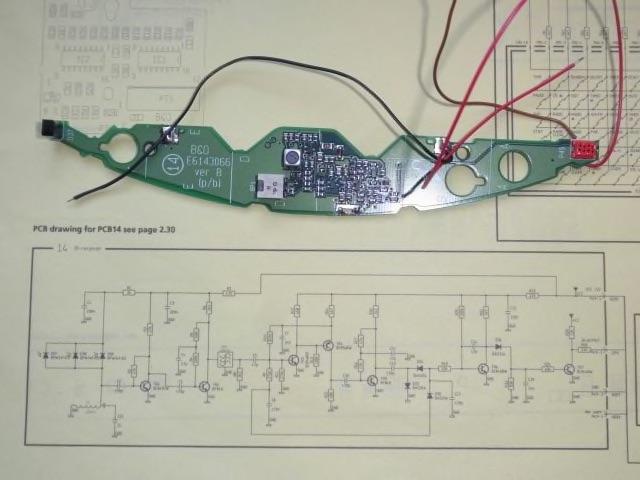
I did it on my Century IR board, yes. But the thing is I got this picture of the PCB 14 on the internet and I can’t see a capacitor I can replace on it.

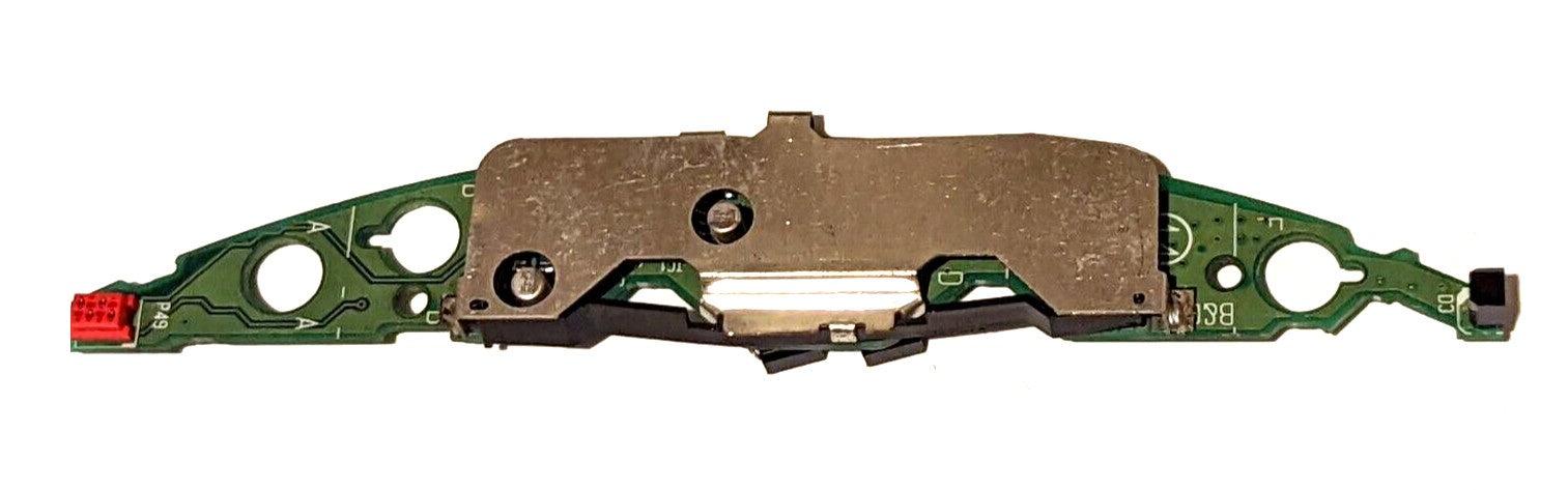
I can also find picture that PCB where the caps are easy to locate:

That’s why I’m asking if anyone knows which PCB is in the MK2 BS9000.
Location: Paris France
7 May 2024 at 15:50 #55347You need to replace these 2 SMD capacitors. The picture shows the wrong way of mounting the black plastic strip in front of it. It needs to be turned 180 degrees.
Location: Utrecht
14 May 2024 at 21:30 #55622Thank you Beobuddy,
The two pictures seems to show the same PCB. Looking at the red socket they look like shown from the same side and in the first I cant see any capacitor.
I dont know much about SMD electronics but What I fear is that it would exist some capacitor so tiny that it would be veru difficult to replace them.
Are all smd capacitors look like that little aluminium can or are they some that look like resistors, like very difficult to replace?
Location: Paris France
16 May 2024 at 16:09 #55674MadskpGOLD MemberA little input that might get you further.
The SMD electrolytic capacitors (canned style) are fairly easy to remove by twisting them with a pair of tweezer while at the same time pushing in against the PCB. With this method the legs will separate from the can, and the risk of ripping PCB traces are minimal. Afterwards the legs can be desoldered from the PCB.
Soldering in new SMD electrolytic cap on the other hand is a pain in the *** as the legs are underneath the cap, and there is almost no place to get the tip of a soldering iron in. I did it on my Ouverture laser PCB, but would go another way today.
The alternative could maybe be ceramic SMD caps. I have seen retro computer entuisiasts use them instead of electrolytic caps on old computer PCB’s.
What I dont know is if you would loose any properties of the electrolytic cap which might be essential in this circiut, and if you can get any in the correct value.
But the SMD ceramic cap would be far easier to solder on in my opinion
Location: Denmark
16 May 2024 at 16:41 #55675MadskpGOLD MemberThis video both show the removal method and he also use the ceramic caps as replacement for the electrolythics on a computer motherboard
https://youtu.be/rpVAg6hG__Y?si=U18MS1VSlTBMbZXc
Location: Denmark
12 December 2024 at 13:47 #61528Hi alls,
Just to confirm that the PCB14 in Beosound 9000 MK2 indeed looks like the picture above.
After replacing both 22 microfarad SMD capacitors with regular ones, the IR board calme back to life.
Thanks to everyone who helped.
Location: Paris France
23 September 2025 at 18:56 #69868bigbruggsyBRONZE MemberThank you for your post and update. I also have a problem with my Beosound 9000 not being able to respond to the remote (checked that its in the right “option”) My question is how do i remove this PCB?
-
AuthorPosts
- You must be logged in to reply to this topic.