Home › Forums › Product Discussion & Questions › BeoSound › Beosound 1 (CD version) data link???
- This topic has 47 replies, 7 voices, and was last updated 1 year, 11 months ago by
B3OHACK3R.
-
AuthorPosts
-
3 January 2024 at 10:14 #51707
 Moderator
I a pretty sure that the audio part will work, but more interesting if the data will. For one thing which commands should be used? But you could try something like Link + CD or AV + CD.
Yes I anticipate that the lack of Commands/Option Settings may be a constraint, but could be worth trying a few funny commands such as LINK and AV, so thanks for that.
Another thing is that it can only be set to option 0 or 1, so no way to select which is a link room. However if this is/was an attempt of a new type of link system, the role definition might not be the same as in the older systems
Yes I am struggling to think of a ‘use case’ where two BS1s (two audiomasters?) are connected in separate rooms, but it could be an interesting test nevertheless.
Perhaps we should try connecting the BS1’s Data + and Data – to a Masterlink device Data in/out (pins 1 and 2) and see what happens? If I am feeling brave I could try it with my BV10-32, but I wouldn’t know what to connect to the ‘ML sense’ pin 3.
Location: Warwickshire, UK
My B&O Icons:


 3 January 2024 at 10:31 #51708
Madskp
GOLD Memberbut it could be an interesting test nevertheless.
Indeed
Perhaps we should try connecting the BS1’s Data + and Data – to a Masterlink device Data in/out (pins 1 and 2) and see what happens? If I am feeling brave I could try it with my BV10-32, but I wouldn’t know what to connect to the ‘ML sense’ pin 3.
Maybe not a good idea as the Masterlink data is something like 0.25V and I measured 5V in one of the pins on my parents BS1. But maybe @B3OHACK3R can elaborate on that
Location: Denmark
3 January 2024 at 10:39 #51709 Moderator
Maybe not a good idea as the Masterlink data is something like 0.25V
Good point! I will hold back from that!
One other thought: My original BeoSound 1 (used for tests) is at SW version 1.3, and my newer one at SW1.4. I think that the later BS1s (with built in clock) have SW versions 2.X. – I doubt that there are any differences and if anything B&O would probably reduce any link capability in the newer versions. Any idea of your parents’ BS1 SW version?
Location: Warwickshire, UK
My B&O Icons:


 3 January 2024 at 11:02 #51710
Madskp
GOLD MemberAny idea of your parents’ BS1 SW version?No, did not check that. Will do next time I am there.You can also try to measure voltage on pin 6 and 7 on your devices just to see if you also have the 5V on pin 6Location: Denmark
3 January 2024 at 11:32 #51711B3OHACK3R
BRONZE MemberMy best guess as also noted in the Beolink Active thread is for use with the ML/MCL converter where powerlink to MCL is also possible as shown in the ML/MCL user manual. For this sceneario commands from the link rooms has to be recieved through the Power Link connection.
Ah, true. You mentioned it there already. It makes certainly sense. Probably they had plans to implement it everywhere but then stopped. On several products you can see that they had something in mind with PL-Rx but then didn’t implement it properly.
My other guess was that speakers with buttons or volume dials were planned but then never developed. I guess we will never find out.3 January 2024 at 11:43 #51712B3OHACK3R
BRONZE MemberMaybe not a good idea as the Masterlink data is something like 0.25V and I measured 5V in one of the pins on my parents BS1. But maybe @B3OHACK3R can elaborate on that
Perhaps we should try connecting the BS1’s Data + and Data – to a Masterlink device Data in/out (pins 1 and 2) and see what happens? If I am feeling brave I could try it with my BV10-32, but I wouldn’t know what to connect to the ‘ML sense’ pin 3.
No, please don’t do that. As Madskp wrote ML requires a special receiver and transmitter circuit operating at low voltages +/- 0.25 V. It’s definitely not available in the BS1 according to the service manual.
My best guess is that it’s an exposed serial port of the microcontroller. Either use an oscilloscope or a logic analyser to see if something is coming out there. If it’s valid serial data then you could talk to it with something like the FTDI TTL-234X-5V.
3 January 2024 at 12:02 #51713 Moderator
No, please don’t do that. As Madskp wrote ML requires a special receiver and transmitter circuit operating at low voltages +/- 0.25 V. It’s definitely not available in the BS1 according to the service manual. My best guess is that it’s an exposed serial port of the microcontroller. Either use an oscilloscope or a logic analyser to see if something is coming out there. If it’s valid serial data then you could talk to it with something like the FTDI TTL-234X-5V.
Thanks for advice @B3OHACK3R! I will leave that thought alone and start saving for an oscilloscope!
Location: Warwickshire, UK
My B&O Icons:


 3 January 2024 at 12:19 #51714
B3OHACK3R
BRONZE MemberThanks for advice @B3OHACK3R! I will leave that thought alone and start saving for an oscilloscope!
There are some pretty inexpensive logic analysers available. Search on Amazon for 8CH logic analyser. Should be more than enough for anything that might get send on the Data Out pin.
3 January 2024 at 12:31 #51715Madskp
GOLD MemberThere are some pretty inexpensive logic analysers available. Search on Amazon for 8CH logic analyser. Should be more than enough for anything that might get send on the Data Out pin.
Found one on Ebay and ordered it. Should be nice to have for things like this
Location: Denmark
3 January 2024 at 16:06 #51716B3OHACK3R
BRONZE MemberFound one on Ebay and ordered it. Should be nice to have for things like this
Nice! I think most of these cheap ones still work with the Saleae application. It’s a straight forward to use tool.
3 January 2024 at 16:11 #51717 Moderator
You can also try to measure voltage on pin 6 and 7 on your devices just to see if you also have the 5V on pin 6
I just checked – same results for me (exactly as in your first post).
It’s a shame that the 5V is always there, not just when turned on, as that could have been useful.
Also, it would be quite useful to be able to turn the BS1 on via the AUX input, for instance when I start airplaying to a connected Airport Express.
Location: Warwickshire, UK
My B&O Icons:


 3 January 2024 at 16:32 #51718
Madskp
GOLD MemberFound one on Ebay and ordered it. Should be nice to have for things like this
Nice! I think most of these cheap ones still work with the Saleae application. It’s a straight forward to use tool.
Looking forward to get my hands dirty on some datalink ?
You can also try to measure voltage on pin 6 and 7 on your devices just to see if you also have the 5V on pin 6
I just checked – same results for me (exactly as in your first post).
Ok so at least consistent results
Location: Denmark
20 January 2024 at 12:29 #51719Madskp
GOLD MemberMadskp wrote: Found one on Ebay and ordered it. Should be nice to have for things like this Nice! I think most of these cheap ones still work with the Saleae application. It’s a straight forward to use tool.
I have got one now and it is working with the Saleae application with the excaption of the channel naming on device being 1-8 and ind the applicattion being 0-7, but I think I can mange that.
I wan’t to be comfortable using it before I am visiting my parents again next weekend and doing measurements on their BS1.
Therefor I have done some testing with different data sources, and can see that I might need some verification of what I am doing.
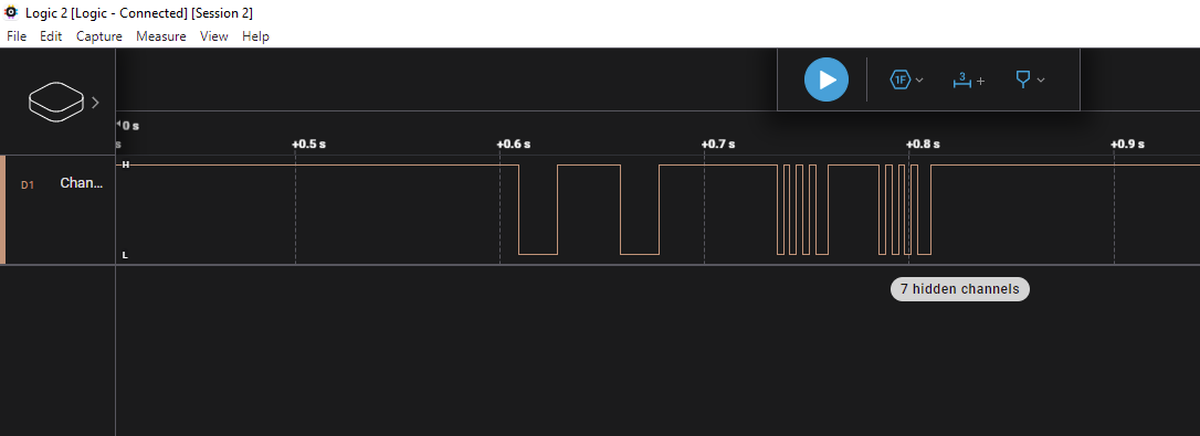
I have taken this screenshot from a recording of an A.TAPE command on the tape port on a MCL2AV:
What I need to know is does this look correct, or do I need to do some settings in the Saleae application?
Also if I export the data in binary format what is the best way to compare them to those datalink commands that are available in different online projects?
I have found a HEX editor, but unsure what format I must show the data in to be compareable (BInary, HEX, Decimal ??)
Thanks in advance
Location: Denmark
20 January 2024 at 17:29 #51720B3OHACK3R
BRONZE MemberNice, that’s looking good to me. You captured a DL80 message. They are pretty short and I think there is no public documentation about it so far. The shorter pulse is a logic 0, the longer one a logic 1. That’s all you need I guess. The two longer pulses right in the beginning might be some kind of message header or wake up mechanism.
FYI – DL86 also implements a third value “same bit as before”. This pulse then is a bit longer than a logic 0 but shorter than a logic 1. I think DL80 doesn’t have that.How I understood it, for a source activation DL80 will send out 2x 4 bits with the same value. For PHONO I have seen 0011 + 0011 and what you are seeing is likely 0001 + 0001 for A.TAPE. I think that does only partly correlate with DL86 / MCL. There e.g. 0x91 is the A.TAPE source which is 1001 0001 in binary. So the last 4 bits are still matching. Same is true for the PHONO source.
So for CD activation on DL80 I would expect seeing 0010 + 0010.20 January 2024 at 18:39 #51721FYI:
A few years ago, a Norwegian by the name of Tore Sinding Bekkedal tried to reverse-engineer the Datalink protocols. Tore wrote the logic analyzer software for Arduino. You can see his efforts on this GitHub page: https://github.com/toresbe/datalinkLocation: Norway
My B&O Icons:
 20 January 2024 at 23:28 #51722
pilatomic
SILVER MemberWhat I need to know is does this look correct, or do I need to do some settings in the Saleae application? Also if I export the data in binary format what is the best way to compare them to those datalink commands that are available in different online projects? I have found a HEX editor, but unsure what format I must show the data in to be compareable (BInary, HEX, Decimal ??) Thanks in advance
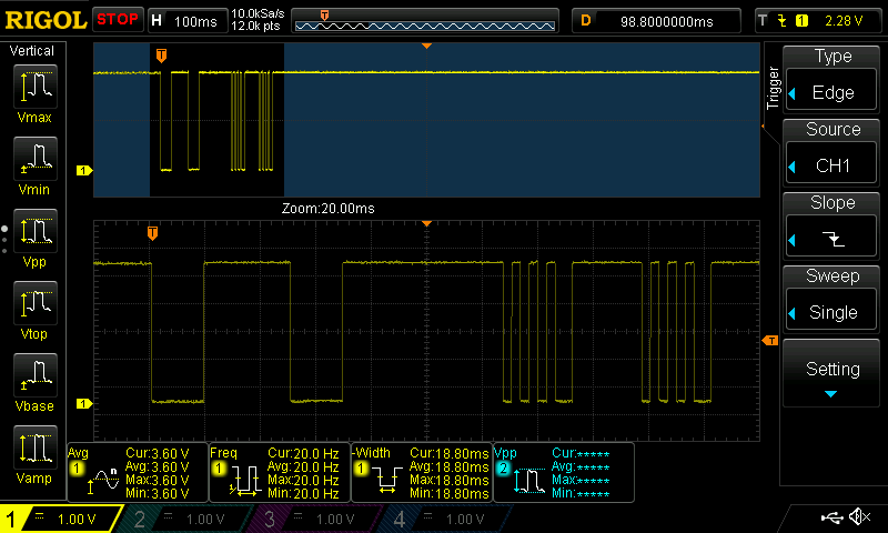
This look totally correct, here is a scope capture of out of the TAPE2 socket on my Beomaster 5500, from a few years ago.
I have successfully reverse engineered most of the DL-80 protocol, but my notes really need a good cleanup to be of use (It’s mostly a pile of different files, scope captures, logic analyzer traces, etc…)
I do believe the 2 pulses are either a compatibility mode for older devices (I think I read somewhere that some pre-datalink devices used double pulses to trigger play / pause), or a way to trigger a collision on the bus and get the end device to stop talking and listen.
What you have following that is definitely the “Beocord play” command, so I think you’re all set up.
B3OHACK3R : Don’t reason with the pulse length for the DL-80, it’s simply made of 8 bits packets with 3.125ms bit duration.
Location: France
My B&O Icons:
 21 January 2024 at 11:29 #51723
Madskp
GOLD MemberHello guys and thanks for all the inputs.
Glad to hear that I am on the right track.
Now I will try with some different commands and see if I fully understand it.
Location: Denmark
21 January 2024 at 13:13 #51724B3OHACK3R
BRONZE MemberB3OHACK3R : Don’t reason with the pulse length for the DL-80, it’s simply made of 8 bits packets with 3.125ms bit duration.
Ah, interesting. You probably have more insight into the DL80 stuff than I currently have.
How are you counting those 8 bits?
So in your capture from above – are you seeing two bytes each being 01010100?
From my experience with DL86 (and IR as well) there a logic 0 is a 3.125 ms pulse. Logic 1 is a 9.375 ms one while “same bit” is a 6.250 ms pulse.21 January 2024 at 16:11 #51725pilatomic
SILVER MemberB3OHACK3R wrote:
How are you counting those 8 bits?
So in your capture from above – are you seeing two bytes each being 01010100?Exactly ! Although I have the bit values inverted in my notes, since the bus is pulled to 5V through a resistor, and actively pulled low by the end devices, so I use ‘1’ when the bus level is 0V.
In its simplest form, all commands begin and end with a low bit (so they are effectively 6 bits left for the command), and are transmitted twice with an 8 bit pause in between. As the controlled devices became more complex, so did the protocol, and eventually it grew up into quite a bag of knots (French expression, but I think it should convey its meaning well enough).
The live status featured on the beosystem 5500 for example breaks both those rules, but still manages compatibility with older devices ! I’m quite impressed actually, I don’t know what the software tools were in 1986, but making that protocol work back then could not have been an easy task !
Location: France
My B&O Icons:
 21 January 2024 at 17:24 #51726
B3OHACK3R
BRONZE MemberExactly ! Although I have the bit values inverted in my notes, since the bus is pulled to 5V through a resistor, and actively pulled low by the end devices, so I use ‘1’ when the bus level is 0V.
Interesting. It totally makes sense by just looking at it.
Nevertheless if you are coming from DL86 where data is determined by the pulse length its a bit different and still makes sense somehow.Your capture is an ATAPE activation command. In the MCL world (and ML as well) that is the 0x91 command. 1001 0001 in binary.
Similar commands are CD (0x92) and PHONO (0x93). So the first four bits are likely some kind of a category (audio in that case) and the last four are the actual source.
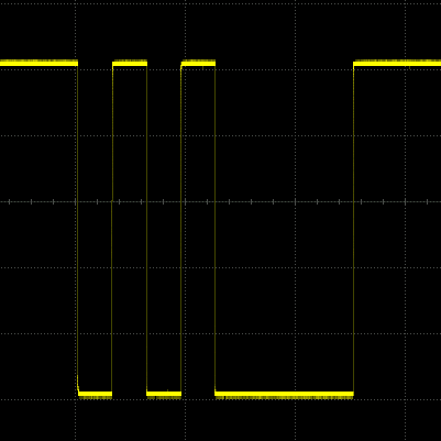
So if you just look at the last 4 bits and take the DL86 pulse length decoding it matches the DL80 ones just fine.So going back to your example again. With that pulse length decoding strategy you’ll have 3x short pulse and 1x long pulse. Resulting in 0001.
For PHONO activation I have seen the one below and interpreted it as 0011 which then would match the last 4 bits of DL86 for that source (0x93 = 1001 0011). My conclusion from this was that DL80 does not send a “space” between “1”s like DL86 does. It just ties them together resulting in that long low period for the two sequential “1” bits.
Of course I was really biased with the DL86 stuff and you weren’t. So I could be completely wrong.
Yes, building all that must have been “interesting” back in those days.
-
AuthorPosts
- You must be logged in to reply to this topic.


