


Home › Forums › Product Discussion & Questions › BeoMaster › Beomaster 901 – missing left channel – **FIXED**
- This topic has 1 reply, 1 voice, and was last updated 2 years, 3 months ago by
 HatOfTheCat.
-
AuthorPosts
-
7 April 2024 at 09:13 #54166
 HatOfTheCatBRONZE Member
Having managed to restore one 901 I foolishly acquired another broken pony. This one has no sound from left channel. Its all original inside and no signs of leaking or burst capacitors.
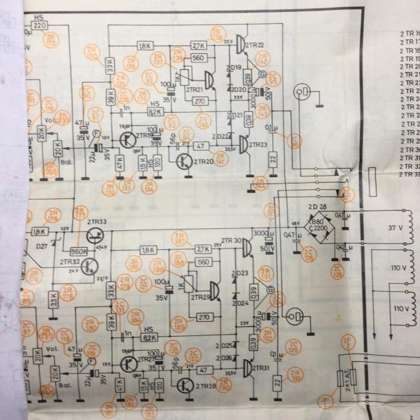
Before buying fresh capacitors etc. I want to see if I can get the LEFT channel working at all. I’ve had a check through the components and first transistor TR19 (see schematic of power amplifier stage below) had an hFE that was on life support so have replaced that and also the bias transistor TR21 as the legs all but fell off when I removed it to test it (it was okay ), about five resistors were well out of spec so have replaced them too. None of the above has made the left channel work. Measuring the bias voltage across resistor R142 at Emitter of TR22 output transistor gives reading of zero mV and does not change when turning the variable resistor R137 (to adjust as per the service manual) so looks like TR22 is dead as base & collector voltages around it are correct. Right channel looks fine as regards the bias (I’ve turned them both down to minimum for now to avoid risk of being too high on powering up without dim bulb to limit current).
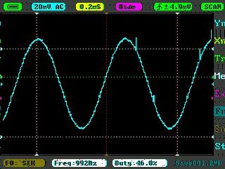
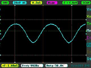
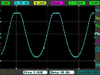
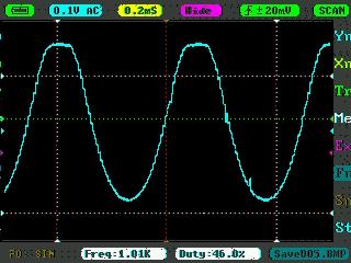
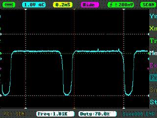
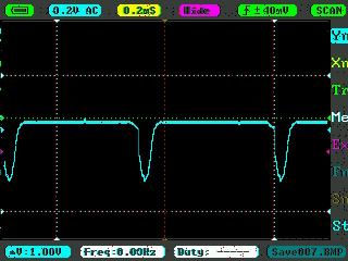
I’ve used my pocket oscilloscope to capture the signal at various points. With TR20 removed from the board (tested okay on pocket tester for hFE etc.), the signals all round TR19 were clean sine waves. Is the top clipped waveform simply due to TR22 being dead ?? Checking it with multimeter in circuit it doesn’t appear shorted. As I said I haven’t replaced any capacitors yet but I’ve measured all the ones in this part of the board (off the board) and all have capacitance at or above their rating (have just acquired a better capacitor tester late today that will give a guideline ESR, have only tested C92 with it so far but that came out as 0.15 Ohms so that one at least looks fine).
Any ideas and test procedures appreciated ! I’m powering up via dim bulb only for now as want to avoid any possible short caused by me destroying anything. Also the 901 I restored before was later version of the model with different output transistors which were mounted on opposite side of the board to rest of the components and just screwed on to the heatsink, this one has them on same side as rest of the components but with a black metal bar holding them sandwiched against the heatsink, how do I actually take that apart so I can get to the transistors to test them out of circuit and/or replace as required ?? Pic of schematic is later one which just has different value resistors either side of the bias transistor (are both 820 Ohms on this one).

Tr19 – Base

TR19 Emitter
Tr19 Collector
TR20 Base
TR20 Collector
T22 Emitter
8 April 2024 at 19:22 #54167HatOfTheCatBRONZE MemberFIXED – cracked solder joint on emitter of the TR22 output transistor (BD697 type). The heat sink on this model is held onto the metal frame of the case by just two screws, one at each end of which the one at the left end was missing (the end where the TR22 is right by). The output transistors are held in place each with a screw that goes through the heat sink, through the transistor and into a brass threaded insert on a bar on the inside that spans them all effectively sandwiching them to the heatsink (bit overkill). So any movement in the heatsink will push on the transistors and flex their solder joints to the PCB. I didn’t see it until I started looking at how to remove the heatsink then saw it wasn’t fully attached. Moving it a little made the crack in the solder open enough to see (under the layer of dust, I should have cleaned it before starting work as I did have a look at the joints first off). Reflowed it and the others for that transistor and inspected the others and hey presto left channel working 🙂 Annoyingly reflowing all the output transistor joints was first thing I did trying to fix the last one, but I thought “hey there’s a massive bar thing holding them firmly… they won’t have been moved about”.
-
AuthorPosts
- You must be logged in to reply to this topic.