






Home › Forums › Product Discussion & Questions › BeoMaster › Beomaster 5000 output stage overheating plus left channel is quiet
- This topic has 3 replies, 3 voices, and was last updated 3 months, 4 weeks ago by


-
AuthorPosts
-
9 June 2026 at 14:42 #123972
 Andy NewlandsBRONZE Member
Hi, all.
I’m new here, so please let me know if I’m posting in the wrong place or made some other fundamental error.
I have 2 problems with my Beomaster 5000 (type 2322):
- The output transistors/heatsink get very hot after just a couple of minutes, from switch on, with no load.
- With speakers connected, and an audio source connected, the left channel seems very quiet (the right seems “OK”)
With no-load, and measuring with a cheap IR thermometer, the transistors quickly exceed 40 degrees C. This surprises me. I daren’t risk leaving the unit powered up for any longer after that, in case I do more damage.
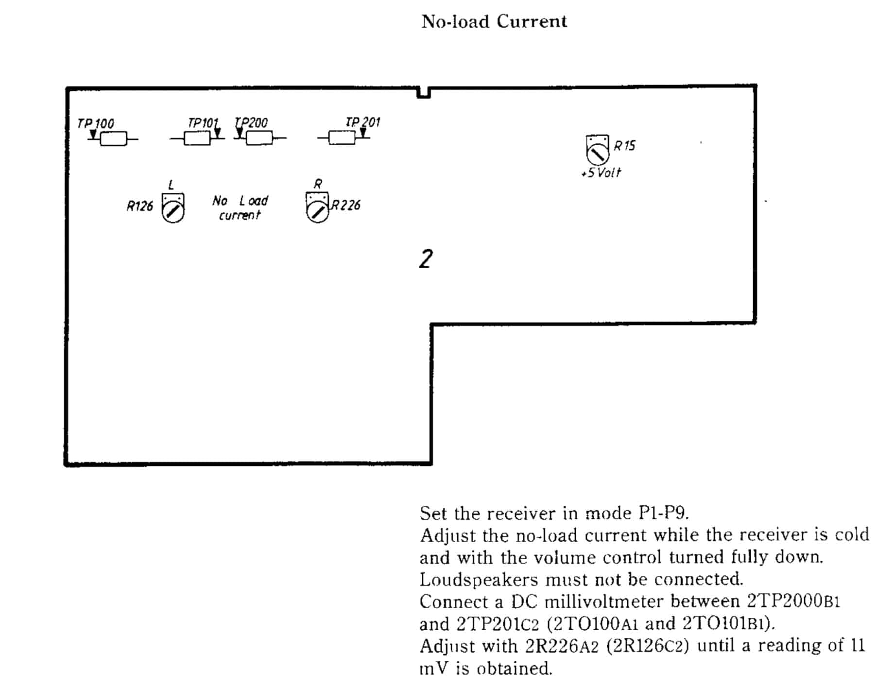
I tried following the setup/trim recommendations from a (blurry) photocopied service manual I found on line, as follows:
Set the receiver in mode P1-P9.
Adjust the no-load current while the receiver is cold and with the volume control turned fully down.
Loudspeakers must not be connected.
Connect a DC millivoltmeter between 2TP2000B1 and 2TP201C2 (2TO100A1 and 2TO101B1).
Adjust with 2R226A2 (2R126C2) until a reading of 11 mV is obtained.The trimpots appear to be 100 ohms (with one leg tied to the wiper?) and resistance varies, as I’d expect, when the wiper is turned. However, I’m reading 42V (that’s VOLTS – not milli-volts) and, intermittently NO VOLTS, between the measurement points, specified above. I cannot get near the specified 11mV, no matter where I set the trimpots. The fact I get OK sound out, with speakers connected, from both the tuner and tape deck (and, until it died couple days ago, the CD player) – albeit with a quiet left-channel – makes me think the unit is basically OK. Question: in the above text, does 2TO100A1 and 2TO101B1 actually mean 2TO100B1 and 2TO101C1, or 2TO100C1 and 2TO101B1 ?
I’m pretty sure this used to work fine. It’s been stored for around a decade, so my thought was “maybe dried up electrolytics”, BUT I simply don’t know where to start diagnosing the problem(s)! I have a basic understanding of electronics and am quite happy swapping out components, and making adjustments, but I don’t want to start randomly swapping stuff out (I’ll end up causing more damage, I’m sure).
BTW: I have been through quite a few older posts which mention the overheating issue, but I’m not sure if/how these relate to my issue(s).
If anyone has experience and/or wisdom they’d care to kindly share with me, as to how I might approach this, I’d be very grateful.
Many thanks, in advance.
Kind regards
Andy
-
This topic was modified 4 months, 1 week ago by Andy Newlands.
My B&O Icons:
 25 June 2026 at 10:04 #124122Andy NewlandsBRONZE Member
Hi, again.
After a couple of weeks, I appear to have no replies. Can someone please let me know if this is because I have posted inappropriately (I’m new here), or if they think this is a “rare” or “difficult-to-solve” problem?
Many thanks
Andy
My B&O Icons:
25 June 2026 at 15:33 #124126Hi.
Nothing wrong with your post, just a quieter time at the forums.
The issue sounds very likely to be the no-load (idle) current. Those open-case pots might as well be bad, but supposing they still work, I read the service manual’s instructions like this:
- To adjust the right-channel no-load current you measure/place your multimeter probes at the ends of the TP200 and TP201, at the outer ends where the arrows point. There you should measure the 11mV, set by the trimmer R226.
- Then for the left-channel, it’s the same but TP100 and TP101 and the pot R126.
There are voltages of about 40V elsewhere around the amp stages.
Note: I do not have a BM5000 myself, and this is purely suggestion on how I would read the manual, which is somewhat cryptic about the points. It also has at least one type (“2TP2000B1” which I take should be 2TP200B1).
For comparison, here is a BM5500 being adjusted (the pic above the text “The trimmers were adjusted so the voltage reading across the emitter resistors of the channel measured 11 millivolts DC”): https://beolover.blogspot.com/2023/10/beomaster-5500-type-2333-reassembly-and.html
You’ll really want to have steady hand OR preferably a multimeter leads with those clips, as you don’t want to be poking around the live amp and have a probe slip and short something!
Location: Helsinki - Finland
My B&O Icons:
26 June 2026 at 12:55 #124178As above, definitely use clips on the meter leads. Even if you try and hold them steady, one will slip, it will short out something, there will be a reasonably sized “bang” and your Beomaster will no longer work.
Ask me how I know this… 😁
-
AuthorPosts






- You must be logged in to reply to this topic.