


Home › Forums › Product Discussion & Questions › BeoLink › Beolink 5000 repair
- This topic has 15 replies, 5 voices, and was last updated 2 months, 1 week ago by
 Madskp.
-
AuthorPosts
-
27 December 2025 at 13:13 #72109
 MadskpGOLD Member
I have aquired 2 Beolink 5000 remotes in different conditions.
They both seem to work for one way remote control, but both give the no contact text when I try to control a Beocenter 2500 or a MCL2AV.
The display on one of the is working, although a little dim, and the other one has missing lines plus an artifact of some kind above the text.
Both displays are no longer attached to the body of the remotes. Guess the glue is no longer working.
So a few questions here before I begin doing any repairs.
- I have read that the missing two way should be due to failing capacitors on the lower PCB. However I have not seen any description as to if is only one or all of them that will need replacing?
- Except for the capacitor replacing could there be any other issues affecting two way operation (I have done the setup two make sure they are set to two way)?
- Any kind of recommandations for a glue type to reattach the display?
- Can anything be to to the dim display?
- Is the artefact on the other display fixable at all?
- Any good tips as to how to secure the working display while working on the remotes?
My plan is to get one working remote out of the two, so will probably start to disassemble one of the and recap the PCB and repaint the casing, and then use those parts for the one with working display
Thanks in advance
Location: Denmark
27 December 2025 at 17:29 #72117Will be curious to see any photos you might be able to take! I’ve just hand-delivered my US-market BL5000 to Steffen in Copenhagen for his specialized repair service. Luckily mine was only missing a few pixel rows; I was a bit nervous about opening it up in case I caused more damage…
Location: Silicon Valley
My B&O Icons:
 27 December 2025 at 19:00 #72125
My plan is to get one working remote out of the two
If both display are likely working it is more than the majority of BL5000 still in use (got one myself without display) and both will deserve proper repair.
I can’t help regarding capacitors but you might find help searching BWI or BWII.
About the display: you may wait for a confirmation from any other member but when I was still believing my faulty display was from bad soldier join, I bought a T soldier tip fitted with some sort of rubber, made to secure the kind of bond that link the remote to the display. It was pretty cheap so maybe trying it would help someway. In my case it was the ribbon cable that was broken so the tool was of no use.
Good luck.
Location: Paris France
28 December 2025 at 07:43 #72129MadskpGOLD MemberWill be curious to see any photos you might be able to take! I
I will take some pictures along the way and share here.
I’ve just hand-delivered my US-market BL5000 to Steffen in Copenhagen for his specialized repair service. Luckily mine was only missing a few pixel rows;
I was also wondering if that was the way to go, but since one of the displays is not missing lines, I will start looking at it myself, knowing that there is a risk of damaging the display cable.
If both display are likely working it is more than the majority of BL500O still in use (got one myself without display) and both will deserve proper repair.
Only one of the is without missing lines, but dim, so better than not working, but not perfect.
About the display: you may wait for a confirmation from any other member but when I was still believing my faulty display was from bad soldier join I bought a T soldier tip fitted with some sort of rubber, made to secure the kind of bond that link the remote to the display. It was pretty cheap so maybe trying it would help someway. In my case it was the ribbon cable that was broken so the tool was of no use.
Thanks for sharing that info. I belive that is also how the forums user Steffen is fixing these, but with a new cable.
I can’t help regarding capacitors but you might find help searching BWI or BWII.
I will go on a search hunt, and share relevant links in this thread
Location: Denmark
28 December 2025 at 09:45 #72135I’ve repaired +20 BL5K lately and my experience is that the original display ribbon will fail at some point.
There is a guy in Struer I use my self who can replace the ribbon. PM me for contact details if you go down that route.
But if you chooses not to I think that Beolover has an instruction with a 3D printed fixture.For recap of the IR PCB, there is a guide from Leslie Nelwan at the Beoworld archive showing which caps there needs to be replaced.
https://archivedforum2.beoworld.org/forums/p/9016/89901.aspx
Look a little more than half way down.For reattach the display I use double-sided tape from RS Component after a good clean to remove the old glue.
https://dk.rs-online.com/web/p/skumtape-dobbeltsidet/1612919?gb=sThe artefact on the display is not fixable. At least for now.
In according to the service manual the only thing there can be ajusted is the contrast of the display.
Hope the above gives you some help and mybe you could get some inspiration for this:
https://forum.beoworld.org/forums/topic/beolink-5000-finally-a-solution//steffen
My B&O Icons:
28 December 2025 at 17:35 #72143MadskpGOLD MemberThank you very much for your insights SteffenI’ve repaired +20 BL5K lately and my experience is that the original display ribbon will fail at some point.
There is a guy in Struer I use my self who can replace the ribbon. PM me for contact details if you go down that route.I’ll send you a PM for details, as that might be nesesary at one point in the procces or if I choose to get both working.
For recap of the IR PCB, there is a guide from Leslie Nelwan at the Beoworld archive showing which caps there needs to be replaced.
https://archivedforum2.beoworld.org/forums/p/9016/89901.aspx
Look a little more than half way down.That’s great. And even greater I have all caps in stock since I bought replacements for my Beolink 7000 remote (although that did not fix 2 way on that). So might be faster that I thought to get going at recapping one of the boards.
For reattach the display I use double-sided tape from RS Component after a good clean to remove the old glue.
https://dk.rs-online.com/web/p/skumtape-dobbeltsidet/1612919?gb=sNice, I guess different types of double sided tape can be used, but great to have a known working product for reference.
The artefact on the display is not fixable. At least for now.
Thought so. It not that visible on the display without missing lines, only when seen in certain angles, so I can live with that.
The other one however has a large visible area of artefacts, so that might be the deciding factor for getting the connection to the display fixed or not.
In according to the service manual the only thing there can be ajusted is the contrast of the display.
Ahh yes thanks. I will try that to see if that can help on the visibility of the display 🙂
Hope the above gives you some help and mybe you could get some inspiration for this:
https://forum.beoworld.org/forums/topic/beolink-5000-finally-a-solution/Indeed very helpfull input, and thanks again. Very apriciated 🙂
Location: Denmark
29 December 2025 at 12:30 #72158For recap of the IR PCB, there is a guide from Leslie Nelwan at the Beoworld archive showing which caps there needs to be replaced.
https://archivedforum2.beoworld.org/forums/p/9016/89901.aspx
Look a little more than half way down.When I replaced the capacitors in one of my BL5000s several years ago I found Leslie’s post very useful, especially for the capacitor values. I also made use of the photos from a 2010 post by ‘MartinM’ here: https://archivedforum.beoworld.org/forums/t/35123.aspx
The photos are no longer attached, but I kept a copy – see below:
Location: Warwickshire, UK
My B&O Icons:
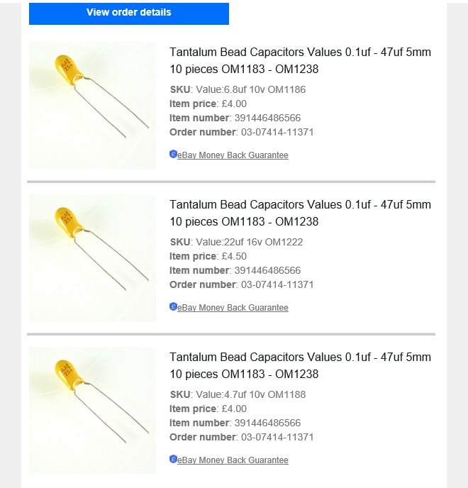
29 December 2025 at 12:43 #72160Just to add to the above, like MartinM I went for tantalum bead throughout – see my order below:
Location: Warwickshire, UK
My B&O Icons:
29 December 2025 at 12:44 #72161MadskpGOLD Memberskolesen wrote:
For recap of the IR PCB, there is a guide from Leslie Nelwan at the Beoworld archive showing which caps there needs to be replaced.
https://archivedforum2.beoworld.org/forums/p/9016/89901.aspx
Look a little more than half way down.
When I replaced the capacitors in one of my BL5000s several years ago I found Leslie’s post very useful, especially for the capacitor values. I also made use of the photos from a 2010 post by ‘MartinM’ here: https://archivedforum.beoworld.org/forums/t/35123.aspxThe photos are no longer attached, but I kept a copy – see below:
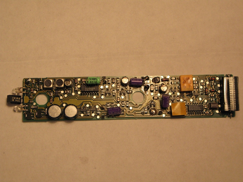
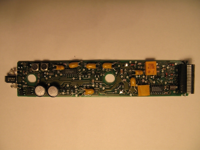
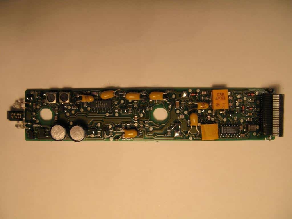
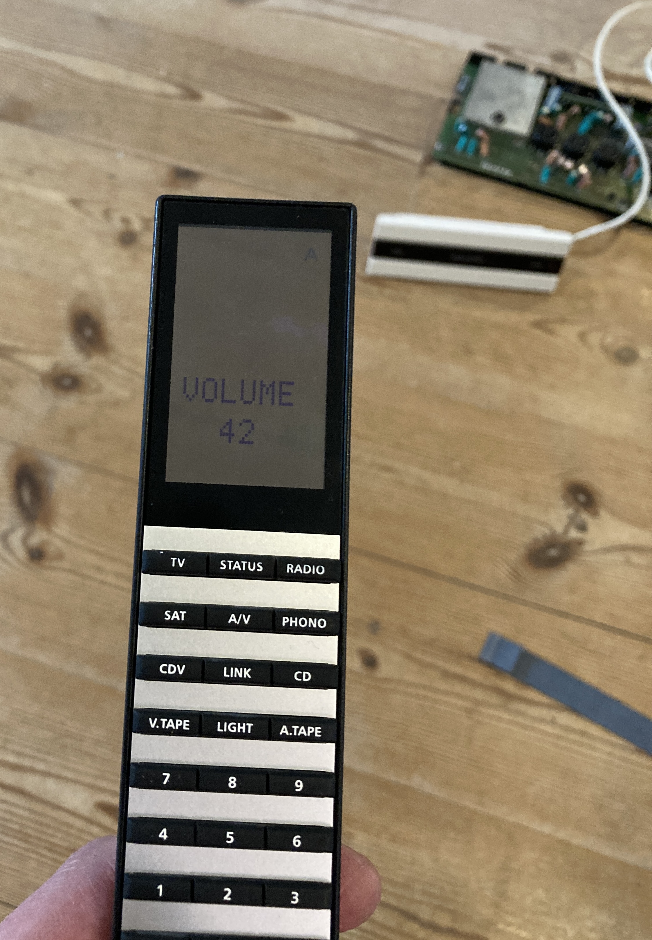
Thank you very much for that extra input and pictures. I looks like some replacements are made with tantylum capacitors instead of Elctrolytic. Not sure if it should make any difference. I Have started recapping the Beolink 5000 with missing lines in the display and are using electrolytic capacitors.
For some reason I do not seem to be able to insert pictures right now thought so have attached pictures with before and after replacing capacitors.
After recapping 2 way is working fine with both my Beocenter 2500 and a MCL2AV as shown on the attached picture where the volume is shown in the display.
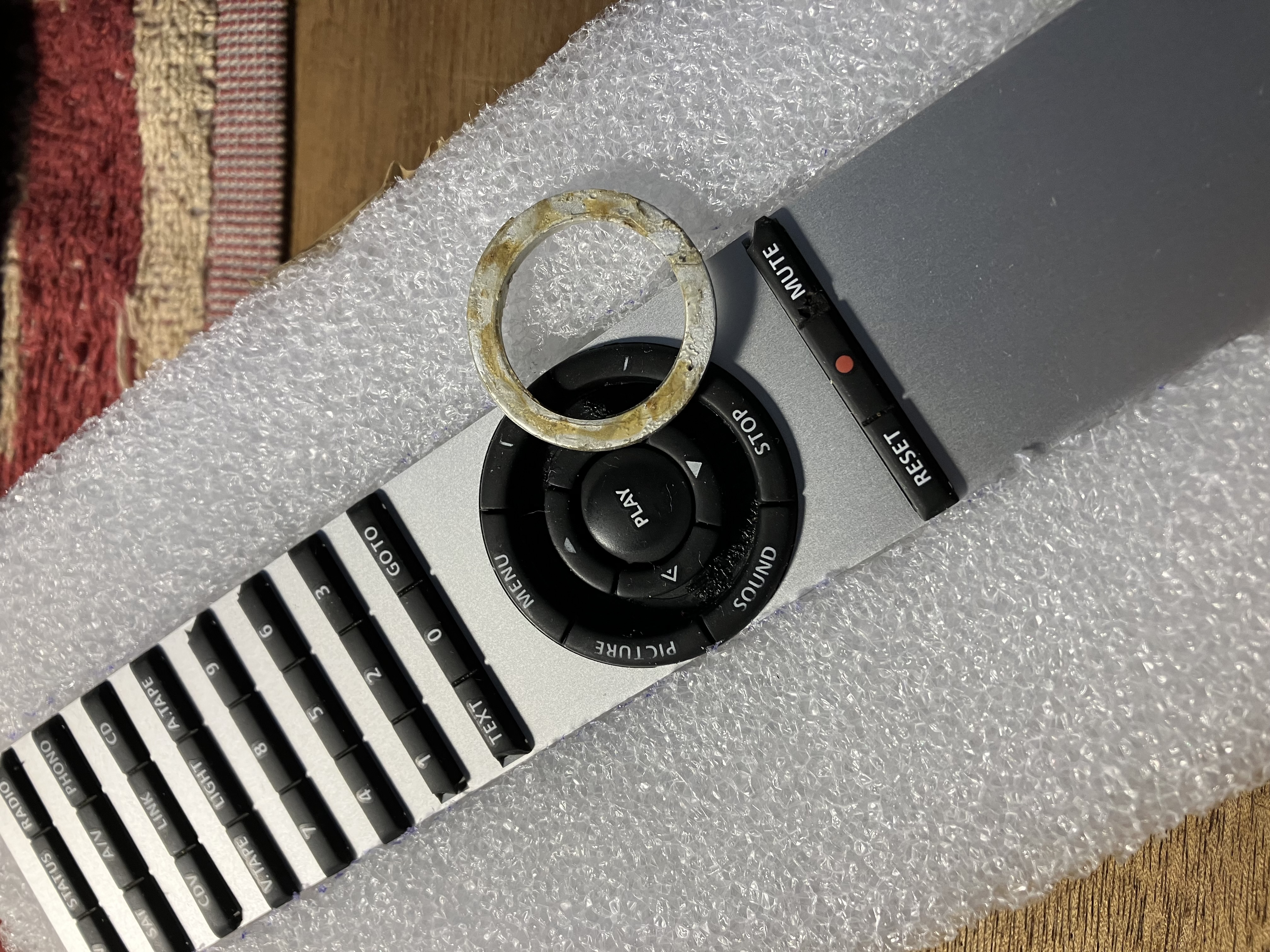
An extra question that has come up. the best set of keypads is missing the round aluminium ring, but I have that available on another set of keypads. How can this aluminium ring be removed. Is it glued down or only held in by the rubber keys?
Attachments:
You must be logged in to view attached files.Location: Denmark
29 December 2025 at 12:58 #72168I am not sure why you can’t upload photos normally – I’ll send a message to Multicare.
I just dug out an old BL5000 keyboard (actually one that Beoworld member Leslie sent me many years ago) and prised out the metal circle with a guitar plectrum. It came out quite easily, but looks like it was originally glued in place:
Location: Warwickshire, UK
My B&O Icons:
29 December 2025 at 15:24 #72171MadskpGOLD MemberI just dug out an old BL5000 keyboard (actually one that Beoworld member Leslie sent me many years ago) and prised out the metal circle with a guitar plectrum. It came out quite easily, but looks like it was originally glued in place:
Thank you very much for testing 🙂 Will try to do that when I start washing the keypads.
Location: Denmark
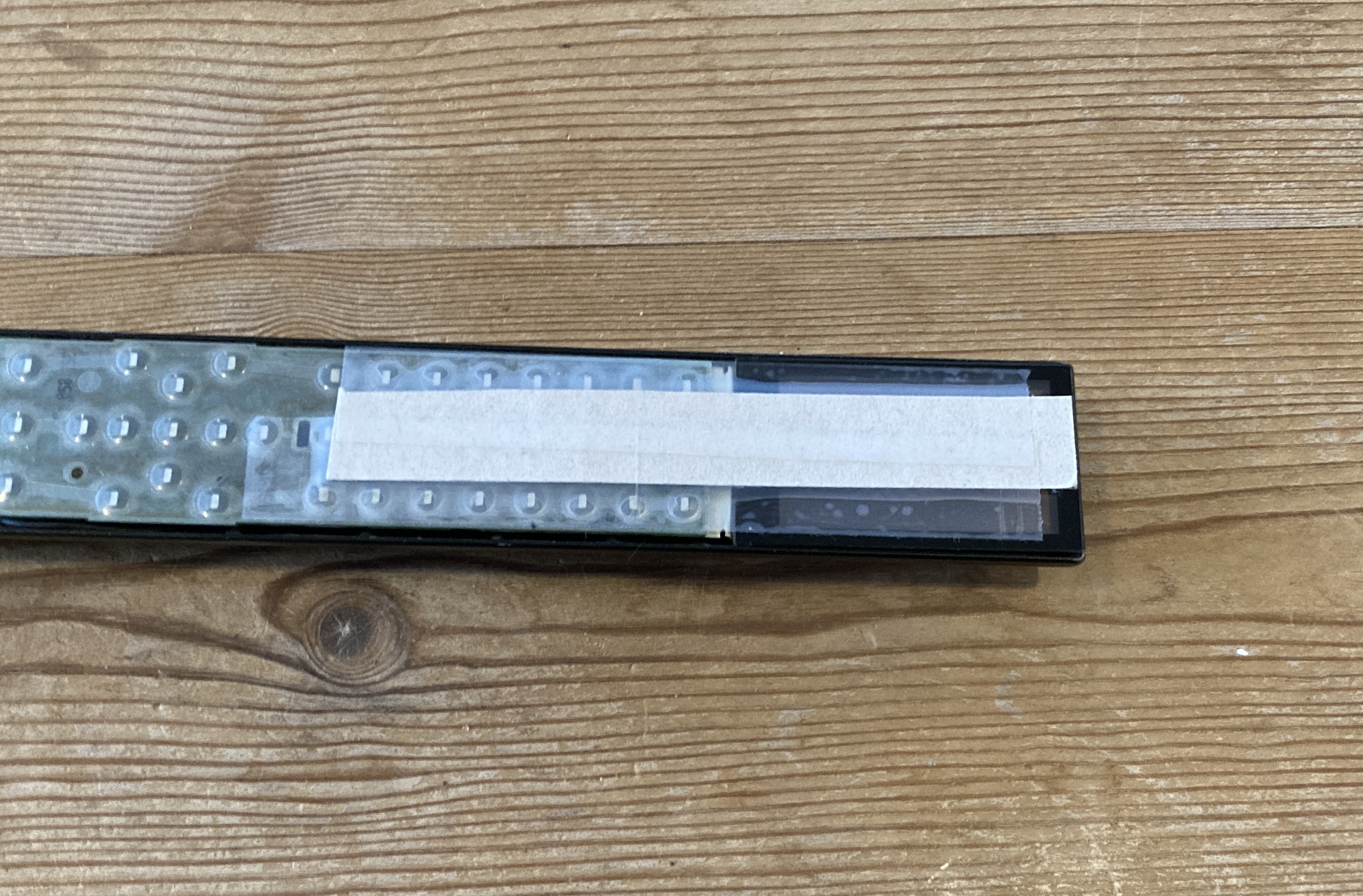
29 December 2025 at 16:23 #72172I normally use this 3M300LSE double sided tape to reattach the aluminium ring back to the keypad.
At the attached picture how its used.If the aluminium ring isn’t lose I’ii leave it on the keypad when cleaning in warter with dishwash soap.
/steffen
Attachments:
You must be logged in to view attached files.My B&O Icons:
29 December 2025 at 17:27 #72175MadskpGOLD MemberI normally use this 3M300LSE double sided tape to reattach the aluminium ring back to the keypad.
At the attached picture how its used.If the aluminium ring isn’t lose I’ii leave it on the keypad when cleaning in warter with dishwash soap.
/steffen
Thanks Steffen. I have just taken out one aluminum ring because it had a big scratch and the keypad it is sitting in has cracks. This ring did not seem to have any glue, but the back had the same surface as the top, so it can be used as a replacement after all.
Location: Denmark
17 January 2026 at 17:53 #72647MadskpGOLD MemberIt has been a little busy since christmas, but I had some time to proceed on the Beolink 5000 project this weekend.
I had some thought about how to protect the display cable on the Beolink 5000 with no missing lines, and ended up with a relativly simple solution. I placed a piece of thick cardboard on the front of the remote covering the display and about the same lenght on the keyboard part. Then I used regular tape to attache the cardboard to the surface of both the display and the keyboard section. On the keyboard PCB i put a piece of tape around it all to secure it.
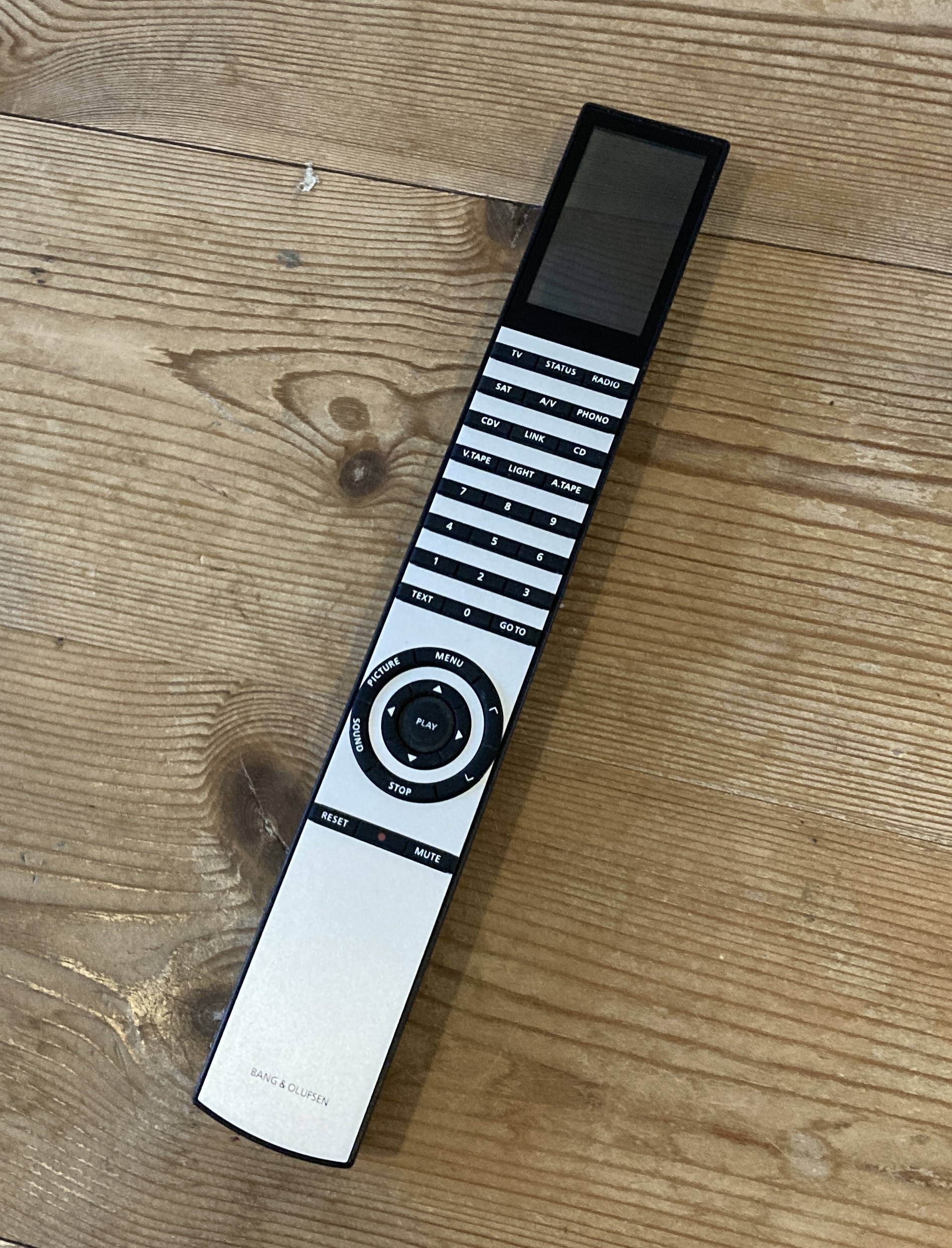
This was very helpfull when I removed the PCB and display from the housing, and when I removed the remains of double sided tape from the edges on the back of the display.However I had to remove it when I remounted the parts as there is need for some flexing in the lenght direction when putting in the PCB after the display has been secured in place with new double sided tape.I did not get to take anymore pictures in the process, as some of it was very fiddly to work on.But to sum up I cleaned all the mechanical parts like rubber keys, aluminum top and housing. Also I gave the housing af fresh layer of black spray paint to cover some of the dents it had on it.After that I remounted the IR PCB with the best of the battery cases, and connected the Keyboard PCB. This parts was very tricky when the IR PCB is already mounted. Maybe a better way would be to connect the PCB’s and then mount it all in one operation?Anyway, after putting it all back together I am pleased to announce that I now have a Beolink 5000 with working 2way functionality and no missing lines in the display
Location: Denmark
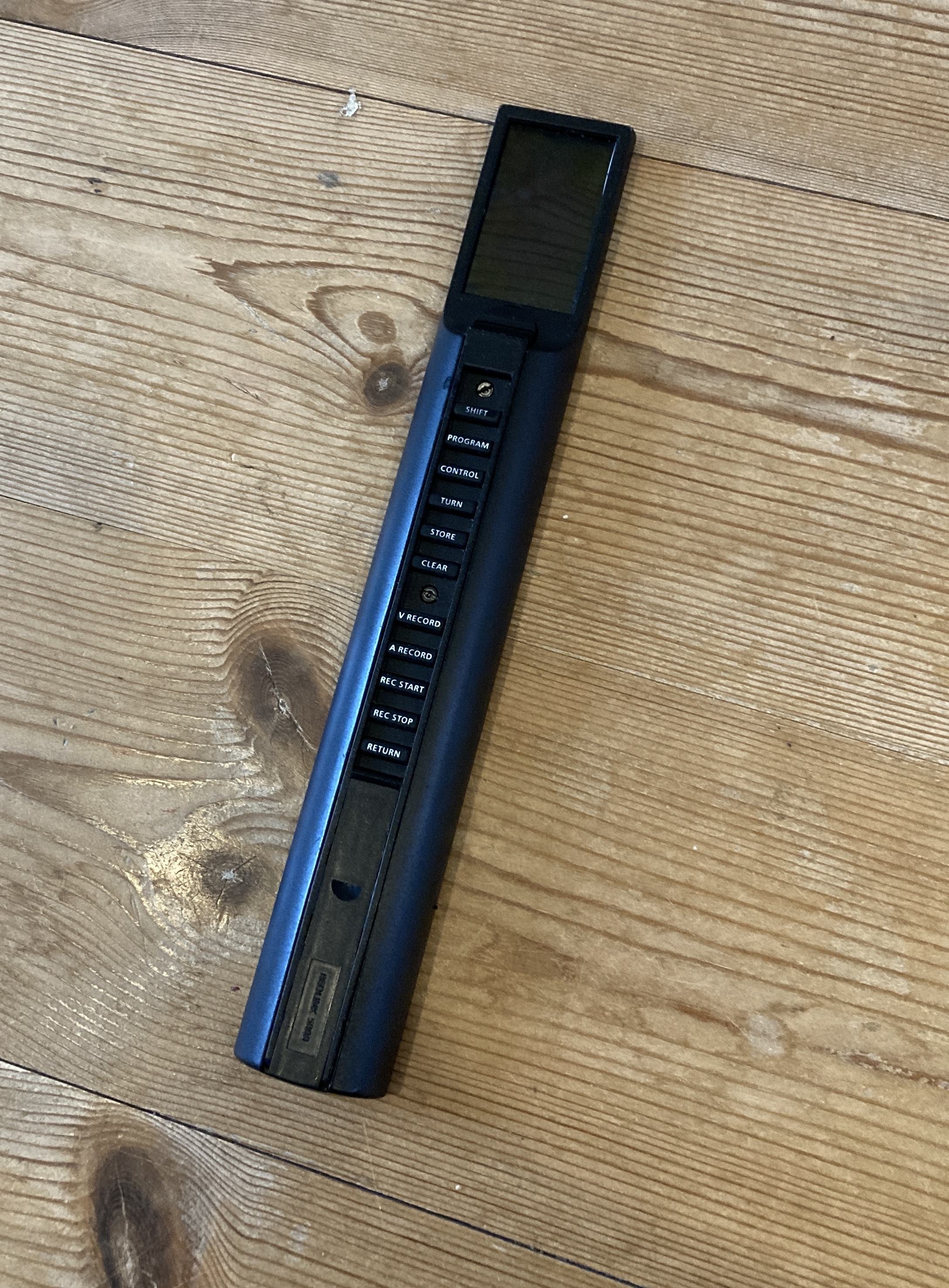
17 January 2026 at 17:59 #72651MadskpGOLD MemberAnd a few full body shots front and back
The other Beolink 5000 is not going to work for now as both the battery case and some of the internal plastic structure in the housing is damaged. Also it has missing lines and very visible artifacts, so that will require some more serious restoration and a couple of spare parts.For now I will try to play around with the working Beolink 5000, and I will of course have to buy the wall mount for it 🙂BTW one of the reasons I did get a Beolink 5000 was to confirm wheether my Beolink 7000 2way reapir was not working or if it was my 2 way systems that had faults. It seems to be the Beolink 7000, so I will have to get back working on that at some pointLocation: Denmark
17 January 2026 at 20:16 #72661MadskpGOLD MemberOh and BTW thanks to all for the valuable input on restoring this 🙂 Very appreciated
Location: Denmark
-
AuthorPosts


- You must be logged in to reply to this topic.