Generic selectors
Exact matches only
Search in title
Search in content
Post Type Selectors

Home Forums Product Discussion & Questions BeoLab SOLVED !! beolab penta MK2 display questions

Viewing 6 posts - 1 through 6 (of 6 total)
  • Author
    Posts
  • #67392
    nitro2
    BRONZE Member

    Hi forum ,


    Can someone shine a light on these 2 questions;

    1 = how to revive the backlight on these mk2 units , the are very dim ,

    i was looking for an ldr in the schematic but apparently went blind ( aka could not find it )

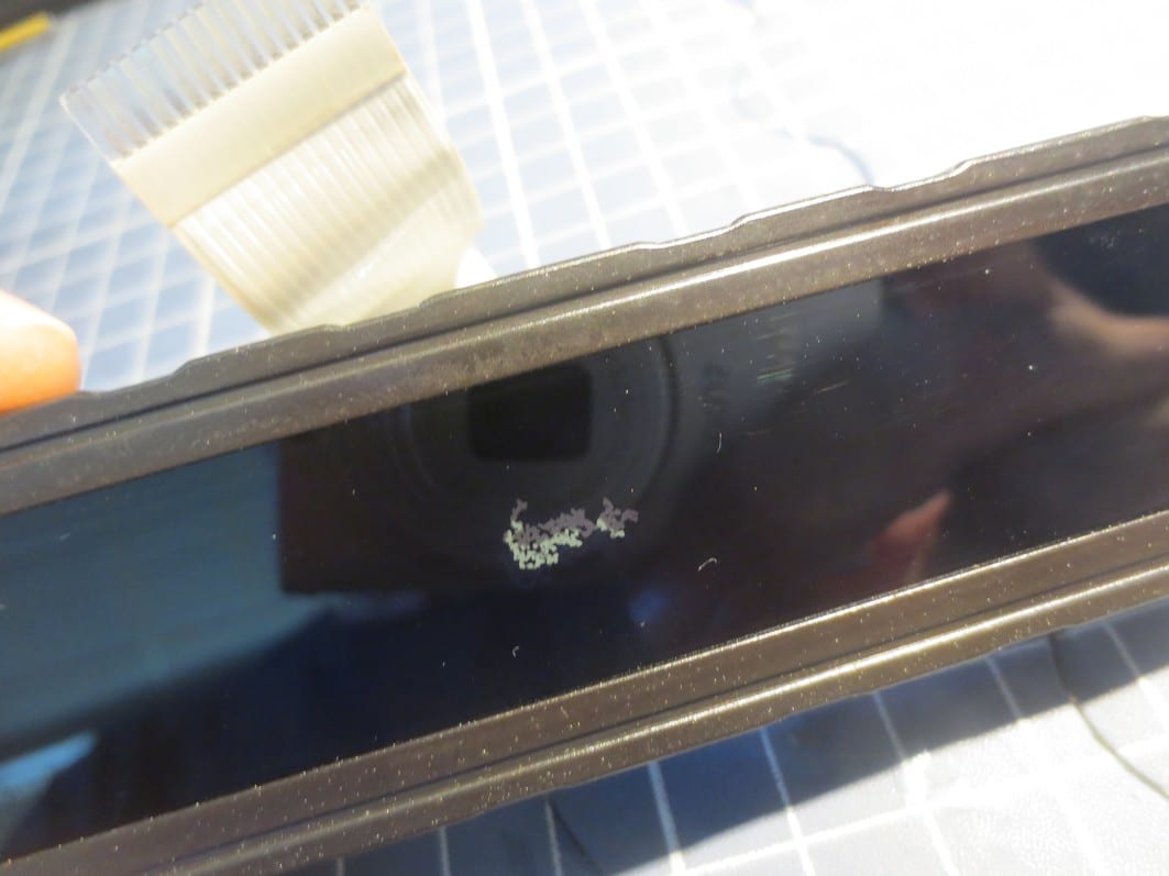
    2  = does someone have a orange lcd ??  mine  has a lcd-gap ( lcd matrix damaged ).

    • This topic was modified 1 month ago by nitro2.
    • This topic was modified 2 weeks ago by nitro2.
    Attachments:
    You must be logged in to view attached files.
    #67962
    nitro2
    BRONZE Member

    question 2 has been resolved , found someone who could supply me with a new lcd.


    Question 1 remains open , is there a way to give the backlight more intensity ?

    #68607
    nitro2
    BRONZE Member


    • This reply was modified 2 weeks ago by nitro2.
    #68995
    Homersaurus
    BRONZE Member

    With regard to the intensity, there is a preset trimmer that adjusts the “angle of viewing” so it changes the intensity not by directly increasing or decreasing the brightness but by altering the LCD with respect to the viewpoint.

    There is an LDR (light dependent resistor) which can alter the brightness which points downwards into the Penta – not outwards through the display cover and is not visible.  Ambient light is filtered through the speaker cloth and affects the LDR by shining through the cloth onto the LDR. Test it by shining a pencil sized torch onto  the speaker cloth just below the right hand side of the the display cover.

    The attached photo, from a MkII Penta shows the LDR and the trimmer on the boards.


    Attachments:
    You must be logged in to view attached files.
    #68997
    Homersaurus
    BRONZE Member

    That’s the LDR on the right by the multi-coloured connector wire.

    Attachments:
    You must be logged in to view attached files.
    #68999
    Homersaurus
    BRONZE Member

    The LDR is on the schematic for the board; 23 and 24 cover the two boards in the display.

Viewing 6 posts - 1 through 6 (of 6 total)
  • You must be logged in to reply to this topic.