


Home › Forums › Product Discussion & Questions › BeoLab › BeoLab 8000: 5-pin cable from RCA-PCB to LED-PCB sensitive
- This topic has 24 replies, 6 voices, and was last updated 2 years, 6 months ago by
 dantest.
-
AuthorPosts
-
1 January 2023 at 05:20 #39864
 BRONZE Member
Keith Saunders posted about a modification needed to Beosound 6000 with this issue. I will D/M him and ask if he has any input. https://archivedforum.beoworld.org/forums/p/3280/24478.aspx Power-link mode: Mount a 1 nF capacitor across 03D1. Line mode: Mount a diode 1N4148 between 03R126 and 03D19. Apparently, B&O designed a fix?
Luke,
I received your PM and I can confirm that the answer I gave in the thread in the archived forum is correct.Both the Beolab 6000 and Beolab 8000 had a similar reported problem, BUT they were not completely the same, but similar and B&O’s official solution were very different.
For the Beolab 8000 a formal notice was sent out to all B&O dealers on 1st March 2002 which had the following information.
Does not switch off after standby from Master
Symptom:Switches on and off by itself, or does not switch off after standby from Master.
Cause:
Self-triggering when using the line-input socket.
Solution:
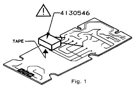
Mount a capacitor 0.33 uF/250V across the primary terminals of the mains transformer.
Please note that the capacitor must be the safety type supplied under part no. 4130546.
Remark: The modification is only to be used in sets with serial no. lower than approx. 09459585. From this serial no. the layout of PCB 02 has been modified to prevent the problem. (PCB 02 version F).
Regards
Keith..
Location: Hampshire, England
2 January 2023 at 18:06 #39865@Luke
Thanks for your extensive response.
I have now also read the thread about the BeoLab 6000 with power on off issue. And the comment by Steve Saunders and his modification suggestion:
- Power-link mode: Mount a 1 nF capacitor across 03D1.
- Line mode: Mount a diode 1N4148 between 03R126 and 03D19.
But I think that further on in this thread, he mentions that this modification only goes for the BeoLab 6000 with serial number up to 10500000. Which is quite old.
Concerning my own BeoLab 8000 with which I started this thread … It is currently dead, not responding at all to power. No red light, no relay clicking. So I am a few steps back, to get it back alive again first.
Concerning your PDF of the circuit and marked suspect problem components, hard for me to judge. But I am very interested to hear what others like Steve think about this.
Hope this thread continuous!
Location: The Netherlands
Favourite Product: BeoSound 9000
My B&O Icons:
 2 January 2023 at 19:45 #39866
Thanks Keith,
So my beolab 8000 speakers being serial number 19… / 2007 model year seems that design fix has already been applied for this issue.In regards to KolfMAKER he found that exchanging transformer board did fix his issue so maybe this ties in with his issue and he can apply this solution depending on the serial numbers of his speakers. He hasn’t mentioned serial numbers from what I have read.
Fix applied to boards – PCB 02 version F onwards.I confirm board number on my speakers and test on suspect components on my boards and see if replacing them can resolve the sensitivity issues I am seeing.
Many Thanks,
Luke
3 January 2023 at 13:04 #39867@ Luke & all
Thanks for hopping into the other thread (this one)
If I now look back to my issues described in this thread, I start thinking that a lot has probably been caused by a dying T2 Trafo. As described earlier in this thread, I already noticed an inconsistent voltage on the T2 output side:
- 20 volt on pin 7 & 9
- 23 volt on pin 10 & 12
And a few days later it now looks like this:
- 0 volt on pin 7 & 9
- 0 volt on pin 10 & 12
So I suspect that T2 is or is big part of my issues. I will now first place a new T2 trafo, measure and test again. And then come back to the forum with an update.
Location: The Netherlands
Favourite Product: BeoSound 9000
My B&O Icons:
7 January 2024 at 04:38 #39868dantestBRONZE MemberHi, I am having the exact same problem (he Auto stand-by does switch to OFF, but after one second immediately switches ON again, and then repeatedly goes ON – OFF – ON – OFF.) . I am now disassembling the unit and removing all the rot foam. how did you solve the issue and what should I look at (disclaimer, I have no soldering skills is this something I can do myself?
-
AuthorPosts


- You must be logged in to reply to this topic.