


Home › Forums › Product Discussion & Questions › BeoGram › BeoGram 1000: alternative RIAA PreAmp ?
- This topic has 32 replies, 8 voices, and was last updated 3 years, 6 months ago by

-
AuthorPosts
-
19 August 2022 at 09:17 #36569
 DillenModerator
Different transistors and diodes were used in production.
Indeed OA81 are found in some versions.Mexking, I still have your RIAA here, remember.
– And it actually has OA81 fitted.Martin
19 August 2022 at 11:01 #36570Component search
I have done a quick check for components. There’s two challenges that I see:
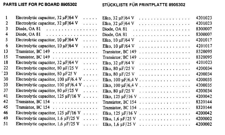
- Some components have values that are not very common any more, e.g.: capacitor 10uF/6.4v, 80uF/25v, 100uF/6.4v, etc.
- I have to make sure that the sizes of the components chosen are the same, to make it fit on the original board remake.
Questions(a) Can anyone recommend an online source where components with these ‘vintage’ values can be found?
(b) Are the diode types AO70 & AO81 interchangeable? Or does it depend on the version of the board which one to choose?Location: The Netherlands
Favourite Product: BeoSound 9000
My B&O Icons:
 19 August 2022 at 17:08 #36571
here

Location: Mexico city
19 August 2022 at 17:49 #36572Try Mouser Electronics, but you will have to go for radial leaded caps in some cases, looking at the PCB you should be able to fit them. start looking for 80/25 if not there, look for 82/25 and so on just keep it inside the 20%. If you dont find it check with Martin, I know he has some of them if not all. I will go check in my stock I have 80 and 100 axial in stock but dont remember which V
Location: Mexico city
19 August 2022 at 17:56 #36573Component list

Location: Mexico city
20 August 2022 at 11:46 #36574RaMaBoGOLD MemberHi,
the components that make headache are not so critical:
80µF / 25 V could be replaced with 100µF /25 V
33µF / 64V could be replaced with 47µF / 63V
1,6µF /25V could be replaced with 2,2µF / 25V or to be as near with a 4,7µ / 25V in series with a 2,2µF /25 V resulting in 1,5 µF /25V but not really necessary.
125µF / 16V could be replaced with 100µF /16 V or to be as close as possible get a 100µF /16V with a parallel 22µF /16V
The 80µF and 33µF are used to ‘clean’ the supply and bias voltages.
The 1,6 µF is for removing the DC offset from the input and output so i would use just a simple 2,2µF. It has no influence to the frequency response of the RIAA preamp.
Also every capacitor for 64V could be replaced with a 63V typeI hope this helps 🙂
Location: Near Munich
My B&O Icons:
20 August 2022 at 14:34 #36575Thnx @Mexking & @ RaMaBo !
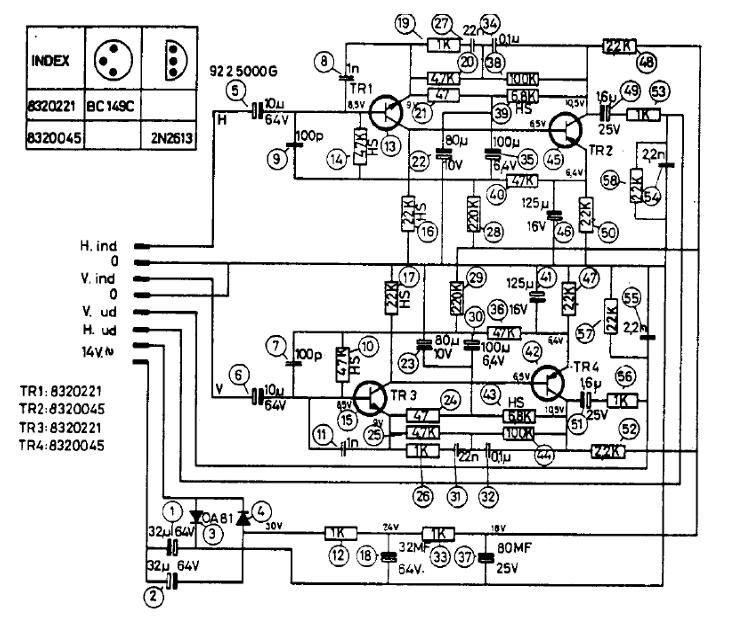
Interesting that there are some differences in the values of certain components; between the info I posted in the start of this Thread and the info in the schematics & parts list of Mexking.
E.g.
- Capacitor #22 and 23 = 200uF/25v vs. 80uF/25v
- Capacitor #49 and 51 = 80uF/25v vs 1.6uF/25v
Is this correct?
Location: The Netherlands
Favourite Product: BeoSound 9000
My B&O Icons:
20 August 2022 at 17:46 #36576There are apparently at least 2 different versions, one with OA81 and one with OA70 fitted. The OA81 has the smaller caps and different transistors fitted, yours and my pic of the PCB are identical, whereas your trace with components pic is different. So you will have to decide which one you want to copy.
@ Martin, I remember the RIAA, the BG 1000 is still going strong playing with my son in CPH together with the BM 1900 you also restored connected now to some Sonos equipment, but let the young ones play around. I would here put a big smiley if I could
Location: Mexico city
22 August 2022 at 11:21 #36577I think you guys are right, about the two versions.
I also think the 2nd version is ‘easier’ to rebuild as the values of the capacitors are closer to components available.
Location: The Netherlands
Favourite Product: BeoSound 9000
My B&O Icons:
22 August 2022 at 13:18 #36578DillenModeratorThere are several, slightly different, versions.
Three of the ones shown here have different transistors, and the last one is an entirely different (earlier) version, mainly seen in 41FV and 42FV.Martin
23 September 2022 at 10:52 #36579In the process of re-building the original BeoGram 1000 Pre-Amp PCB …
I am now selecting the capacitors for my order. I noticed that it is hard to find the exact same values as the originals. For the voltage it is not such a problem, I can just step up the value for the voltage, and it will still work.
For the capacitance I am not sure. For instance, a capacitor with 32uF is hard to find. Though I do find 33uF. Also 1.6uF cannot be found, but 1.5uF is available.
Also 80uF, I cannot find.
Question
- Will choosing 1.5uF instead of 1.6uF work?
- Same; will choosing 33uF instead of 32uF work?
- Same; will choosing 100uF instead of 80uF work?
- Same; will choosing 150uF work instead of 125uF?
PS. I have searched via:
- https://www.nichiconcapacitors.com/shop/
- https://nl.rs-online.com/web/c/passive-components/capacitors/aluminium-capacitors/
- https://nl.farnell.com/c/passive-components/capacitors/aluminium-electrolytic-capacitors/leaded-aluminium-electrolytic-capacitors
Location: The Netherlands
Favourite Product: BeoSound 9000
My B&O Icons:
23 September 2022 at 16:20 #36580Hi,
Yes to all! Except for 5 ☺️
Even 2.2 µF will do.
23 September 2022 at 16:30 #36581Very interesting to see this overview of 4 different versions Martin!
Also interesting that the top left and right and the bottom left, are different but have the same number on the top of the PCB and the same number on the label at the bottom.
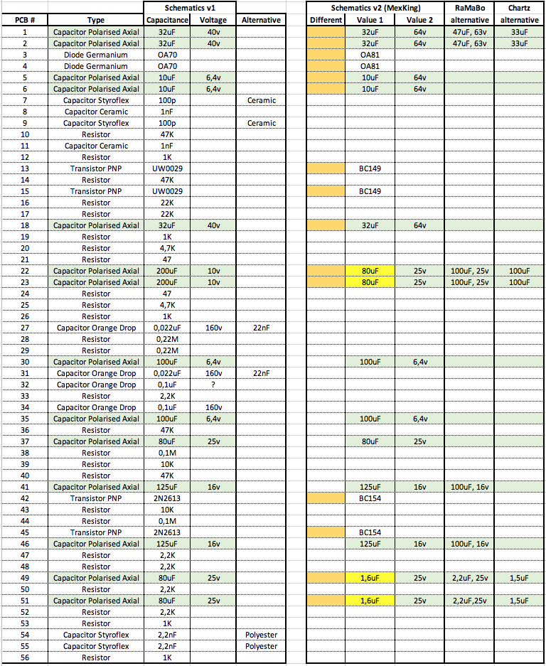
So I have now component list for two versions, see the attached. The right one is based on the info mentioned by Mexking earlier in this thread. And added the alternatives for certain capacitors mentioned by RaMaBo and Chartz.
I think MexKing mentioned the left component list belongs to the PCB trace pattern also shown in this thread.
Question
- Are there really differences in the trace patterns between these two versions?

Location: The Netherlands
Favourite Product: BeoSound 9000
My B&O Icons:
-
AuthorPosts


- You must be logged in to reply to this topic.