Home › Forums › Product Discussion & Questions › BeoLab › A question on circuit board from my beolab 6000
- This topic has 3 replies, 3 voices, and was last updated 3 years, 6 months ago by

-
AuthorPosts
-
4 August 2022 at 03:30 #36638
mojofml
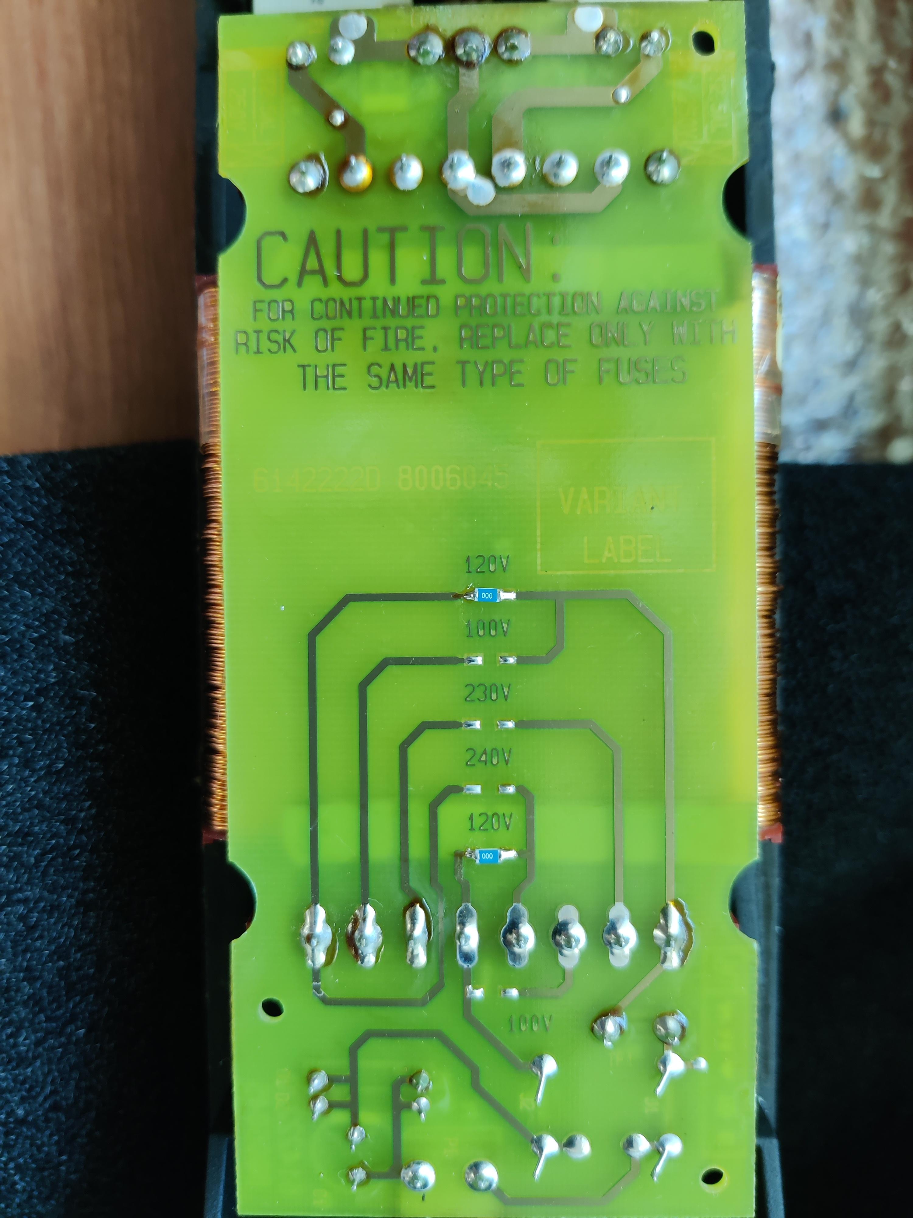
BRONZE Member4 August 2022 at 15:54 #36639You’d have to remove both the bridges (i.e below each 120V label) and replace across the 240V.
If you consider that the transformer winding terminals are numbered 1 to 8 from the left, then for a 240V supply you need 1 to be connected to 5 (hence the bridge), with the input supply connected to 4 and 8.
(That’s from the service manual – avail to Silver and Gold Members!)
Location: Warwickshire, UK
My B&O Icons:
5 August 2022 at 12:20 #36640mojofml
BRONZE MemberYou’d have to remove both the bridges (i.e below each 120V label) and replace across the 240V. If you consider that the transformer winding terminals are numbered 1 to 8 from the left, then for a 240V supply you need 1 to be connected to 5 (hence the bridge), with the input supply connected to 4 and 8. (That’s from the service manual – avail to Silver and Gold Members!)
Thanks for your advice and the silver/gold material!
Is it really just as simple as that to change the voltage input?
Thanks!
5 August 2022 at 12:45 #36641 BRONZE Member
Is it really just as simple as that to change the voltage input?
Yes it is..
Most older B&O products use transformers with at least two primary windings. When these windings are placed in parellel then it uses 110 volts and when in series its 220 volts..
In this case they have gone beyond or extended the two primary windings to allow voltages of 100 & 120 volts with 230 & 240 volts.
Location: Hampshire, England
-
AuthorPosts
- You must be logged in to reply to this topic.


