Home › Forums › Product Discussion & Questions › BeoLab › BeoLab 8000: 5-pin cable from RCA-PCB to LED-PCB sensitive
- This topic has 24 replies, 6 voices, and was last updated 2 years, 1 month ago by
dantest.
-
AuthorPosts
-
15 October 2022 at 01:38 #39844
 BRONZE Member
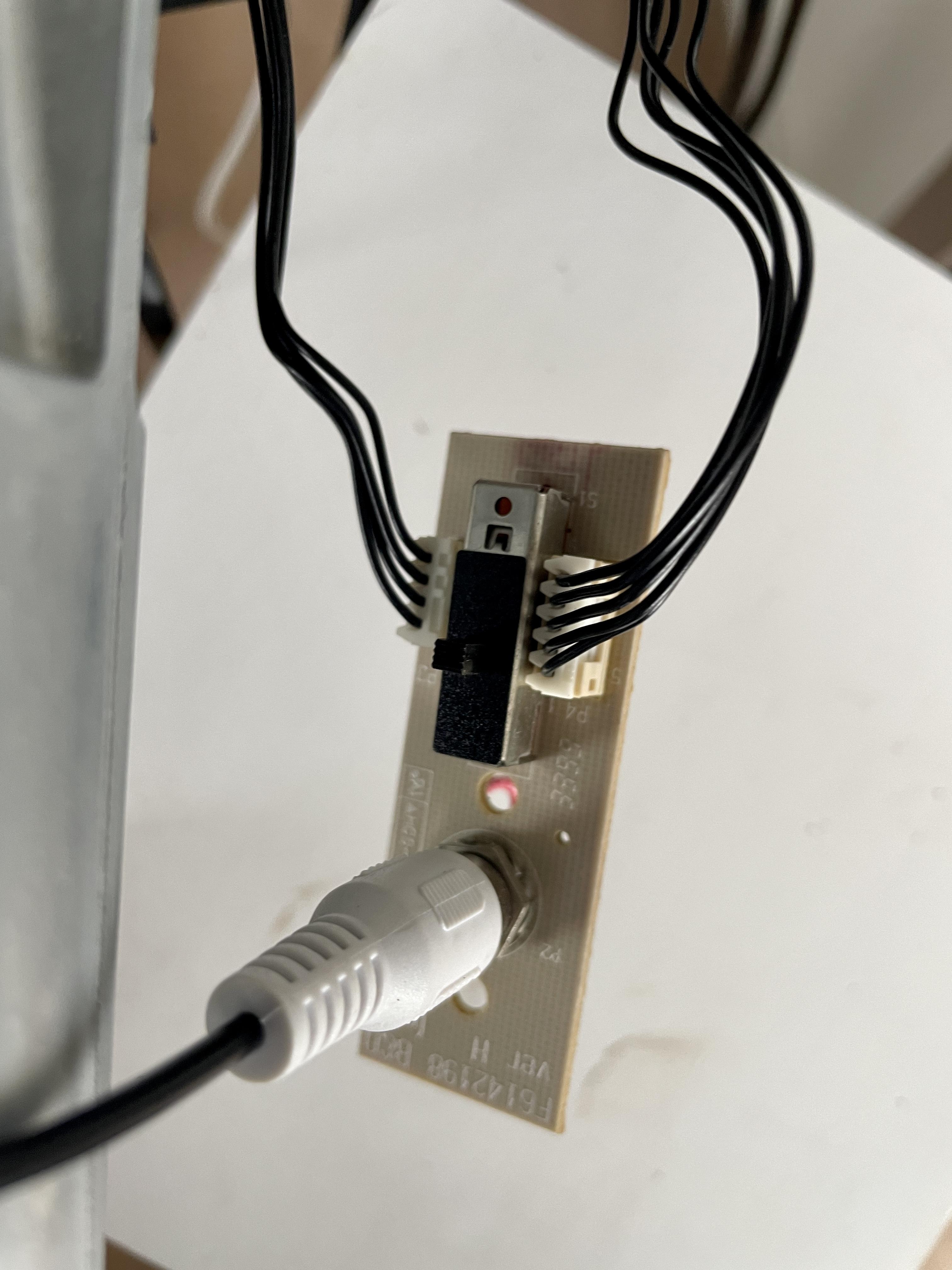
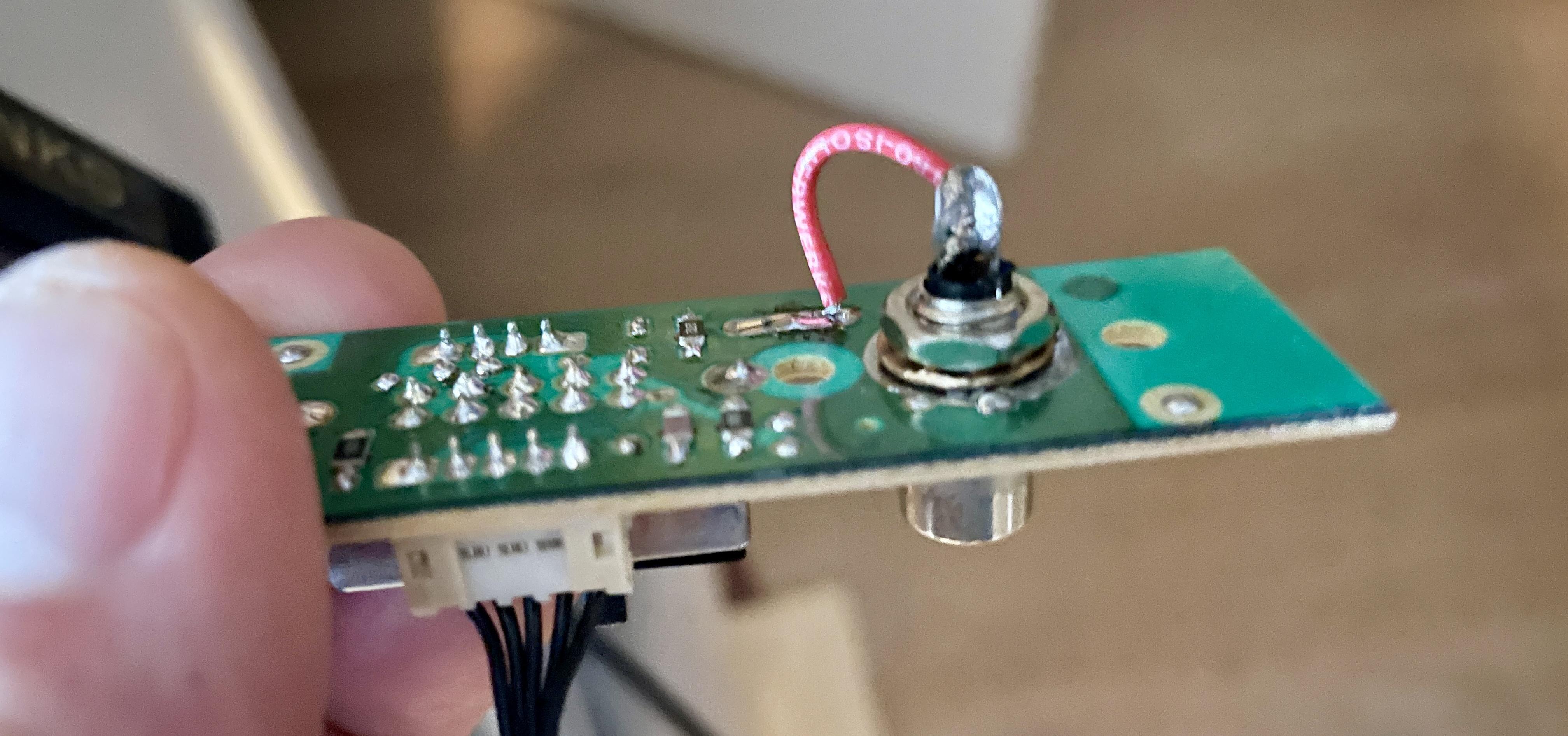
One of my BeoLab 8000’s has an issue with some noise & hum. After several checks, I thought to have found a possible issue with the 5-pin cable from the RCA on PCB 05 to the LED board/PCB 06 (the right wire in the picture).
Some checks I made:
- When I touch the cable, the hum increases.
- When I touch the other cable (4-pin, on the left in the picture), nothing happens.
- When I replaced the 5-pin cable with another but new, it still responded when touched (same as the original 5-pin cable)
- When I connect my iPhone to the RCA connector on this PCB, the noise & hum are almost gone. But when touching the 5-pin cable, the BeoLab switches from stand-by to ON.
Question
What can this be? Where can I look for?Location: The Netherlands
Favourite Product: BeoSound 9000
My B&O Icons:
16 October 2022 at 17:14 #39845Die_Bogener
BRONZE MemberCheck this board and the LED board for broken solder pins/pads. Especially the ground pins… and use a magnifying glass… BL8000 have lots of problems with broken pads. More or less ALL active loudspeaker have this problem. Sound is stress to solder pads, it’s mechanical stress and it is just a matter of time and played volume…
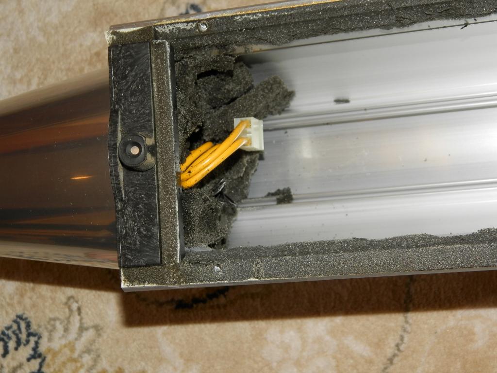
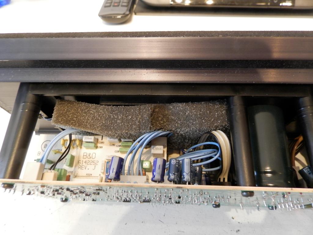
… and for the acid foam. Maybe broken lines in the preamp section…
16 October 2022 at 17:30 #39846Die_Bogener
BRONZE Member16 October 2022 at 17:43 #39847 BRONZE Member
Thanks! I will make those checks and come with my findings.
Location: The Netherlands
Favourite Product: BeoSound 9000
My B&O Icons:
22 October 2022 at 16:21 #39848 BRONZE Member
Findings
First I disconnected and took PCB05 and PCB06 out of the speaker. Checked again for foam rot rests. Did some extra cleaning to be sure. Then I made following checks and did resoldering.
Checks
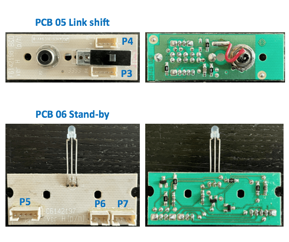
PCB 05 – Link shift (in outside foot)- Continuity: measured continuity on all traces and solder points connected > OK.
- Re-soldering: re-soldered all solder points, incl. connectors and component pins > Done.
PCB 06 – Stand-by (in bottom speaker casing)
- Continuity: measured continuity on all traces and solder points connected > OK
- Re-soldering: re-soldered all solder points, incl. connectors and component pins > Done.
P4 Connector (between PCB05 & PCB06)
- Continuity: measured continuity on all 5 pins of the cable > OK.
Next
After this I put the BeoLab back in original configuration: PCB06 screwed back in normal position, PCB05 connected but hanging loose. iPhone connected (as audio source) via external mini-jack to RCA cable, connected to RCA in foot. Result: There is a little hum, but Auto stand-by does switch OFF.
Findings:
- When the P3 connector or cable is touched, Auto stand-by switches ON. But when let loose, it also quickly switches OFF.
- When the P4 cable is touched, nothing happens.
- When the P6 connector (audio cable) on PCB05 (Link shift) is touched, Auto stand-by also switches to ON. But also, quickly switches OFF when let go. This also happens when the connector of this same cable on the amplifier side is being touched.
Question
There still is sensitivity in the audio signal path.
What is the best next step I could make?Location: The Netherlands
Favourite Product: BeoSound 9000
My B&O Icons:
22 October 2022 at 17:07 #39849I’ve had similar hum issues on BL 8000s when using the RCA jack, but not when using PL. In my case the RCA jack began to loosen on the PCB board. At first the movement is barely perceptible, and the hum is soft. Over time as you move the speaker or touch the RCA cable, the jack wiggles more and the hum becomes an uncomfortable yowl. A mechanical issue surely caused by endless plugging/unplugging RCA over 30 years.
I re-soldered the feet of the RCA jack to back to the board, and (fingers crossed) all is well.
My B&O Icons:
23 October 2022 at 06:42 #39850 BRONZE Member
Thnx BeoTool!
In my case the RCA connector is not soldered to the PCB. It is fixed to the board by a nut, and I have tightened the nut well. So it must be another cause.
Any idea?
Location: The Netherlands
Favourite Product: BeoSound 9000
My B&O Icons:
23 October 2022 at 18:29 #39851Die_Bogener
BRONZE MemberSolder it.
Hum is just some millivolt.
Copper, mixed with chromeplated steel and nickel will always make some chemical noise.
You can also make a special shortcut plug for testing. Just a shorted Cinch connector.
Then you can test wether there is still humming…
25 October 2022 at 15:55 #39852 BRONZE Member
@Die_Bogener: As you suggedted, I connected a shorted RCA plug to the RCA connector on PCB05. Result: the hum is gone, Auto stand-by switches to OFF and stays OFF, and when touching the P4 cable, Auto stand-by does not switch on.
So this does look good! But now I need to make a next step, because I need the RCA connections, so I cannot keep them shorted.
Here’s some additional things I changed, tested and the results.
Checks 2
I took another look at PCB05: used a dentist tool to scratch along the edges of the RCA GND contact on the PCB, and at some other connections/traces on the PCB. Just to be sure, there’s no traces that make unwanted contact.
Tested after checks 2
- Input switch set to RCA: When the BeoLab was switched on again, the hum was more or less gone. The Auto stand-by does switch to OFF, but after one second immediately switches ON again, and then repeatedly goes ON – OFF – ON – OFF.
- Input switch set to PL: Auto stand-by switches OFF, and stays OFF > OK. Touching the PCB, P3 / 4 cables, etc. has no influence on Auto stand-by, it stays OFF > OK.
Checks 3
Extra checks on the GND and disturbances of the RCA plug on PCB05.
Tests with Checks 3
All checks done with the input selector set to RCA.
- Connected a wire between GND of the RCA connector outside shell above the PCB, and the GND underneath the PCB. Problem remains > No positive result.
- Put a metal cap over the RCA plug for shielding. Problem remains > No positive result.
- Connected my old iPhone with a ‘mini-jack-to-RCA’ cable to the RCA socket on PCB05 > No hum, Auto stand-by switches to OFF and stays OFF.
- In situation 3. I also touched the cable of P4 on PCB05. When touching it, Auto stand-by switches to ON. When releasing the P4 cable, Auto stand-by switches OFF again and remains OFF.
What bothers me is, that the Auto stand-by actually works well, but …
Touching the P4 cable makes the Auto stand-by switch ON again. Therefor, it is not yet working reliably.
Questions
- What do you conclude from this?
- What next step do you suggest?
Location: The Netherlands
Favourite Product: BeoSound 9000
My B&O Icons:
4 November 2022 at 13:02 #39853 BRONZE Member
Here’s another update. I made several other checks.
(Check 1) PCB 05 exchanged – I took the ‘PCB 05 Link shift board’ from another BeoLab 8000 and put it in the ‘trouble BeoLab 8000’.
(1) Result – Nothing changed. So, when nothing is connected to the RCA input on PCB 05: still a loud Hum. When an iPhone is connected to the RCA input, the hum is gone, Auto stand-by goes to OFF, but it also goes back ON again when I touch the 5-pin cable P4 on PCB 05.
So I conclude that the problem is not in PCB 05.
Observation: I noticed that when I touched the 3-pin JST cable from PCB 06 to the Amp, the Auto stand-by also switches to on. Same as when touching the 5-pin cable on P4 of PCB 05.
(Check 2) 3-pin JST cable changed – I hand-made another 3-pin JST cable to check if the original cable is the issue. This is to check if there is something wrong with the original cable between PCB 06 and the Amp.
(2) Result – When powering on, a slight hum/noise can be heard. Though it seems to be a higher pitch than before. Unfortunately, this hum/noise seems a bit to strong as the Auto stand-by does not switch OFF.
Observation: In the situation with the hand-made 3-pin JST cable, I noticed that when touching this cable or the 5-pin cable on P4 of PCB 05, nothing happens. Though, the BeoLab does not switch OFF.
Location: The Netherlands
Favourite Product: BeoSound 9000
My B&O Icons:
9 November 2022 at 11:20 #39854Die_Bogener
BRONZE MemberYour phone is isolated to Ground and to the 240V power.
RCA from somewhat else as a sound source is not isolated, it can have voltage to Ground. Sometimes very high voltages… i found already antennas with 190V (!!!)
Measure before plugging in the RCA the voltage between source and 8000. Measure ground to ground and signal to signal. There will be some voltage. Use DC and AC (!!!)
Use 1 (!!!) multi power plug/cord for source and 8000. Then the voltage should be gone.
If gone, your house installation has a problem.
10 November 2022 at 18:01 #39855 BRONZE Member
Thanks a lot Die_Bogener !
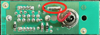
I now also noticed following. I touched the solder connection of the Left/Right signal wire (see red circle), with a screw driver. And immediately, the power switches ON. And when it is on, the hum/buzz gets stronger. Same happens (obviously) when I touch the back of the RCA connector (as it is the same connection of course). This does not happen when I touch the GND connection.
Concerning your advise to test by measuring (before plugging in the RCA):
- The voltage between source and 8000, both AC and DC
- Measure ground to ground
- And signal to signal
Just to be sure, do you mean …
- Ground & Signal at the RCA connector on PCB 05, at one side?
- And Ground & Signal at the P4 connector Amp PCB, as the other side?
Location: The Netherlands
Favourite Product: BeoSound 9000
My B&O Icons:
1 December 2022 at 10:07 #39856Die_Bogener
BRONZE MemberMeasure the sound source device to the beolab input. Without the RCA cabel connected.
Some houses use different power installations… and have problems with the 220V power distribution. Sometimes there are some hundred Volts between the power plugs.
Soooo, use ONE power plug for all of the hardware you use. Connect Beomaster, Beolab, all sources and loudspeaker with ONE power plug in the wall. And disconnect the antenna…
I had a BC9300 here with 190V Antenna to ground …making a spark when plugged in ! And when touched making a gribbling hand…
1 December 2022 at 10:14 #39857 BRONZE Member
Thnx Die_Bogener!
The issue of Auto stand-by clicking On-Off-On all the time, even happens when having no audio source connected to PL or RCA/Line in.
What about that ?
Location: The Netherlands
Favourite Product: BeoSound 9000
My B&O Icons:
6 December 2022 at 16:01 #39858 BRONZE Member
New checks & tests
I have just swapped the PCB01 TRAFO board from a working BeoLab 8000, into the troubling unit. I kept the other unit the same (PCB02 Power Supply & Amplifier board).
Result: no issues with Auto stand-by, just smoothly switching from ON to OFF/Stand-by when it should. Also no noise/buzz.
So something must be wrong on PCB01 the Trafo board.
Location: The Netherlands
Favourite Product: BeoSound 9000
My B&O Icons:
6 December 2022 at 16:28 #39859Die_Bogener
BRONZE MemberCheck the standby trafo. 2x 18V~
17 December 2022 at 12:04 #39860 BRONZE Member
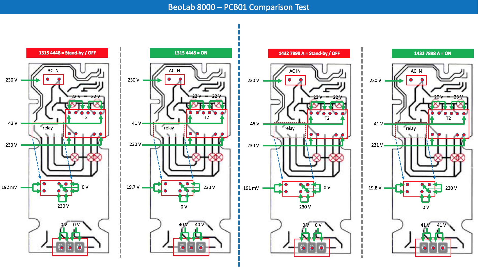
I have now been able to do some measurements on PCB 01. I did the same on another PCB 01 from a different well functioning BeoLab 8000, and put them side by side. It looks like this:
On the left side of the blue dotted line, the well functioning BeoLab 8000:
- Left/red = measurements in stand-by/Off mode.
- Right/green = measurements in On mode.
On the right side of the blue dotted line, the BeoLab 8000 with issues:
- Left/red = measurements in stand-by/Off mode.
- Right/green = measurements in On mode.
So compared, what I see:
- T2 shows 20 and 23 V, so not even.
- Else, I see no differences.
Question
Is there anything that we can conclude from this, that helps towards a solution?
Location: The Netherlands
Favourite Product: BeoSound 9000
My B&O Icons:
18 December 2022 at 10:13 #39861Die_Bogener
BRONZE MemberThe voltage/load of the 2x18V is not quite symmetric, the load is unsymmetric… around ~20V is ok.
The problem does not move with exchanging the power boards?
If no movement, the problem is not the power supply…
Probably the amplifier itself… broken line, defect cap… check the +/- 15V supply. The on/off logic is on the amplifier…
20 December 2022 at 12:22 #39862 BRONZE Member
Thanks @ Die_Bogener, for your recommendations.
What I did next:
I swapped the PCB01 TRAFO board from a working BeoLab 8000, into the troubling unit. I kept the other unit the same (PCB02 Power Supply & Amplifier board).Result:
- No issues with Auto stand-by, just smoothly switching from ON to OFF/Stand-by when it should.
- When the BeoLab with this (swapped) Trafo board is on, there is also no noise/buzz.
- When I touch the 5-pin cable when the BeoLab is ON, there is some noise/buzz.
- When I touch the 5-pin cable when the BeoLab is OFF, it does not cause the BeoLab to switch to ON.
Conclusion:
The amplifier seems to be fine. But the Trafo board/PCB 01 must be having the problem.
Question:
Since the voltage measurement (see earlier post) on the T2 trafo shows a non-symmetric load (20 Volt vs 23 Volt):
- Is the T2 trafo the problem source, or could it still be some other part or component on PCB01?
- If T2 has to be replaced, what is a good source to find a (reliable & affordable) replacement?
Location: The Netherlands
Favourite Product: BeoSound 9000
My B&O Icons:
30 December 2022 at 07:11 #39863Hello,
Thanks to KolfMAKER for the excellent posts. I am having similar issue on my Beolab 8000 MK2 SN 19.
My Problem:
speaker set to Line in / RCA. Only power lead connected.
Speaker powers on, green light then turns to standby momentarily then immediately back to power on, this just sequence keeps repeating.
No issues when connecting with Powerlink.
I have X2 speakers and when checking the other “good one” it just stayed in standby with only power line connected, however when messing with it some more. I got it match the same fault as the other bad speaker, with it jumping out of standby a few times, before it settled into standby mode.This seems to be a sensitivity issue related to the signal sensing circuit. It appears one of my speakers is too sensitive and the other is on the limit.
I have tied powering off all other electrical systems in the house / testing speakers in same location and I get same issue replicated on the one speaker.
From your previous post:
“Since the voltage measurement (see earlier post) on the T2 trafo shows a non-symmetric load (20 Volt vs 23 Volt):
· Is the T2 trafo the problem source, or could it still be some other part or component on PCB01?
· If T2 has to be replaced, what is a good source to find a (reliable & affordable) replacement?
This small inbalance in transformer output may be pushing you speaker over the sensitivity limit?, as earlier poster said this transformer output difference should be ok / within limits.
When reviewing previous posts on this issue
Keith Saunders posted about a modification needed to Beosound 6000 with this issue. I will D/M him and ask if he has any input.
https://archivedforum.beoworld.org/forums/p/3280/24478.aspx
Power-link mode: Mount a 1 nF capacitor across 03D1.
Line mode: Mount a diode 1N4148 between 03R126 and 03D19.Apparently, B&O designed a fix?
Also has any one got MK2 Beosund 8000 diagrams / updated service manual, im not sure if this on the site as im not a silver gold member any more.
In addition, I have reviewed the wiring for line input sensing circuit that seems to be causing the issue and possible problem components however I’m not too sure. Find attached
Best Regards,
Luke
-
AuthorPosts
- You must be logged in to reply to this topic.


