Forum Replies Created
-
AuthorPosts
-
 marchamBRONZE Member
Thanks, Glitch; I appreciate the feedback and help along the way!
While I’ve made mistakes throughout the process, and the board has certainly seen better days visually, I’ve taken the time to improve my soldering skills and learn how to better care for my equipment. Funny enough, I have quite a bit of repair gear sitting around now (even if I don’t know how to use it all 100%): a soldering station, variable power supply, multimeter, component tester, tone generator, and oscilloscope. Each project I tackle has allowed me to move forward with more knowledge and learn to use more of my gear. In the meantime, I’ve brought a Beocord 9000 and a pair of Beovox S75 speakers back to life, so that’s been a nice win!
The partial good news: After investigating the board, reflowing joints, and replacing a shot resistor (that component tester is fantastic), the machine shows the standby light when fed power and doesn’t blow a fuse when powered on! The 8002 is now back to the state I received it in, but with new, fresh caps that don’t cause the tonearm to move inward 1 inch and then return when pressing Play. However, it is not all finished, as two other issues have appeared.
New issue #1 popping up: Pressing turn will spin the turntable without issue, and pressing stop will bring it to an end. However, the Beogram will not play. When pressing Play, the tonearm moves inward and does not stop even when it reaches the spindle. The motor continues to spin, the belt slipping on the spindle as it tries to continue moving it inward. I searched the Beoparts website (now: Danish Sound Parts) and found they sell an IR LED for the Beogram. They note that when this component fails, “the Beogram will not stop the carriages’ travel at the beginning of the record, but instead keep traveling leftwards until it can’t go any further, so I think this could be my fix.
New issue #2 popping up: A second issue (which might be causing the first) has popped up, too. When P4 is plugged in, and the board is prodded in the same area (as P4), one of two things happens: the platter will change its movement (stopping or starting), or the Beogram will blow its fuse. The latter occurs most often. Do you know what could be causing the issue in this area? I don’t see any obvious solder cracks or visually failed components.
Thanks again!
Location: Pennsylvania, USA
Favourite Product: Beogram 3000
Signature: - Michael Archambault
My B&O Icons:
 marchamBRONZE Member
Thanks, Glitch.
I appreciate you taking the time to share your experience. I’m looking forward to the upgraded multimeter and component tester arriving tomorrow. I also have some new soldering iron tips coming, as the old ones were past their prime and causing heating issues. Luckily, I have a USB microscope, so I’ll take that out and use it to examine the board and double-check any future fixes.
When you say to avoid the urge to debug by part swapping, how would I test components properly then? In this case, I was going to try to trace the failure point from the power supply pins, where I can now detect continuity between two pin pairs, unplugging components as I test them. Is there a better option?
I’ll be sure to ask questions as I go. I’m busy this week, so all the fun might have to wait until next, but I’m looking forward to it. Frustrated since an electronic failure hasn’t happened to me like this in the past. I have a few B&O things to work on, and this was supposed to be the easy cap swap out, but oh well! Thanks again!
Location: Pennsylvania, USA
Favourite Product: Beogram 3000
Signature: - Michael Archambault
My B&O Icons:
marchamBRONZE MemberI discovered that the odd reading had something to do with the black connector on the board for PCB2. With a bit of pressure applied, it did indeed show the amps increase to a healthy sub-100 mA level. I decided to re-solder the connector, but unfortunately, an ultra-small solder bridge caused two pins to connect and a short to occur. So, now I’m tracing down another short. To make it worse, I’m not sure which two pins connected.
Rather than bother everyone here about it, I’ve decided to upgrade my equipment to a proper multimeter with capacitance testing, grab a small component tester, and an ESR meter. Hopefully, this will help me track down the problem with greater ease, following the schematic.
And before the suggestion comes through, yes, I would very much prefer to send this board to a trained repair specialist. But my budget does not really account for that. I’m assuming it would be hundreds of dollars to have this board looked at and repaired. If anyone knows that that’s not the case, please feel free to let me know.
If I can get this new issue fix, I may pop back in for help with the original problem. Thanks again.
Location: Pennsylvania, USA
Favourite Product: Beogram 3000
Signature: - Michael Archambault
My B&O Icons:
marchamBRONZE MemberThanks, Marc.
Without PCB2 plugged in I get 8.53. When I plug PCB2 into the main board, it drops to 7.57. I’m measuring between the 5v regulator output leg and the board.
Location: Pennsylvania, USA
Favourite Product: Beogram 3000
Signature: - Michael Archambault
My B&O Icons:
marchamBRONZE MemberMark, do you measure the regulator’s current the same way you measure voltage?
When connecting my negative probe to ground and the red probe to the regulator output, I can measure 5V, but when I switch it over to the Amp setting on my multimeter, I get nothing, 0 Amps. This is the same with PCB2 plugged in or unplugged.
Is this not the proper way to test it? Thanks!
Location: Pennsylvania, USA
Favourite Product: Beogram 3000
Signature: - Michael Archambault
My B&O Icons:
marchamBRONZE MemberI’m wondering if it’s the original problem, because the original problem at least had the standby light come on. That’s why I’m going to double check that the capacitor swap out didn’t mess something up, but didn’t see anything my first look.
But yes, if PCB2 is disconnected then at P6-1 I get 5 volts. As soon as I plug in PCB2 via the ribbon connector, it drops to .5 volts.
Location: Pennsylvania, USA
Favourite Product: Beogram 3000
Signature: - Michael Archambault
My B&O Icons:
marchamBRONZE MemberHad a bit more time to test around with the circuit. I can tell that the 5 volt regulator is outputting correctly and it makes its way to the main board via P2. I can then test the connector that goes to the PCB2 (via P6) and this is where things get odd.
The first pin (P6-1) should send out 5 volts to PCB 2, but it only does this when PCB2 is unplugged. If I test with PCB2 plugged in, the voltage on that pin drops to only .5 volts.
I visually examined PCB2 and I don’t see anything that seems to be improper. I also already replaced the capacitor on that board, which was a pain, but it seems to have been installed correctly. Before anyone asks, yes, I did get the solder on the top side of the negative leg of the cap.
Any thoughts what could be happening here? Thanks.
Location: Pennsylvania, USA
Favourite Product: Beogram 3000
Signature: - Michael Archambault
My B&O Icons:
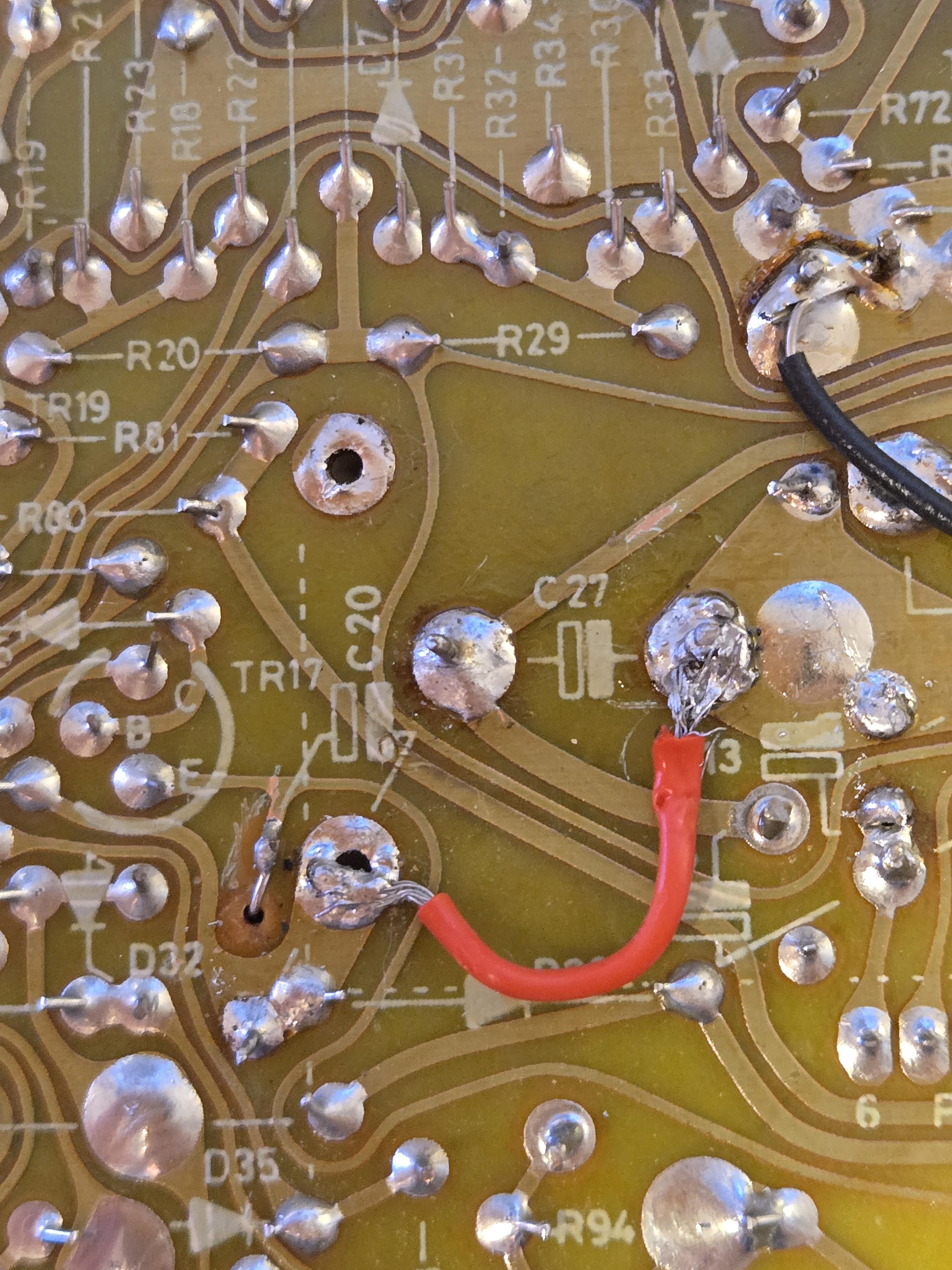
marchamBRONZE MemberIt lives! Happy to say that I have found signs of life.
I was poking around the board and found some odd signs of continuity around the C27 cap, so I decided to do some investigating. I swapped out C27 for the original cap, and now I have power to the board. This tells me that my method of testing capacitors is obviously faulty.
My meter doesn’t have a proper capacitance mode, so I was simply seeing if the cap would recharge and then discharge. This means I’ll be treating myself to a new meter with a capacitance setting and maybe even a little component tester to prevent this in the future.
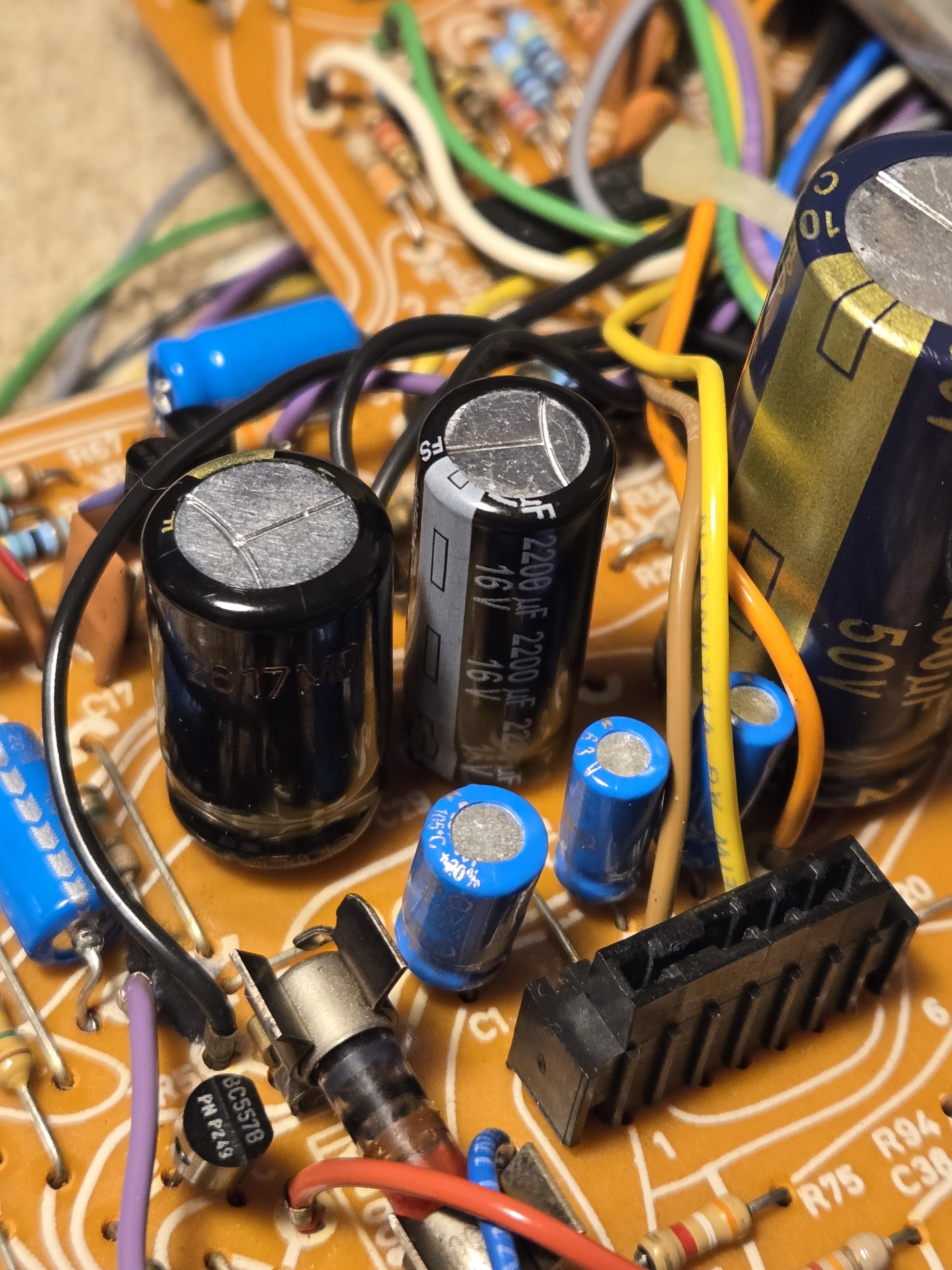
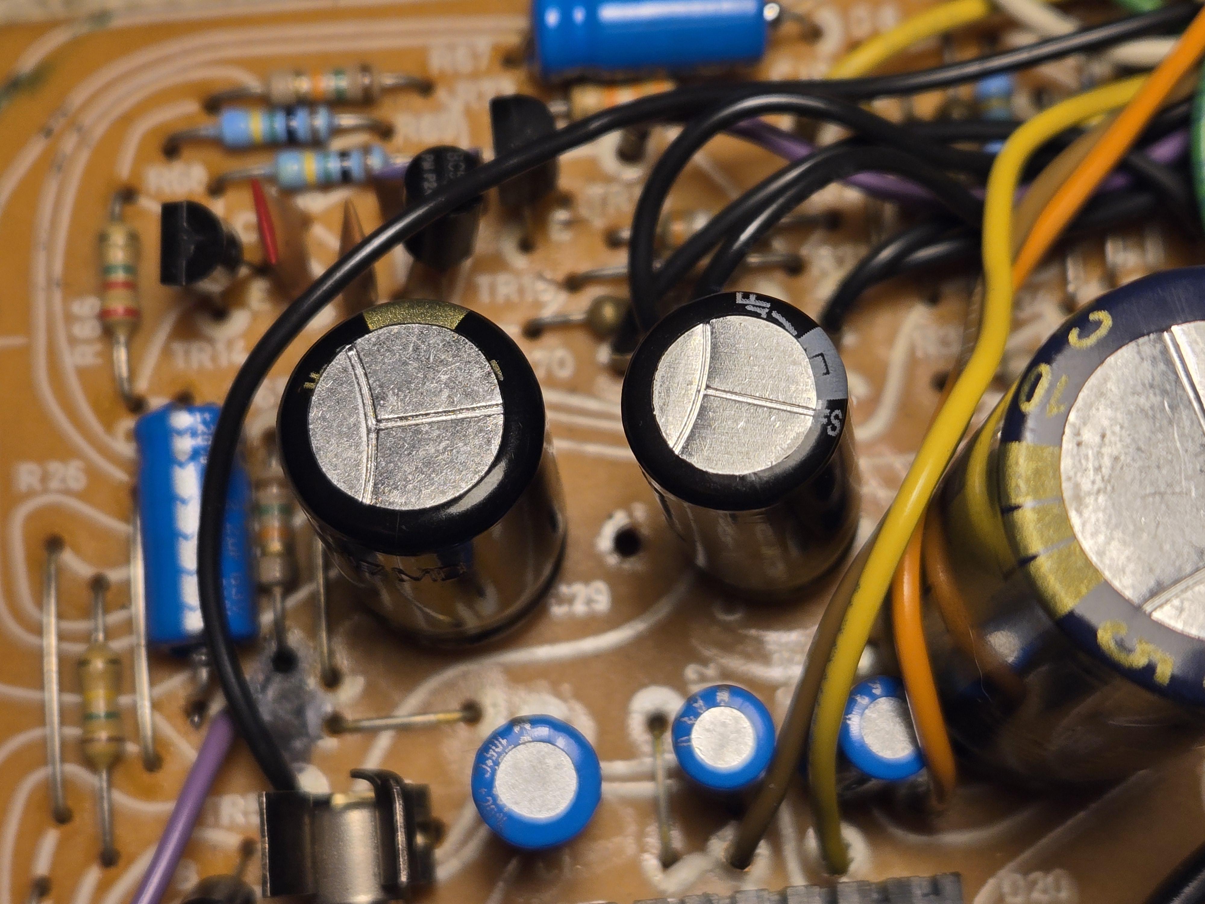
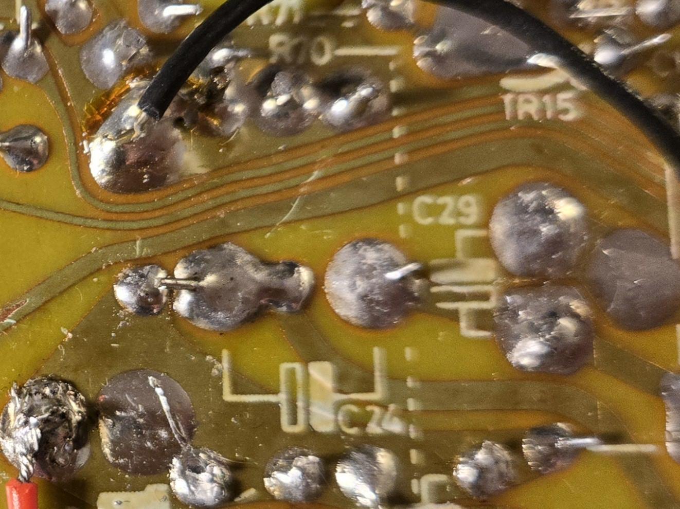
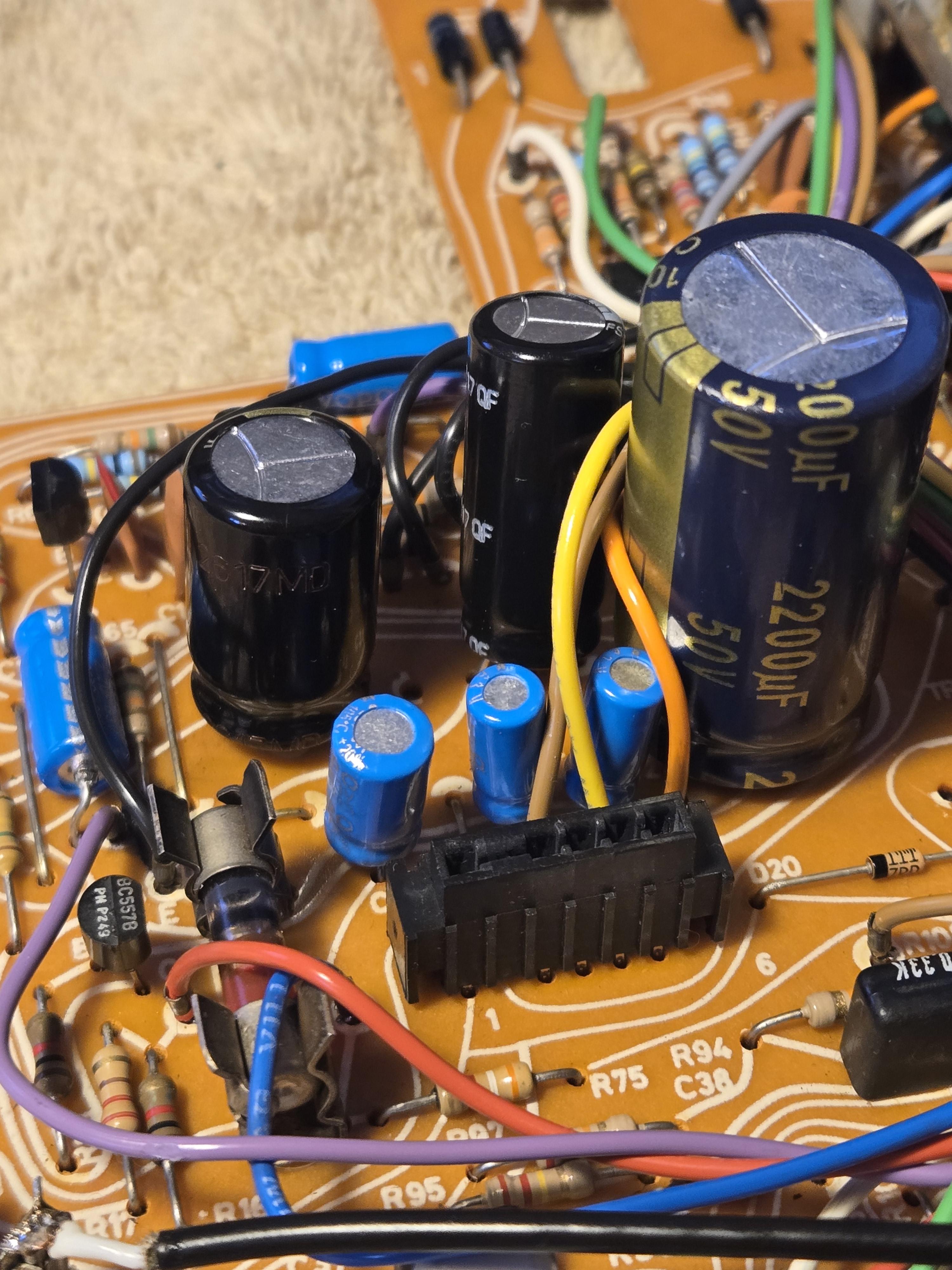
Anyway, not everything is working, but things are looking better. I still don’t get a standby LED, but a small light turns on near the tonearm and I can feel the motor warm up if I touch it. I’ve begun by testing all the caps to see the power flowing across them:
- C27: 22v
- C29: 23v
- C24: 12v
- 5v Regulator: 5v
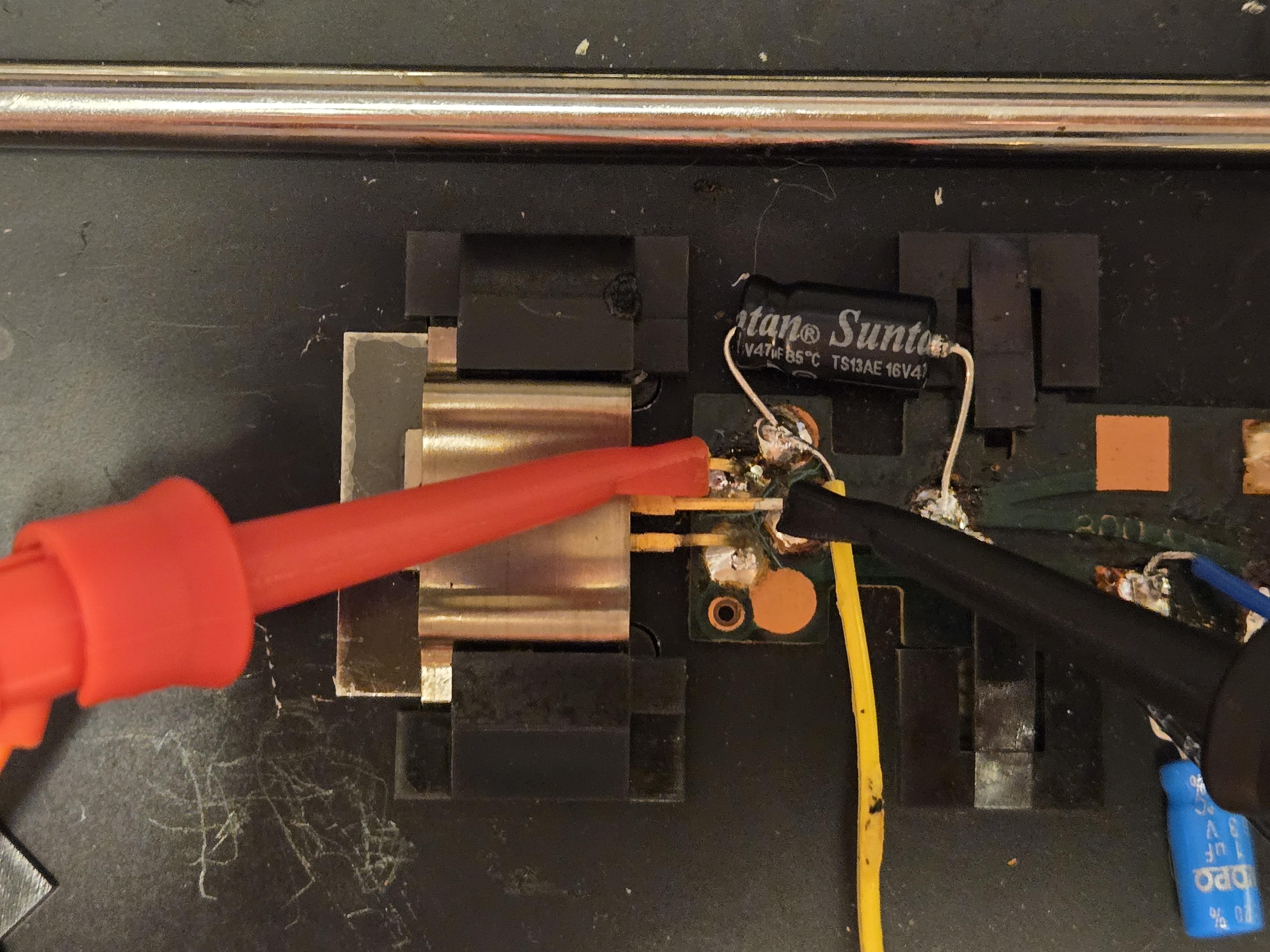
The one cap that doesn’t have proper power flow is the cap on PCB2. When measuring, the cap has 0V across it with the machine off and 0.5V across it with the machine on. I’m assuming this means it isn’t a ribbon connection problem. I also followed Beolover’s advice of snipping the ribbon to make it fit into the connectors better, and it does sit very firmly now.
I’ll see if I can work backwards, discovering why that cap on PCB2 isn’t getting the proper power, but if anyone has any advice in the meantime, feel free to let me know. Thanks, all!
Location: Pennsylvania, USA
Favourite Product: Beogram 3000
Signature: - Michael Archambault
My B&O Icons:
marchamBRONZE MemberThanks for the assistance, Spassmaker and Mark,
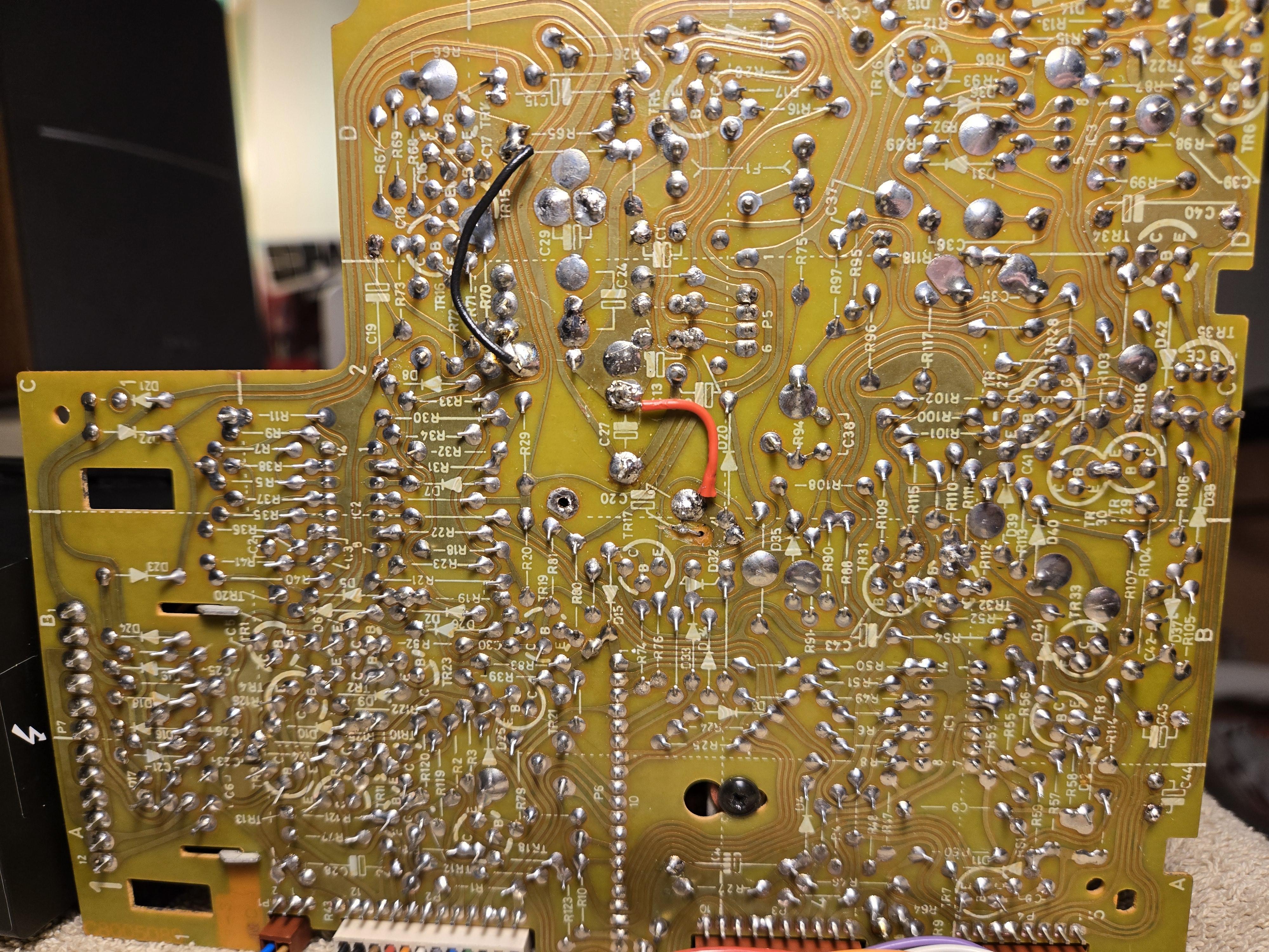
I checked D20 and D42, and both appear to operate as they should, with continuity in only one direction.
To double-check, is it normal or not to have continuity between P7-12 and P7-6? It sounds like I’m being told it’s normal due to the motor. This would make sense since the continuity between those two pins P7 pins only occurs when the P4 connector is plugged in.
Regarding checking 0c1, 0c2, and olc1, I’ve removed and checked these parts, which seems to operate fine. Although I don’t know if anything on this board would have an affect since the short occurs even with all connectors detached.
Shocked this simple capacitor swap out went down hill, but I can’t complain as I’m learning. Just want to find this short already.
Location: Pennsylvania, USA
Favourite Product: Beogram 3000
Signature: - Michael Archambault
My B&O Icons:
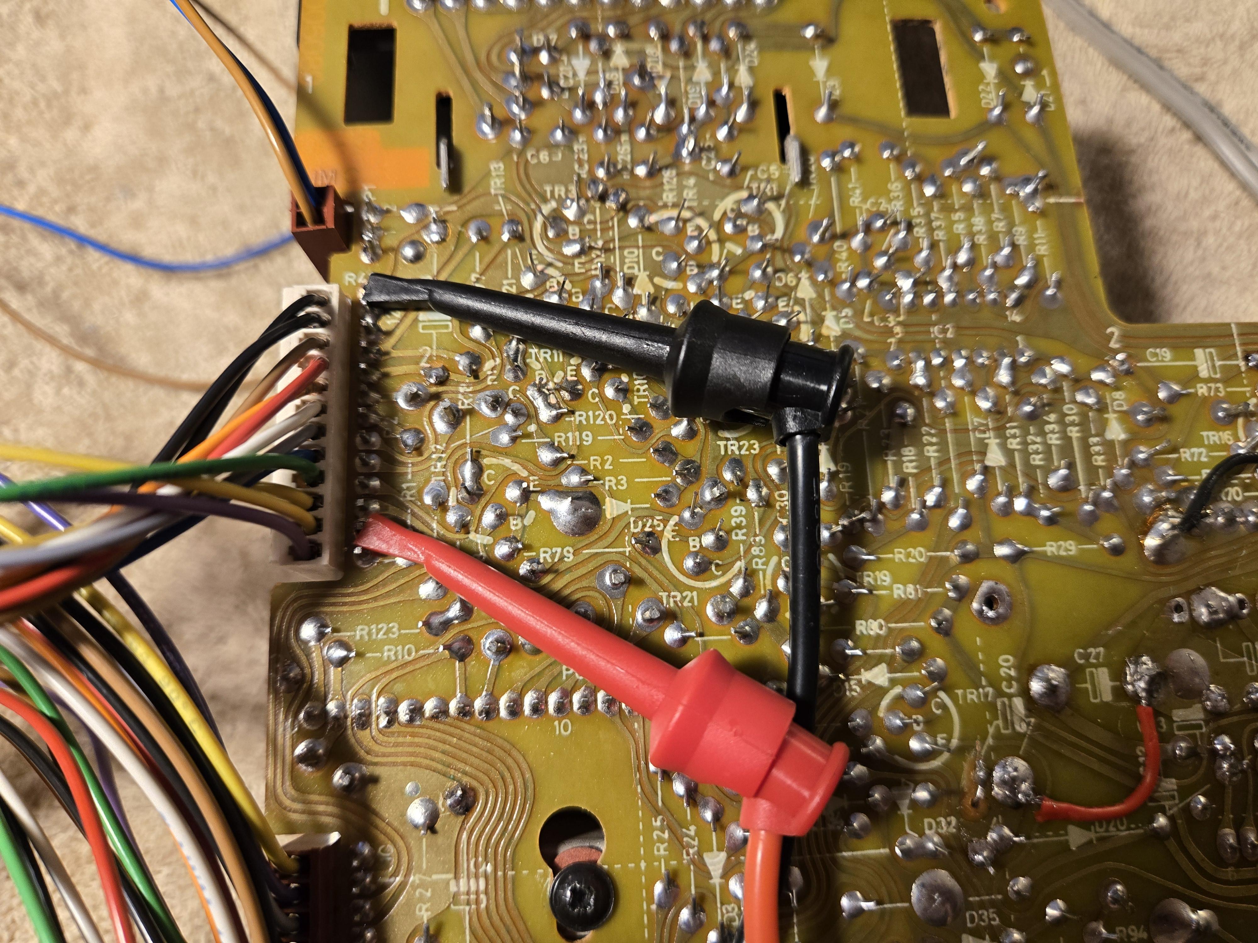
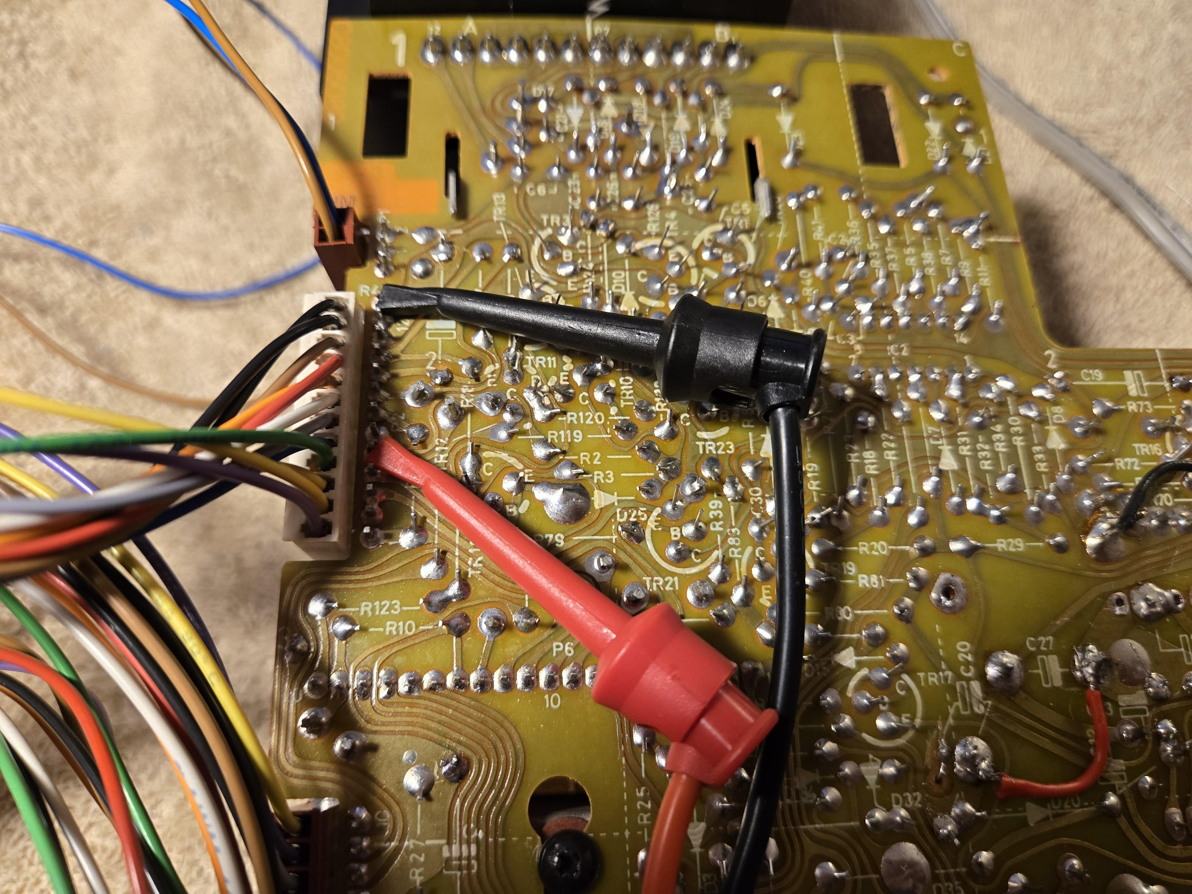
marchamBRONZE MemberUpdate: I retested the pins you suggested but left the other connectors plugged in. With this setup, pins P7-12 and P7-6 do have continuity.
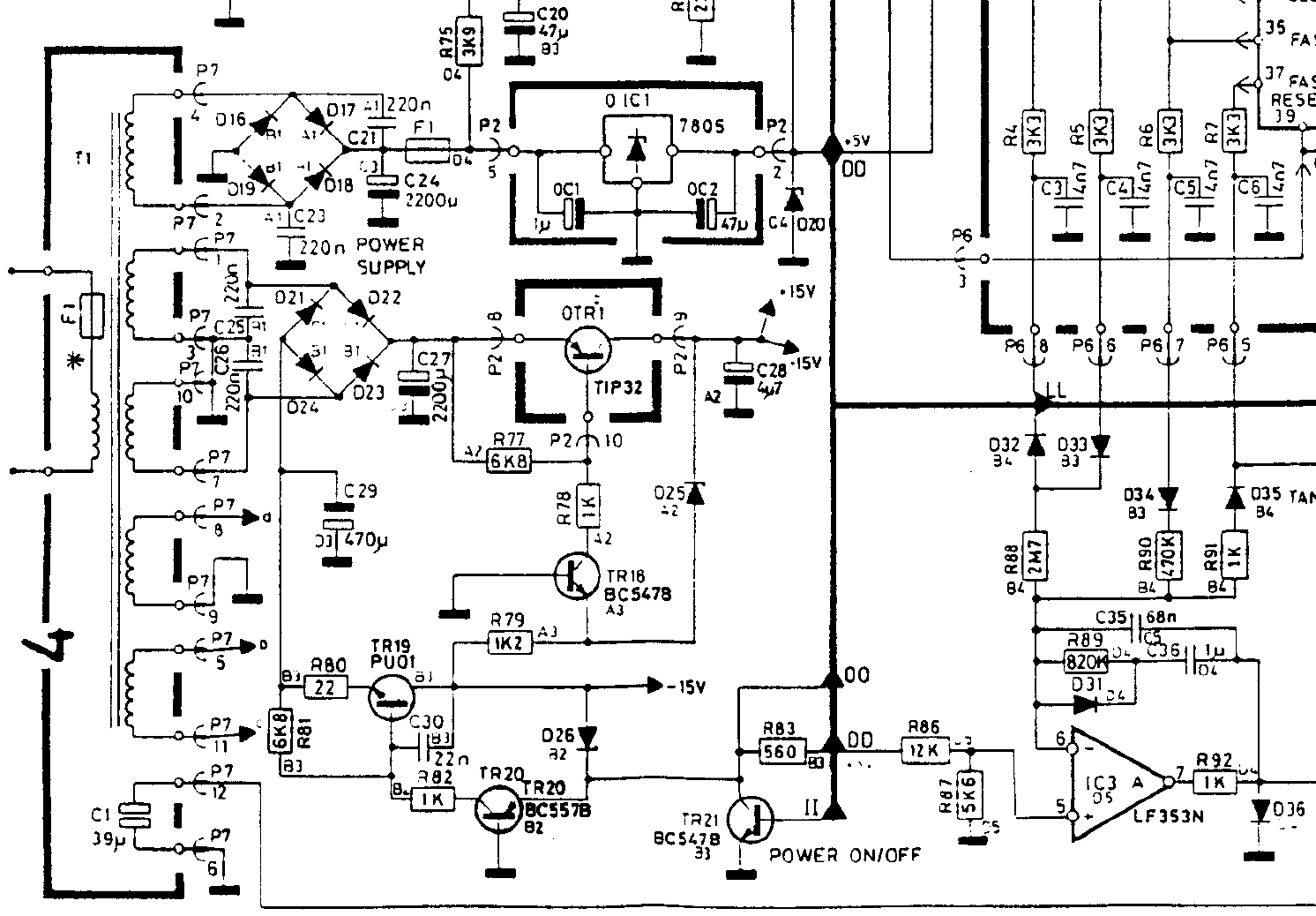
The schematic screenshot below shows where P7-12 leads; P7-6 goes to ground. The bottom-most path is from P-712, leading to D42 and a relay. Would you suggest following both paths and testing each component as I go, or is there a more efficient way to test?
Thanks!
Location: Pennsylvania, USA
Favourite Product: Beogram 3000
Signature: - Michael Archambault
My B&O Icons:
marchamBRONZE MemberThanks. I checked for continuity between the following P7 pins, and everything seemed fine: 4-2, 1-3, 10-7, 8-9, 5-11, and 12-6. No buzzes or resistance was shown; it was completely open.
Out of curiosity, I unplugged everything from the board so only the power supply and the main board were connected; it tripped. So, it is something on the main board.
I did my best to test the diodes in the two bridge rectifiers, but everything seemed to flow only in one direction, which looked good.
I think something happened when C27 or C24 was installed incorrectly or backward. I looked over the board for any signs of damage, but everything looks good, so I’m still lost.
Thanks again,
Location: Pennsylvania, USA
Favourite Product: Beogram 3000
Signature: - Michael Archambault
My B&O Icons:
marchamBRONZE MemberThe proper fuses (T300 mA/250V) arrived today; unfortunately, they blow when the power supply is connected to the board. The fuse is okay if I plug in the power supply without connecting it to the board, so I assume there is a short or something somewhere.
This is where my already limited knowledge hits a wall, so I’m hoping for any recommendations. My only thought would be to pull the caps for testing and then start testing the transistors and diodes. Any suggestions on where to start testing or specific components would be appreciated— any way to hunt this down without removing and testing so many components?

Thanks, all.
Location: Pennsylvania, USA
Favourite Product: Beogram 3000
Signature: - Michael Archambault
My B&O Icons:
marchamBRONZE MemberThanks for the help and tips everyone, I really appreciate it. I ended up going ahead and ordering a 300 mA slow blow fuse online, so hopefully I’ll have it in about a week. Once I pop that in, I’ll update everyone. Thanks again!
Location: Pennsylvania, USA
Favourite Product: Beogram 3000
Signature: - Michael Archambault
My B&O Icons:
marchamBRONZE MemberHi, all. Potentially good update on my end. After testing around a bit, I discovered at some point the fuse in the power supply went. I’m hoping once replaced, now that all caps are in the right spot, all will be good. Although I know there is a chance there could be damage elsewhere. Here’s my current question (no pun intended):
The fuse is a time delayed 300mA 250V. This has been challenging to find, but I can order it online and pay some hefty shipping ($10 on a $1 part) for slow delivery.
Or, I can grab an easier to find time delayed 500mA 250V fuse, which is available local and cheap. Could I go the second route without causing damage? Let me know if that’s a bad option.
Thanks, all!
ps – thanks for the tip on the cap placement, Dillen!
Location: Pennsylvania, USA
Favourite Product: Beogram 3000
Signature: - Michael Archambault
My B&O Icons:
marchamBRONZE MemberI appreciate all the advice from everyone.
The only capacitor that may have been inserted incorrectly at one time and powered up would have been C24.
When plugging everything in, I get no voltage across the following points.
Please let me know if I’m mismeasuring anything.
Thanks, all.


Location: Pennsylvania, USA
Favourite Product: Beogram 3000
Signature: - Michael Archambault
My B&O Icons:
marchamBRONZE MemberThanks, Glitch.
I tried both methods shown below, and neither worked. I’ve left it in the ‘A’ configuration that you suggested.
Here is the ‘A’ configuration that you suggested.


Here is the ‘B’ configuration I see for other repairs, such as Beolover.

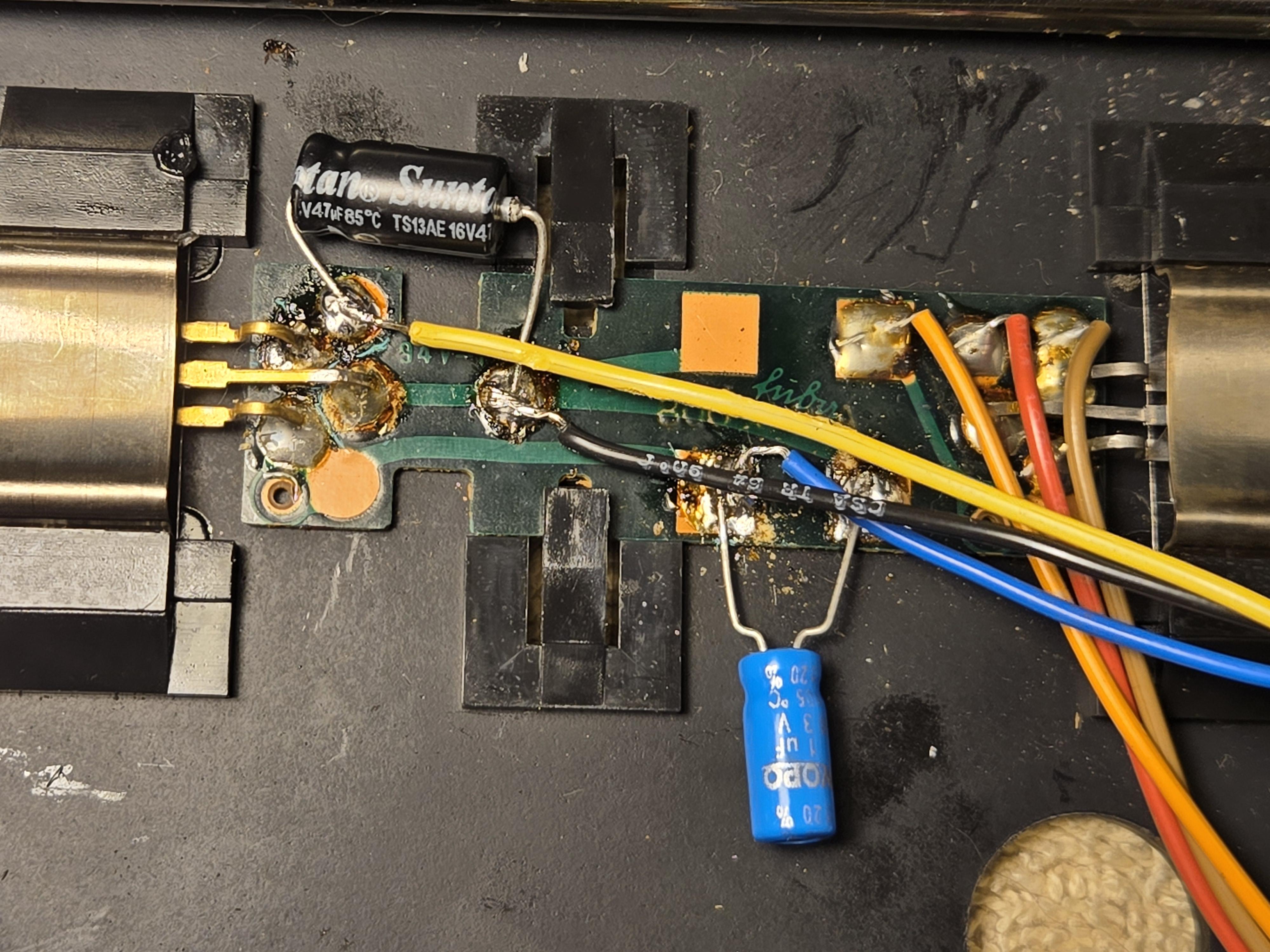
If I did want to test the power supply to ensure everything is working fine and test the 5V regulator, would you be kind enough to specify exactly where I should place my meter probes? Beolover provides a good guide for measuring across caps for the power supply, but I can’t see from his photo which legs of the transistor to attach to for 5V.
Thanks again for your help and time.
Location: Pennsylvania, USA
Favourite Product: Beogram 3000
Signature: - Michael Archambault
My B&O Icons:
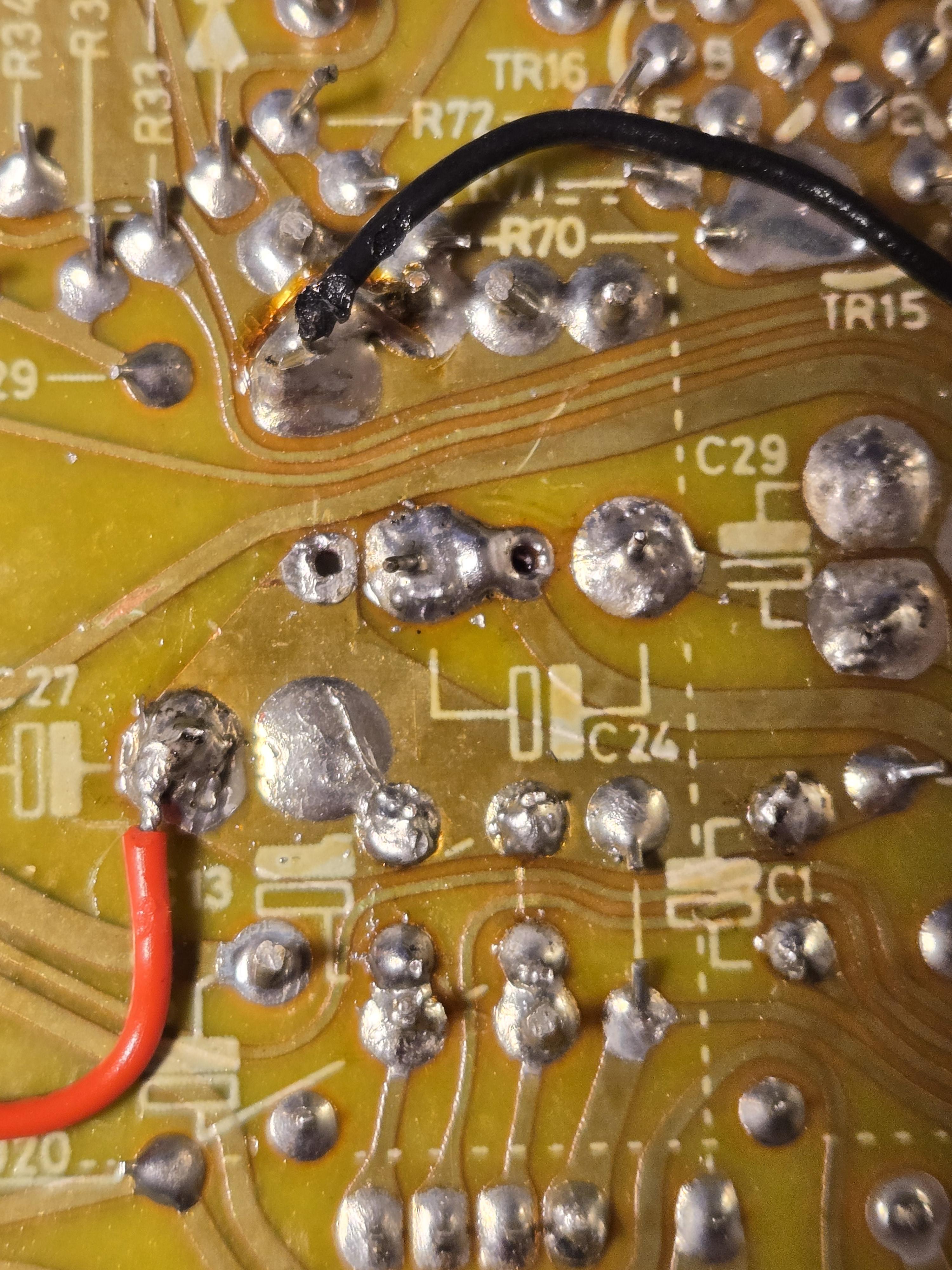
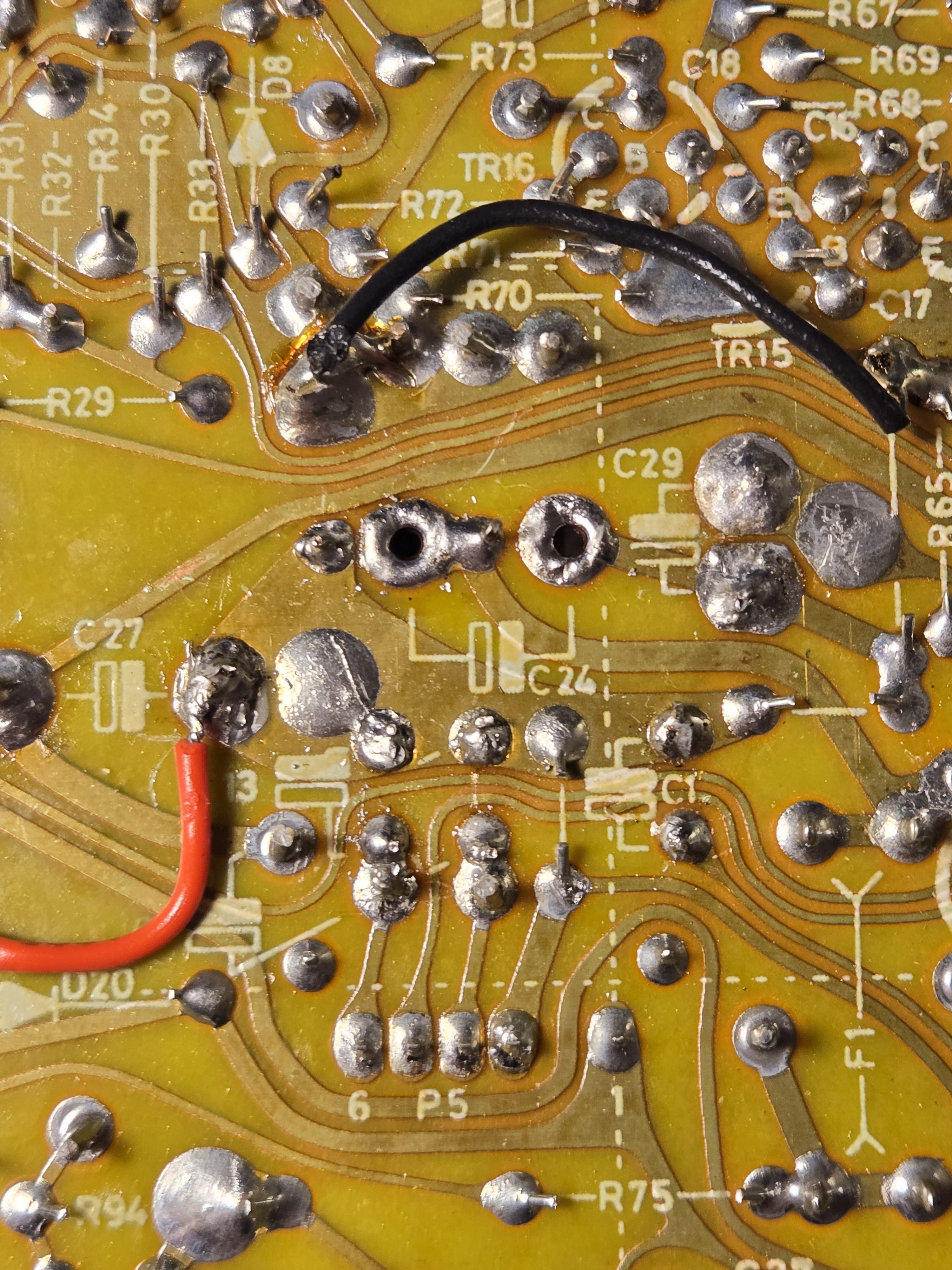
marchamBRONZE MemberHey Glitch, nice eye there! I’ve gone ahead and redone C24 as shown below. Another oddity that I noticed with this cap is that the board diagram shows reversed polarity compared to how the original was installed. Both the original cap and any repair work I have seen the other way. Thoughts?

Location: Pennsylvania, USA
Favourite Product: Beogram 3000
Signature: - Michael Archambault
My B&O Icons:
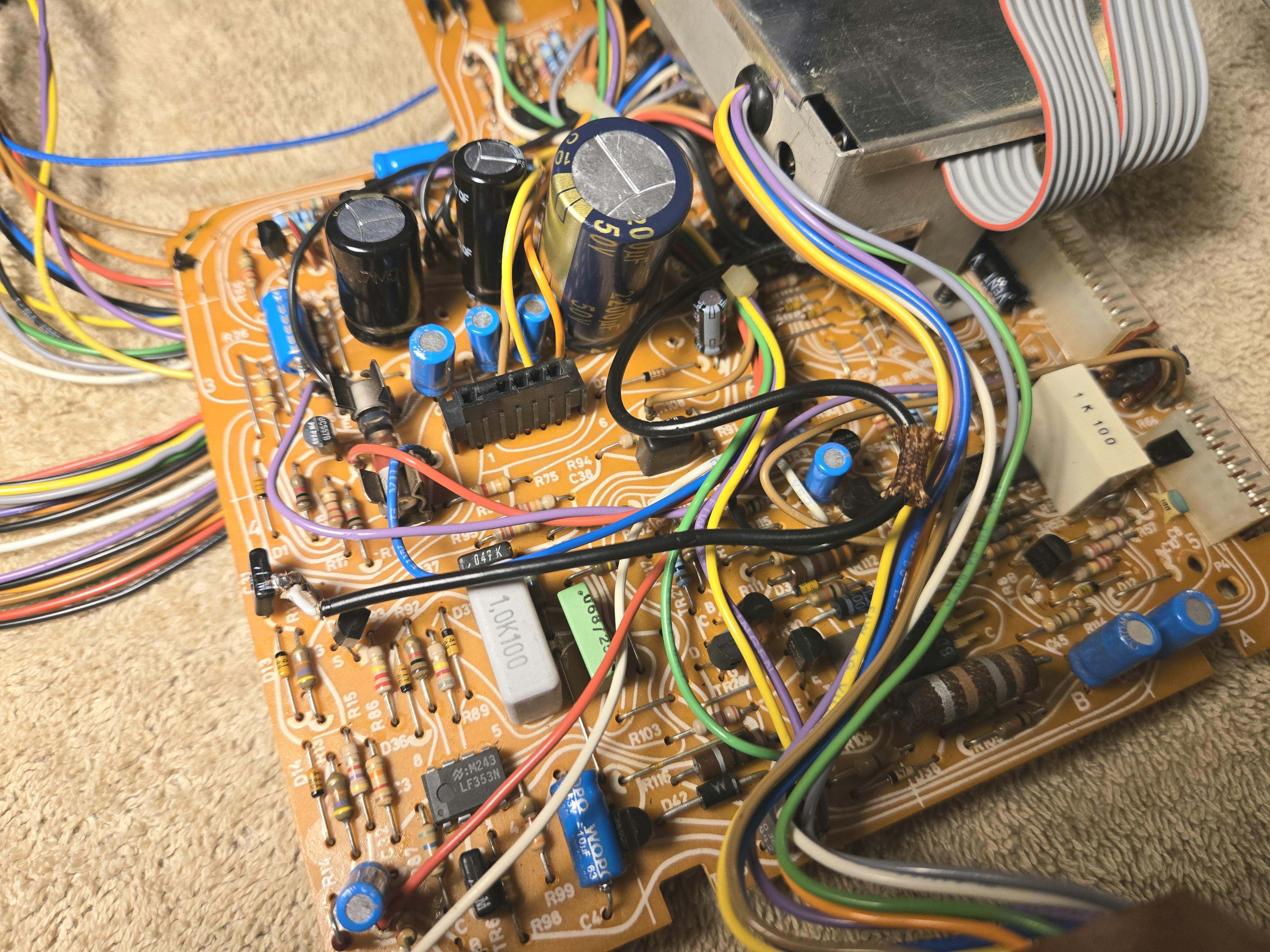
marchamBRONZE MemberI appreciate the advice, Glitch. I left the comment about not worrying about the soldering in my photo because I had an issue with my solder station and consistent temperatures. To show, I’ve retouched the board now that the station problem is resolved. I’ve also included photos of my recap job. Is it perfect? No, not at all, and I will keep practicing (I struggled a bit with the wire not being though-the-hole)! But it’s nowhere as bad as you might have thought initially. 🙂

Going back to the issue, I triple-checked my work: I looked for potential cracks, made sure the caps were installed with the correct polarity, and used a meter to test for continuity to ensure solid connections to points down the circuit— everything looked good. I also went through reflowing joints for all the major connectors. I think a component may have failed from excessive heat (I mentioned my solder station issue before), and I wonder if a cap has gone.
My plan at this point is to ensure power is flowing correctly, and I’ve been told that it starts with the 5V regulator. Any assistance or detailed steps to ensure the PSU delivers voltage and electricity flows would be welcome. I had to move the metal shield on the transistor I pointed out at one point, and I wanted to ensure the component is now working.
Location: Pennsylvania, USA
Favourite Product: Beogram 3000
Signature: - Michael Archambault
My B&O Icons:
marchamBRONZE MemberFollowing up with some additional information.
Found a post on Beolover about checking the power when the 8002 shows no sign of life. They recommended checking the 5V regulator first, but I’m not sure on how to measure it.
Any detailed instructions are welcome on testing the 5v regulator or the power in general. I have basic soldering skills and know how to probe with a multimeter, but my knowledge ends there.
Location: Pennsylvania, USA
Favourite Product: Beogram 3000
Signature: - Michael Archambault
My B&O Icons:
marchamBRONZE MemberThe way that I usually do this is to install the positive lead into the center hole and the negative lead into one of the (blue) holes that needs the jumper. The negative lead should be long enough to bend over to the other (blue) hole to act like a jumper. Just make sure it doesn’t short anywhere on the backside of the circuit board. GlitchThanks, Glitch. Apparently I installed it the wrong way the first time. I’ve included a photo; let me know if that’s what you were communicating. Ignore the bad looking solder job—it all holds up firm and has continuity. I’ll visually touch it up when I’m done. Unfortunately, now the machine isn’t giving me anything. When I first got it, it turned on, moved the tone arm half an inch, then shut off again. Told it needed new caps.Now, not even getting a standby light. Checked all the caps to make sure they’re in the correct orientation and there are no solder bridges, etc. All the fuses also look good.Primary concern are the connectors that are bare metal into black slots (like the two running from the CPU PCB to the main board). They fit into their respective spots and are pushed all the way down but aren’t really secure and slide right out if given the chance.Any thoughts? Thanks for any help!
Location: Pennsylvania, USA
Favourite Product: Beogram 3000
Signature: - Michael Archambault
My B&O Icons:
-
AuthorPosts