Forum Replies Created
-
AuthorPosts
-
 marchamBRONZE Member
for anyone with the same issue I found a suitable replacement from a great little shop in the midwest.
MW Audio MT-4115: 1 inch Dome Tweeter:
https://www.midwestspeakerrepair.com/product/mw-audio-mt-4115-1-inch-dome-tweeter/
Thanks for sharing! Nice to know someone makes replacements. I completely rebuilt my S75s last year and couldn’t find new tweeters in the correct ohms. I ended up ordering new diaphragms from China and installing them myself. Good to know these exist!
Location: Pennsylvania, USA
Favourite Product: Beogram 3000
Signature: - Michael Archambault
My B&O Icons:
 marchamBRONZE Member
Hey, Glitch. Yep, I’m stubborn and refuse to put this machine down. 😅
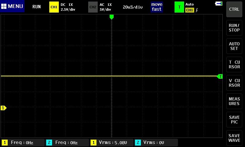
Checked out the display strobe pins on the scope, and don’t get anything besides a flat 5V signal.

The issue with -15V rail was down to a bad TR19. I had replaced the TR19 with a new PU01, but turns out I must have gotten a counterfeit from eBay. When popping it in my component tester, it recognized the transistor, but backwards; as in the case was labeled EBC, but was actually arranged CBE. I flipped it around, and it seems to work without issue for now. Still going to get a proper replacement from Danish Sound Shop in the future.
Location: Pennsylvania, USA
Favourite Product: Beogram 3000
Signature: - Michael Archambault
My B&O Icons:
marchamBRONZE MemberEvening, all.
I was able to track down the issue for my last problem and now have my +15V, -15V, and +5V rails. 👍
However, I still have problems with the unit and suspect the CPU. Current problems include a constantly spinning turntable, no response to keyboard input, and a display that goes between showing one dot and multiple dots. I’ve confirmed the keyboard presses do take the appropriate pins low.
Here are my readings; does all look okay from the CPU side of things?
- PIN # 1, 5V, DATA LINK
- PIN # 2, 5V, KB: PLAY
- PIN # 3, 5V, KB: STOP
- PIN # 4, 5V, KB: DOWN
- PIN # 5, 5V, KB: UP
- PIN # 6, 5V, KB: 45
- PIN # 7, 5V, KB: 33
- PIN # 8, 5V, KB: PAUSE
- PIN # 9, 4V, DATA LINK
- PIN # 10, 2V, CRYSTAL
- PIN # 11, 2.3V, CRYSTAL
- PIN # 12, 0V, GROUND
- PIN # 13, 5V, DIGIT SELECT OUT
- PIN # 14, 5V, DIGIT SELECT OUT
- PIN # 15, 0V, DIGIT SELECT OUT
- PIN # 16, 5V, DIGIT SELECT OUT
- PIN # 17, 5V, BCD OUT
- PIN # 18, 5V, BCD OUT
- PIN # 19, 5V, BCD OUT
- PIN # 20, 5V, BCD OUT
- PIN # 21, 5V, ?
- PIN # 22, 3.5V, INDICATOR
- PIN # 23, 5V, KB: TURN
- PIN # 24, 2.5V, LIFT
- PIN # 25, 5V, <<
- PIN # 26, 5V, >>
- PIN # 27, 5V, SLOW <<
- PIN # 28, 3V, SLIDE TACHO
- PIN # 29, 3V, SLIDE TACHO
- PIN # 30, 5V, 5V
- PIN # 31, 0V, LIFT MANUAL
- PIN # 32, 0V, SO
- PIN # 33, 5V, DISC DETECTOR
- PIN # 34, 5V, SLOW DOWN
- PIN # 35, 5V, FAST UP
- PIN # 36, 0V, SLOW UP
- PIN # 37, 5V, FAST DOWN
- PIN # 38, 2.5V, POWER ON/OFF
- PIN # 39, 4.5V, RESET
- PIN # 40, 0V, SPEED SENSOR
Note that PIN 38 is sitting at 2.5V (is that correct?); I thought it should be either 0V or 5V.
The same comment goes for a few other pins. I thought it would be either low (0V) or high (5V).
Thanks.
Location: Pennsylvania, USA
Favourite Product: Beogram 3000
Signature: - Michael Archambault
My B&O Icons:
marchamBRONZE MemberHey, all.
Thanks for sticking with me on this multi-month journey; I’ve been learning more than you can imagine.
The good news is that I finally have a standby light after solving some communication issues between the PCB and PCB2 and fixing the bad Molex connectors. The ‘bad news’ is that I’m troubleshooting the 15V circuit and am a bit stuck.
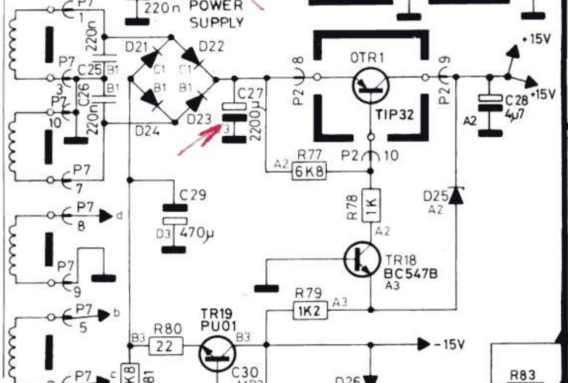
I’m suddenly not getting a +15V signal, so I’m investigating the appropriate area of the circuit. I believed OTR1 (TIP32) might be bad, so I swapped it out with a brand-new TIP32C.
I get a solid 23V signal from D21-24, across the leg of C27, and straight to P2-8. However, the measurements of OTR1 show 23V at both the base and emitter. The collector and P2-9 are sitting at 0V.
I’ve swapped out OTR1 for another TIP32C, even though it tests fine and has the same result. I’ve even swapped out R77, thinking it could have been bad despite testing fine, but the issue remains.
Other notes of worth:
+ Measuring between P2-8 and P2-10 shows 6.8k Ohms as it should.
+ TR18 has 23V at its collector. 0V at the emitter and base. It recently tested fine.
+ Removing OTR1 and testing the board shows no issues with unexpected connectivity.
+ D25 is tested and working fine.
+ C27 and C28 test fine.What am I missing here? Is OTR1 at fault? Is the TIP32C not a solid replacement? I’m still trying to wrangle proper resistor drops, as both sides of R77 measure about the same (23V), so it doesn’t seem to do much.
Thanks, all.

Attachments:
You must be logged in to view attached files.Location: Pennsylvania, USA
Favourite Product: Beogram 3000
Signature: - Michael Archambault
My B&O Icons:
marchamBRONZE MemberThanks, Mark! Someone on Reddit had suggested this as a replacement, so I’ll grab a few new connectors and clips.
https://www.digikey.com/en/products/detail/molex/0022012121/1090462
https://www.digikey.com/en/products/detail/molex/0008650805/1130600
Location: Pennsylvania, USA
Favourite Product: Beogram 3000
Signature: - Michael Archambault
My B&O Icons:
marchamBRONZE MemberBit of an update. After wondering why my progress regressed, I decided to go through and test the basics (aka power). I found that the 15V line wasn’t producing voltage and quickly traced it back to a loose connection on the P2 connector.
This harkens back to one of the original problems I had when I started working on the unit. Wires started coming loose from the P2 connector. I attempted to fix this by reinserting the wires and using hot glue to hold them in place. While ‘okay,’ this solution hasn’t been great and isn’t producing the most stable connection.
Does anyone have any recommendations on where to find replacement Molex connectors for the wires? I can’t find the exact replacement anywhere.
I also tried removing the metal pins from the connector to reattach the wires correctly, but I couldn’t remove them.
Thanks, all.
Location: Pennsylvania, USA
Favourite Product: Beogram 3000
Signature: - Michael Archambault
My B&O Icons:
marchamBRONZE MemberHey, all. Replaced TR17, but nothing changed.
To confirm the current situation, the display shows four dots and pressing ‘Start’ displays ’33,’ but nothing starts up.
Also, to double check, should the state of each keyboard button be high by default at the CPU, then go low when pressed? That’s the current state at the moment.
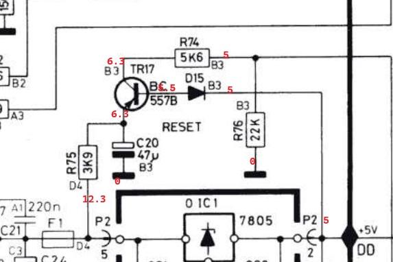
Included some readings from the reset section below. It remains high at CPU pin 39 at all times.
Thanks!

Location: Pennsylvania, USA
Favourite Product: Beogram 3000
Signature: - Michael Archambault
My B&O Icons:
marchamBRONZE MemberHey Dillen. Thanks, appreciated!
I’ll have to research my understanding of transistors, as I thought TR17 looked good.
I thought that if the B was powered (5V), C and E should be open with the same voltage (6V).
I ordered a new bc557b transistor and it will be here tomorrow to swap out.
Thanks again.
Location: Pennsylvania, USA
Favourite Product: Beogram 3000
Signature: - Michael Archambault
My B&O Icons:
marchamBRONZE MemberHey, all! The swap of 01C1 was successful in moving forward the repair. Everything receives the correct power: 5V, 15V, and -15V. However, the unit doesn’t want to start up properly. After experimenting, I found that the unit has a constant 5V at pin #39 (reset); I assume this should go low when switched on.
I can confirm that hitting the ‘Play’ button does reach the CPU. I dove into the reset circuit, but everything seems fine. All resistors test fine, the cap (C20) tests fine, the diode (D15) is OK, and so is the transistor (TR17). The base gets a constant 5V, while the emitter and collector are around 6V.
I’m a bit confused about this. I assume that the base shouldn’t be 5V at all times, but where does the signal come from? The base only goes to D15, directly from around P2(2), which seems like it would always have a constant 5V. What am I missing?
Thanks!
Location: Pennsylvania, USA
Favourite Product: Beogram 3000
Signature: - Michael Archambault
My B&O Icons:
marchamBRONZE MemberUnderstood, replacing it. Thank you, Dillen! I will report back once the replacement part has arrived and been installed.
If you have a moment for me to learn, why this recommendation? In my beginner’s eyes, it appears 0TR1 is working right, and the wrong voltage is being sent to the base during standby, meaning a different component is at fault. So why replace OTR1?
Thanks as always!
Location: Pennsylvania, USA
Favourite Product: Beogram 3000
Signature: - Michael Archambault
My B&O Icons:
marchamBRONZE MemberThanks for clarifying, Dillen.
These readings were taken in the standby state.
Here is how the states change between standby on/off:
Standby: E:20V, B:14V, C:14V
On: E:20V, B:13V, C:13V
I should note, the platter spinning in standby is not a ‘slow’ spin, but quite fast.
Additionally, the Play/Stop buttons work intermittently.
Location: Pennsylvania, USA
Favourite Product: Beogram 3000
Signature: - Michael Archambault
My B&O Icons:
marchamBRONZE MemberHey Martin, I really appreciate the response.
Let me know if I’m misunderstanding your suggestion, but the 15V rail seems to work perfectly; it’s only the -15V that is MIA.
Here is a copy of the circuit readings I previously provided. 0TR1 seems to be working fine.
As for a break, do you see anything odd within the circuit readings?
Hoping between these and the section included above, they hold a clue.
Thanks again!

Location: Pennsylvania, USA
Favourite Product: Beogram 3000
Signature: - Michael Archambault
My B&O Icons:
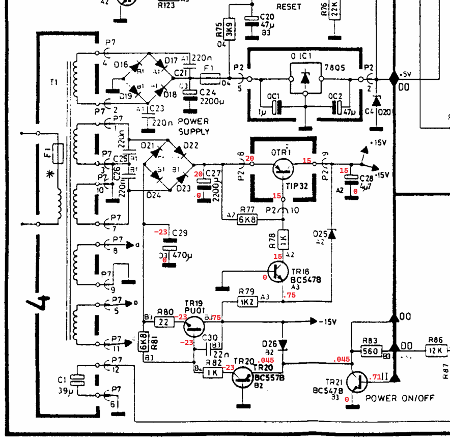
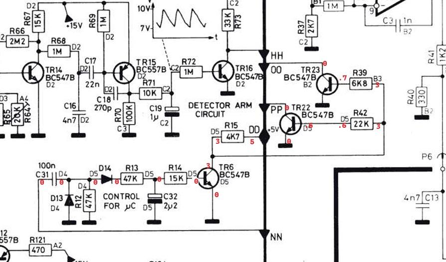
marchamBRONZE MemberI’m adding more information in the hope that someone can help me with the missing -15V rail. Three lines leading away from the power section, near TR21, are 00, DD, and II.
Tracing down II leads to the CPU outputting either 0V or 2.5V via the On/Off pin.
DD connects to the +5V supply and leads to an upper section that I have included below with readings. 00 also leads to this upper section, and I have included the readings as well.
From 00 is PP, which leads to the braking circuit. It feels like I’m getting close, as another problem right now is a constantly spinning platter.
From DD is NN, but that appears to lead to ground.
As always, any help is appreciated, thanks!

Location: Pennsylvania, USA
Favourite Product: Beogram 3000
Signature: - Michael Archambault
My B&O Icons:
marchamBRONZE MemberJust popping in with an update.
Still at the same point but been poking around the board and reading voltages.
I noticed that the main chip’s voltage on pin #38 (on/off) swaps between 0V and 2.5V. However, the chip seems to be getting its primary 5V at pin #30 without issue, so could the chip be the issue in any way? I tried reseating it, but it did not change.
Poking around TR19 and TR21 trying to figure out why there is still no -15V signal. I feel that’s the heart of the issue.
Thanks, all.
Location: Pennsylvania, USA
Favourite Product: Beogram 3000
Signature: - Michael Archambault
My B&O Icons:
marchamBRONZE MemberHey Glitch, Thanks for the explanation; that makes sense.
Looking into TR21, the signal sits at .71V in standby and drops to .08V when switched on with the tonearm in motion. All readings in the diagram were taken in standby mode.
To help visually, I recorded a short two-minute video.
Location: Pennsylvania, USA
Favourite Product: Beogram 3000
Signature: - Michael Archambault
My B&O Icons:
marchamBRONZE MemberAfternoon, all. Hope everyone is having a good holiday.
I had the time to dive in and take more voltage readings.
As someone who doesn’t know exactly how a circuit flips a voltage from 15V to -15V, I would say that something looks a bit off around TR18, even though that transistor tested well. But, again, what do I know? 🙂
Any insight appreciated. Thanks, all!
Location: Pennsylvania, USA
Favourite Product: Beogram 3000
Signature: - Michael Archambault
My B&O Icons:
marchamBRONZE MemberThanks for the info, Glitch. Checking at TR21, there is no voltage when the Beogram is on or off. If I check pin 38 of the CPU, the voltage is 2.5V when off and 0V when switched on. I can confirm that 5V is making it to the CPU at pin 30. As for C29, the voltage stays stable at all times around 24V. I’m not sure if this helps illuminate a picture.
I’ll try to test some other areas within the circuit, but hopefully, the above is a clue. Seeing it connected in the block diagram, I also tested transistors TR6, TR22, and TR23 — all look good.
I’m trying to find a fault that would cause the display to always show four red dots and the table to constantly spin at a slow speed, even when off.
Location: Pennsylvania, USA
Favourite Product: Beogram 3000
Signature: - Michael Archambault
My B&O Icons:
marchamBRONZE MemberHey, Glitch (and others),
It has been a while since I popped into this thread, as I’ve had some of my projects on hold. I was waiting on parts for the Beogram and then had to solve an issue with the ribbon cable connecting PCB2. Luckily, all that has been handled, and I’m down to troubleshooting what is hopefully the last issue, and I need a bit of assistance.
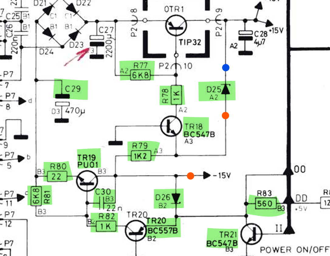
Long story short, there is an issue with my -15V rail; I’m getting 5V and 15V fine, but the -15V is nonexistent. I’ve uploaded a photo of the schematic for additional detail. Red spots are where I have tested for voltage and only received around .75 V. The blue spot is an example of a place I tested and received +15V. The components highlighted in green appear to be working when tested.

Any thoughts? I figured if there were an issue with the 15V rail, I would find it in one of these highlighted components. Any advice?
Thanks, all,
Location: Pennsylvania, USA
Favourite Product: Beogram 3000
Signature: - Michael Archambault
My B&O Icons:
marchamBRONZE MemberI appreciate the feedback, Dillen. Luckily, I got everything sorted out!
I am posting the solution here in case anyone else has the same issue. I solved the problem by better isolating the tweeter diaphragms’ speaker wires. When replacing the diaphragms, the wires must run down a metal channel on the front of the tweeter plate. I was isolating the wires in this channel with heat shrink tubing, but I also needed to ensure the thin wires weren’t coming into contact with the edges of the round center cutout.
You can prevent contact with very thin heat shrink tubing or electrical tape.
Location: Pennsylvania, USA
Favourite Product: Beogram 3000
Signature: - Michael Archambault
My B&O Icons:
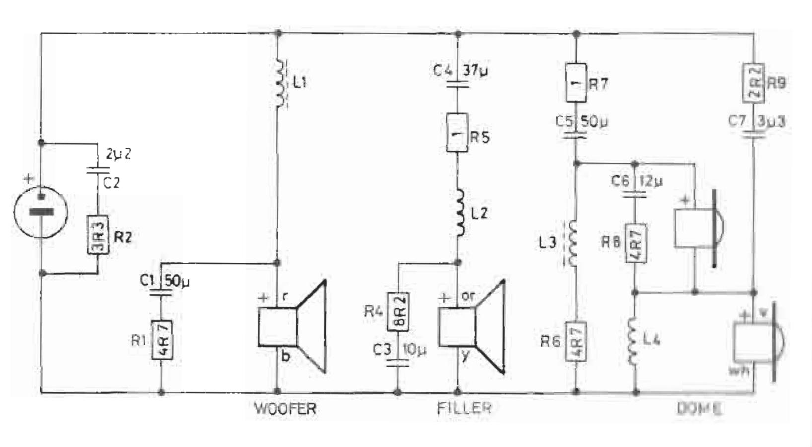
marchamBRONZE MemberPosting in the crossover schematic. While I redid the caps, everything else is original. As I mentioned, I redid the tweeters with new diaphragms, but I would assume a signal is getting to them that shouldn’t, making it the crossovers.

Location: Pennsylvania, USA
Favourite Product: Beogram 3000
Signature: - Michael Archambault
My B&O Icons:
-
AuthorPosts