Forum Replies Created
-
AuthorPosts
-
18 January 2026 at 19:29 in reply to: Beomaster 3000-2 Type 2402 15V Power Supply Not Activating #72694
 Johnny LawBRONZE Member
Quick follow-up … I completely forgot that the tuner alignment section of the manual specifies the correct voltage at #47. It’s 4.5V for 104MHz units and 4.2V for 108MHz units. So I dialed mine into 4.2V and … that’s all I can do without an FM signal generator for now.
Happy side effect of fiddling with the FM front end, the static in stereo went away. I’ll call it a win and put the case back on.
16 January 2026 at 19:46 in reply to: Beomaster 3000-2 Type 2402 15V Power Supply Not Activating #72603Johnny LawBRONZE MemberThanks for trying Craig … let me know if I can help at all with yours … maybe by the time this thread reaches its conclusion we’ll get not 1 but 2 working 3000-2s!
15 January 2026 at 18:48 in reply to: Beomaster 3000-2 Type 2402 15V Power Supply Not Activating #72582Johnny LawBRONZE Member
(Just kidding – I take spiders outside and let em go too!)
15 January 2026 at 01:21 in reply to: Beomaster 3000-2 Type 2402 15V Power Supply Not Activating #72557Johnny LawBRONZE MemberFor reference, measuring at the FM front-end side of inductor #47 I am seeing the following range of voltages from lowest FM frequency to highest: ~4.3V to ~19.0V. Same for FM and each of the 6 presets.
Is that correct?
14 January 2026 at 18:11 in reply to: Beomaster 3000-2 Type 2402 15V Power Supply Not Activating #72548Johnny LawBRONZE MemberI should add, I verified that my 22V power supply is good.
Also, the 6 FM presets are the same … they are limited to the same narrow frequency range as the main FM mode, leading me to believe that 129 and 132 are both OK as well as all of the 0.47uF tants (which are original and have not been measured or replaced). But – I could be wrong.
14 January 2026 at 18:08 in reply to: Beomaster 3000-2 Type 2402 15V Power Supply Not Activating #72547Johnny LawBRONZE MemberThe first FM problem: the tuner has lost the 88 – 108 MHz range. It tops out around 105MHz on the top end and around 89MHz on the low end.
I can fiddle with the local oscillator in the FM front end to shift the range up and down, but it always stops short of receiving the entire public broadcast FM spectrum.
I am wondering if this is a symptom of the inductive coupling between the FM pot and the FM front end’s LO falling apart?
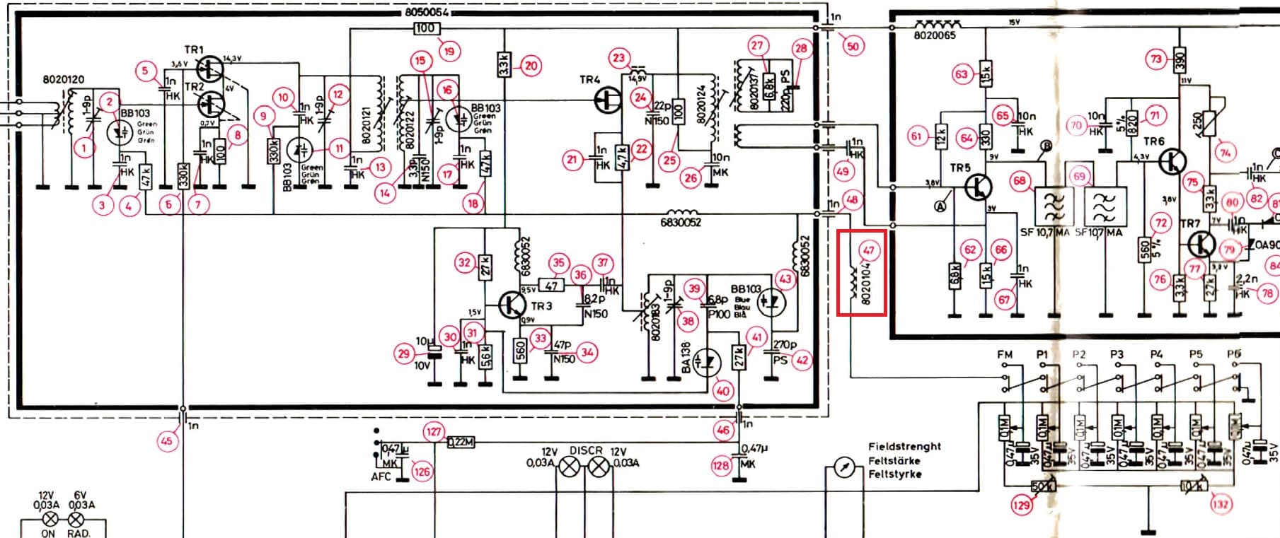
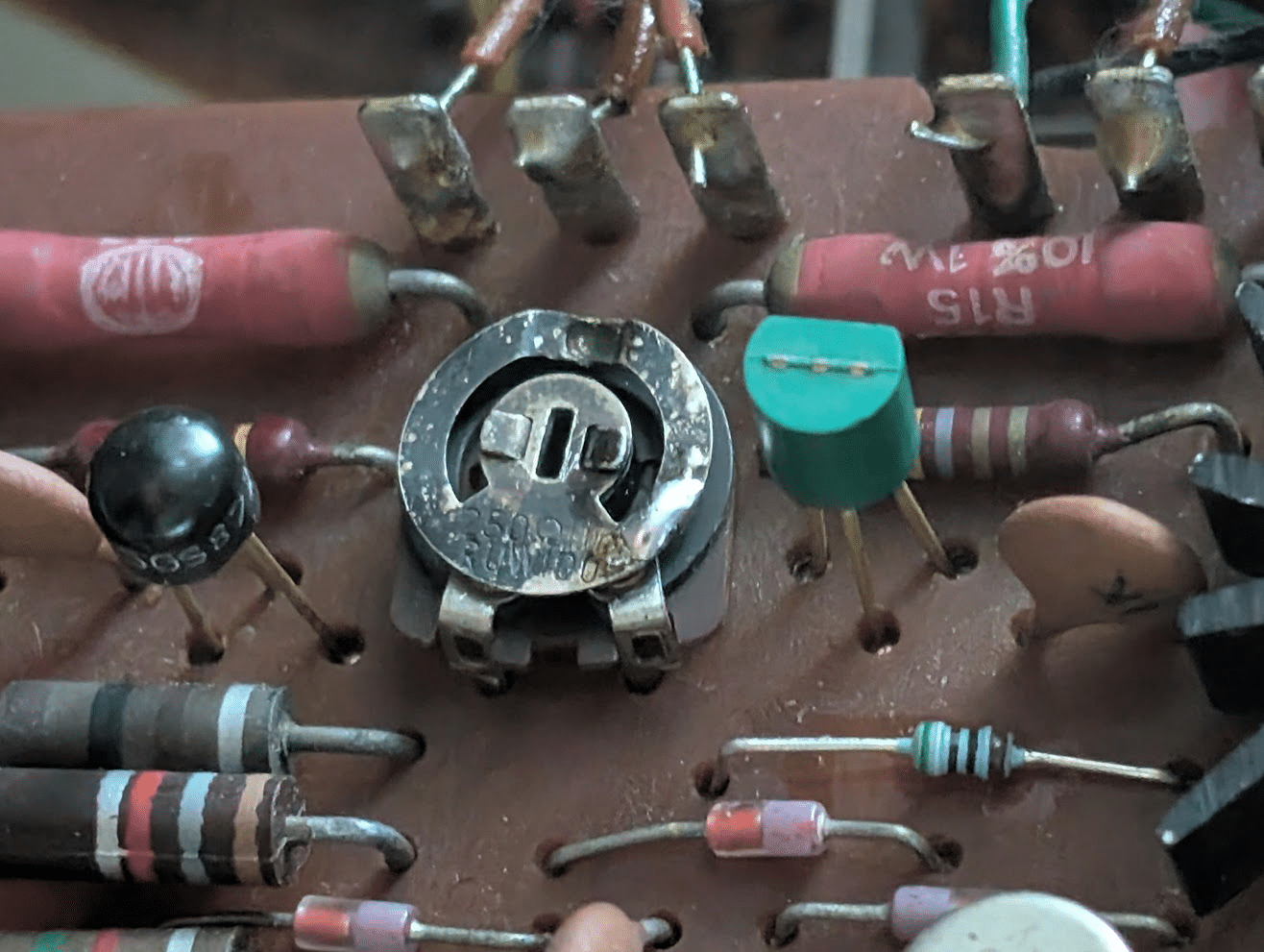
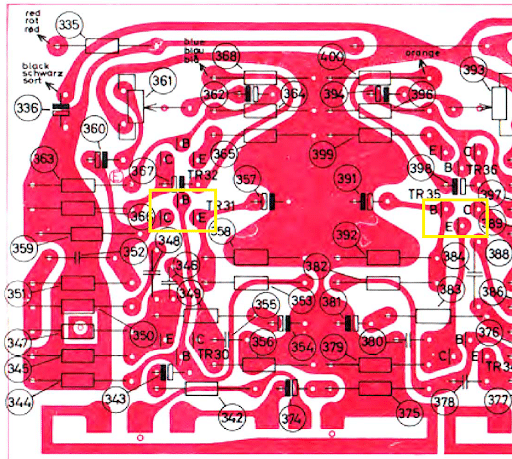
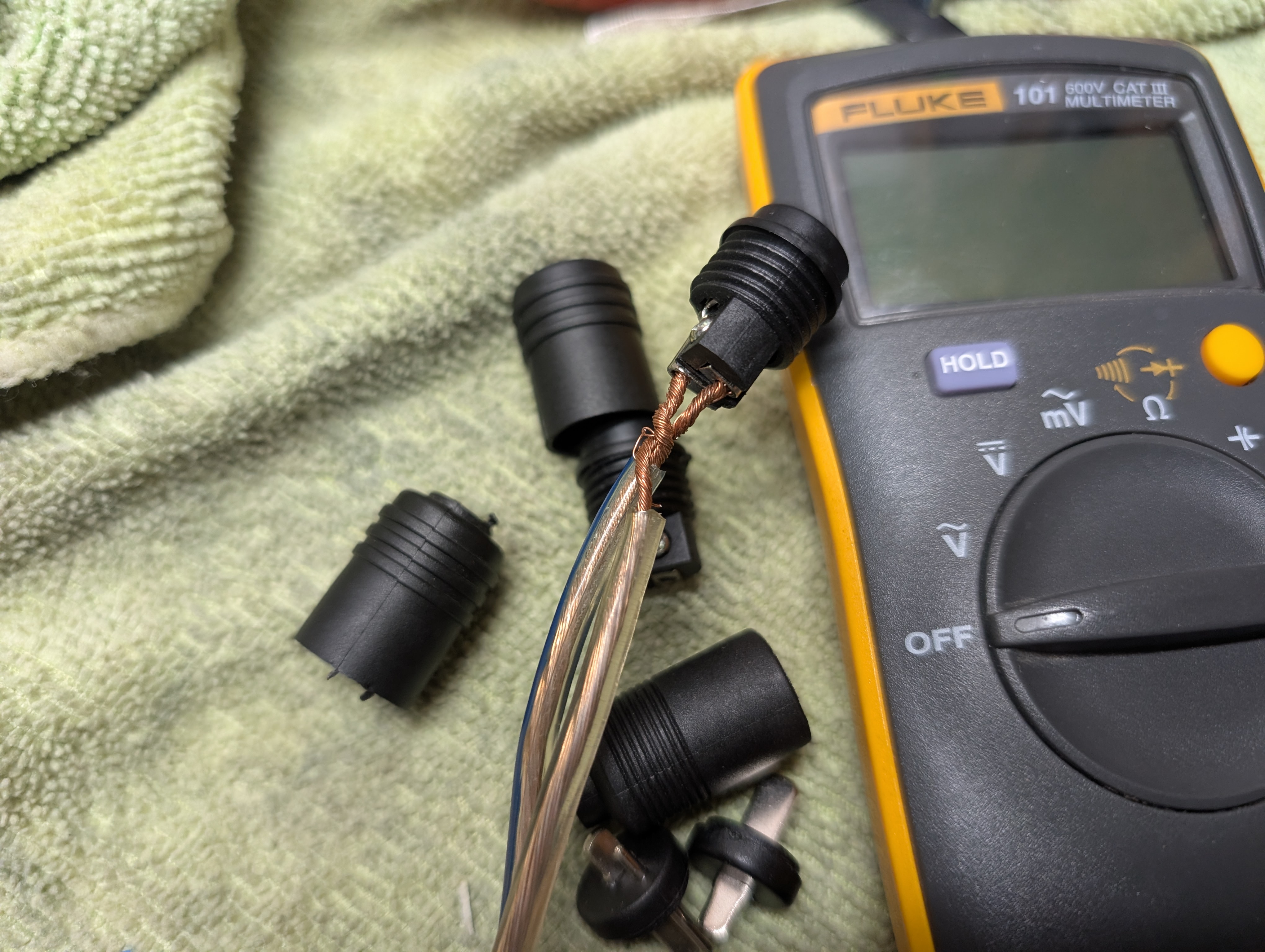
I’m talking about #47 in the schematic, in the red box:
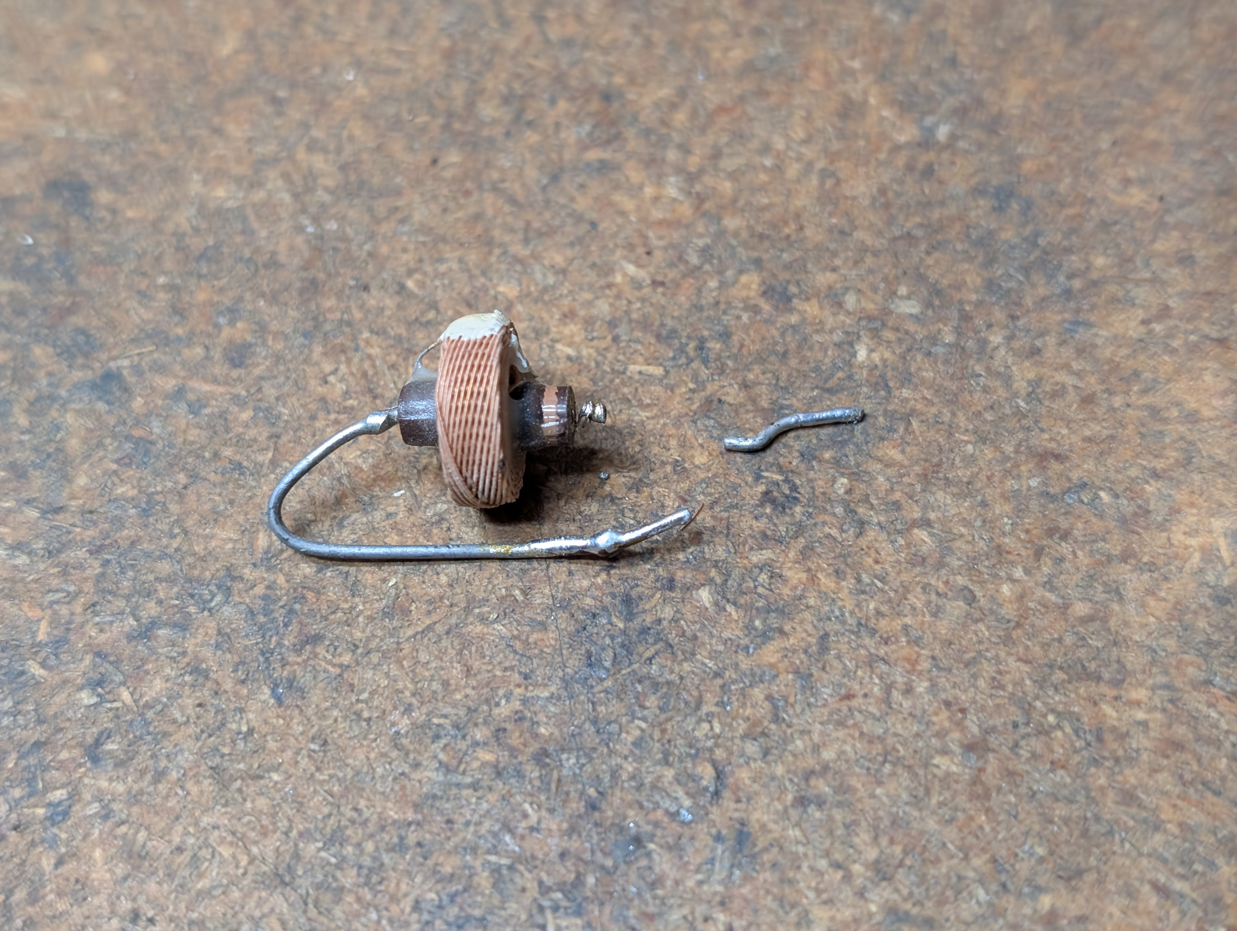
Here’s a pic of what happened … when I went to de-solder it, one of the thick mounting pins came apart. But I am pretty sure that the thick pin is not conductive, but rather it only conducts through the wound inductor wire – which I soldered back onto the pin and put back into place.
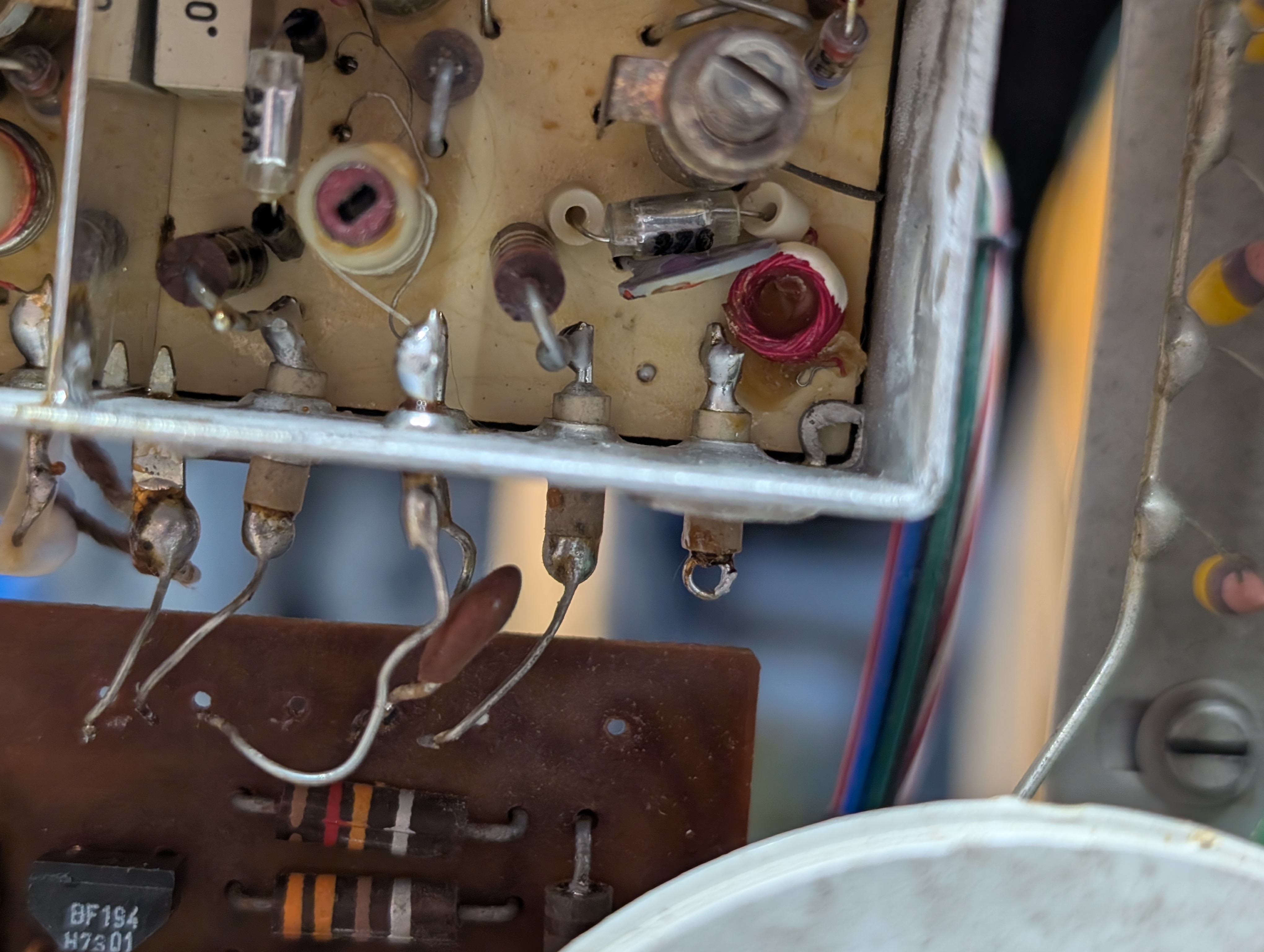
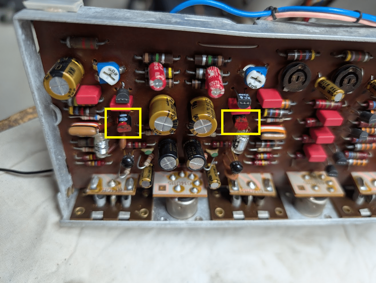
It goes here in between the empty loop on the front end and the empty hole next to it on the FM PCB:
I would suspect that if it’s preventing the appropriate voltage from reaching the capacitance diodes in the FM front end, that’s preventing the front end from reaching the ends of the frequency spectrum?However – I don’t measure any voltage loss across it. So it seems to be conducting fine.Does anyone know what voltage I SHOULD be seeing at that connection at 88MHz and at 108MHz? There’s no reference voltages in the schematic so it’s impossible to know if mine are correct or not …6 January 2026 at 18:17 in reply to: Beomaster 3000-2 Type 2402 15V Power Supply Not Activating #72386Johnny LawBRONZE MemberThen, about that distortion … found a smoking gun, R481 decided to break, screwing up the right channel’s idle current and causing the distortion.
Soldered it back together and we’re back in business w/out distortion.
I did notice that one emitter resistor is reading low idle voltage drop compared to the other one (settled on putting it at 10mV with the other one at 14mV). I don’t have any equipment sensitive enough to measure 0.15ohms so I wasn’t able to confirm whether or not it has drifted … so I just hooked it up, set idle current according to the manual and it’s back in action (again) and sounding great via Q1 (my record player) and Q2 / Tape (my CD player).The FM issue remains … the tuner range maxes out at 105kHz now, I get static when the stereo light is on, etc. Digging into that next …6 January 2026 at 18:08 in reply to: Beomaster 3000-2 Type 2402 15V Power Supply Not Activating #72383Johnny LawBRONZE MemberA combination of my stupid mistakes and the ethereal nature of all physical objects thanks to the constant and relentless erosion of the universe as we and everything we touch slowly degrades into an entropic eternity … just another Tuesday.
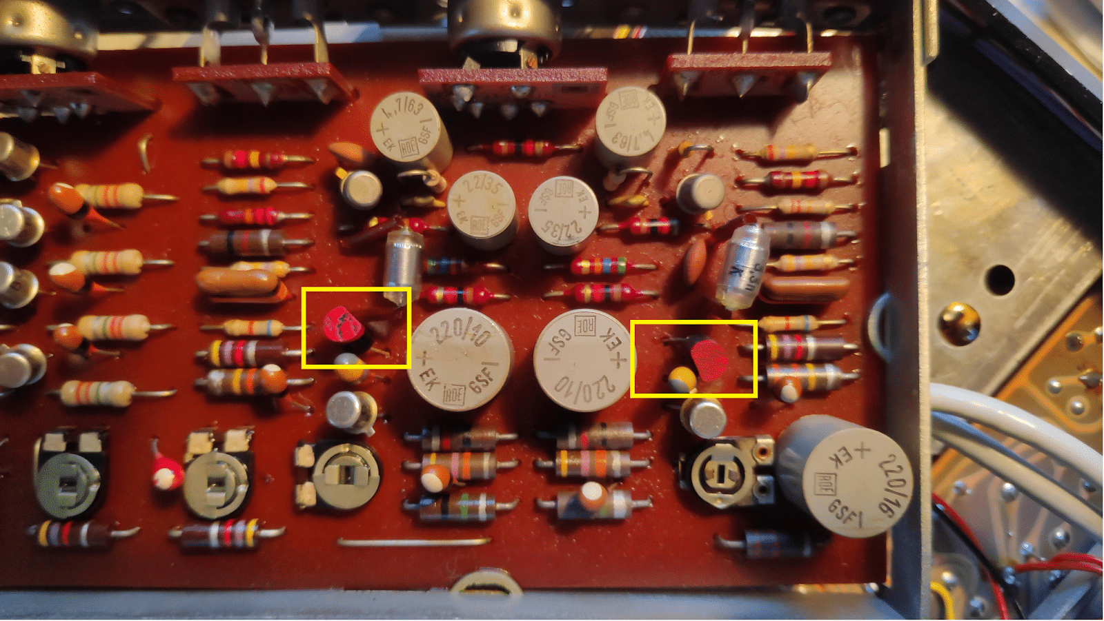
Q1 didn’t work because – surprise (to me) – the pin orientation on the PCB of TR31 and TR35 are cock-eyed relative to the package. In other words, instead of going straight into their emitter / base / collector holes – like every other transistor in this thing – they go in sideways. And also, there’s an error in the service manual. TR35’s E and B are switched! So don’t install TR35 as shown.
I.e., they are supposed to look like this (in the yellow boxes):
… and I had put mine back like this WOOPS
21 December 2025 at 21:39 in reply to: Beomaster 3000-2 Type 2402 15V Power Supply Not Activating #72053Johnny LawBRONZE MemberFirst discovery: a gift from 10-years-ago-me. (When I first acquired my 3000-2 and, I put these DIN plugs on a pair of speaker cables … but obviously didn’t think they might get twisted.) 10 year-younger me, what an idiot!
So … I guess I was playing this thing with shorted speaker cables … d’oh …
Then I discovered that listening (Tape input) via headphones has no distortion. But through speakers, distortion.
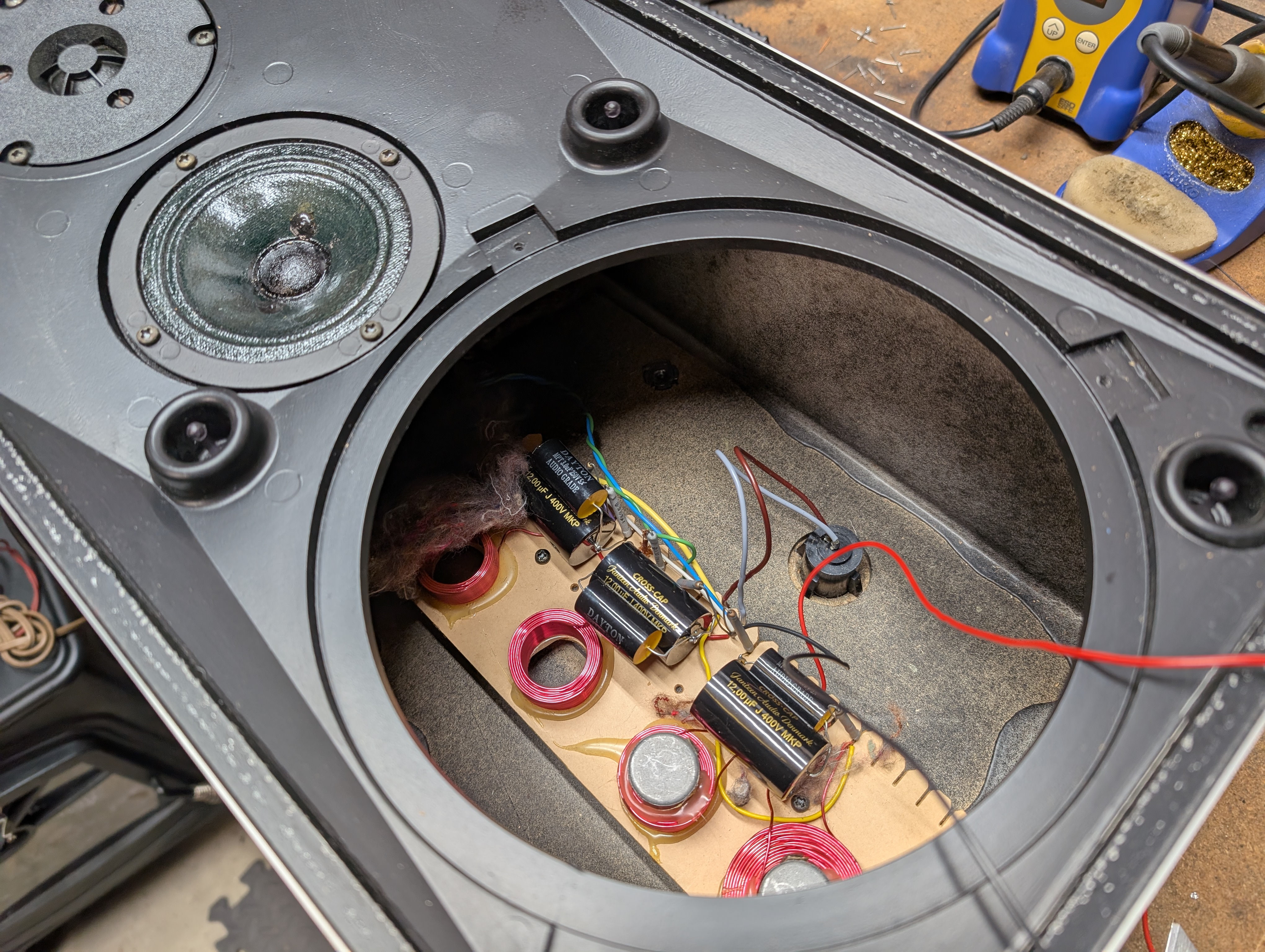
So I thought – a-ha, must be a problem with the speakers (aka I hope it’s the speakers and not the amp…).
As it turned out, I happened to have the right caps on hand thanks to an aborted re-cap project for another pair of speakers a few years ago.
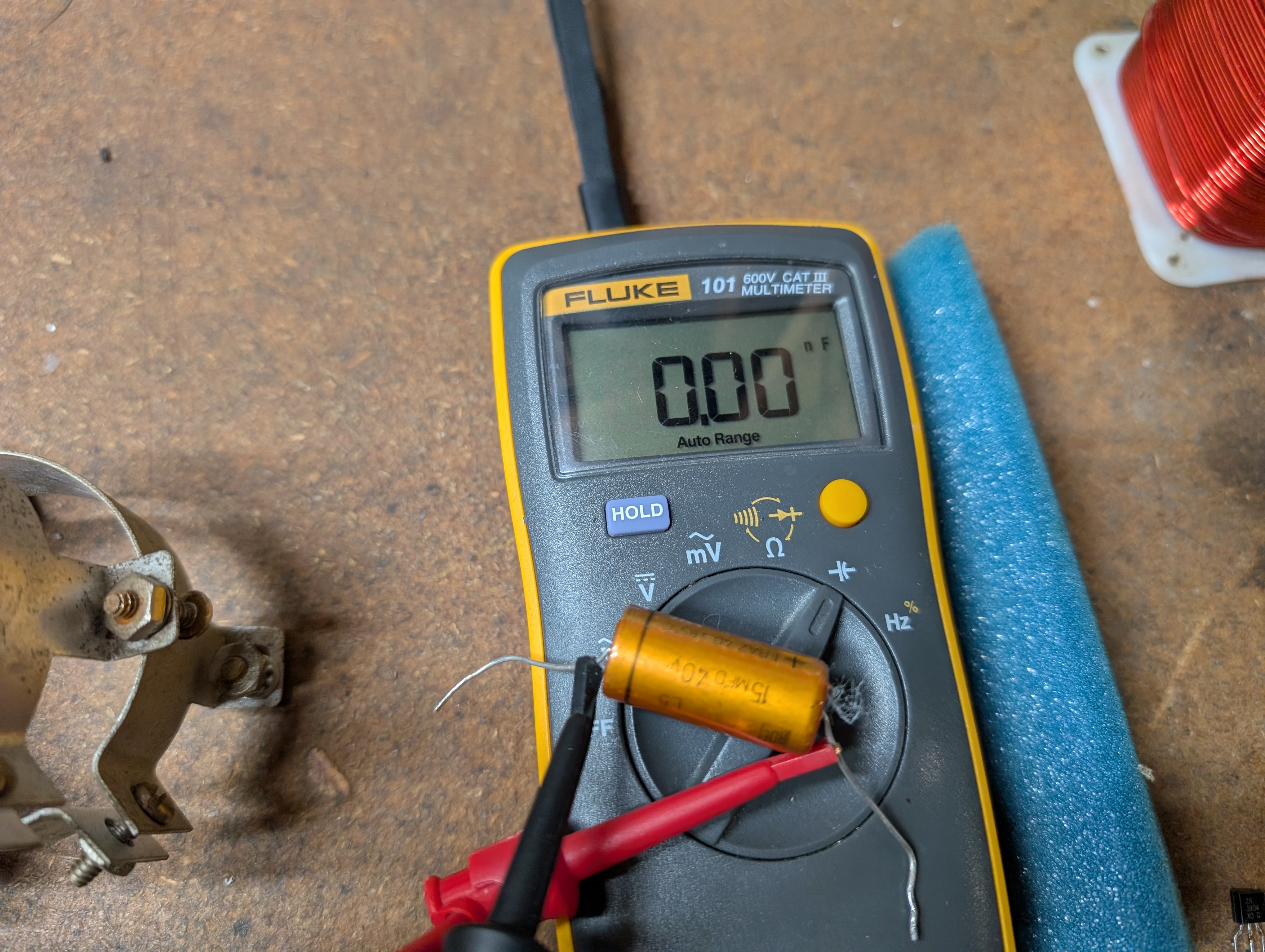
This led me down a side quest … re-capping my S45-2 speakers. Of the 6 15uF caps in the two speakers, 5 of them measured ~18uF and 1 of them measured 0uF.
The drivers and resistors measured fine … so back together the speakers went.
I also made new cables WITHOUT shorting anything … and put it all back together.Through headphones, no distortion. But as soon as I click the Speakers switch, it becomes distorted, even through the headphones, on both channels.I swapped speaker cables left to right, swapped my input left to right, and narrowed it down to distortion – only through speakers, not headphones – on the Right channel only.So now, to try to figure out what’s causing the distortion in the Right channel via Speakers but not Headphones.16 December 2025 at 03:13 in reply to: Beomaster 3000-2 Type 2402 15V Power Supply Not Activating #71965Johnny LawBRONZE MemberCraig – Yeah, nailed it!
All of the original bulbs had burnt out – aside from the tuning meter bulb – so I am using LEDs.
.. I had read about the tuner needing 12V / 0.03A discriminator bulbs … in some past thread I read. I guess that was true 🙂 So I’ll find some.
In the meantime, I’ve done a good job making a mess out of things.
Streaming audio was sounding good via the Tape input, so then I tried Q1 with my record player … but I wasn’t getting any sound out of the left channel. My first thought, since I wasn’t at my bench, was to try adjusting the level controls underneath … and in doing so, the R channel potentiometer decided to be frozen and then to tear apart completely (the part that spins along the lower metal path tore off the base).
So I took it back out to the bench to assess the damage. I removed both channels’ pots (the good L one and bad R one) and thought I could use resistors to effectively simulate a fixed pot. I used two pairs of 15kohm & 40kohm resistors (closest to 50k total as I have on hand).
I also pulled and tested all transistors in Q1 pre-amp, and all were fine. In doing so I found a broken PCB trace in the L channel – which explains the lack of sound before.
Put it all back together and now…
- No sound at all from either Q1 channel
- Sound with all other inputs is now distorted through speakers, namely bass / lower frequencies. Almost like it’s clipping. Imagine how a bass note would sound through a household fan – like if Darth Vader were speaking all the bass notes.
So … neither of those things were either expected nor are they Good Things to Happen.
I have no idea why either of those things are happening, I suppose it won’t be until the weekend that I can begin to investigate.
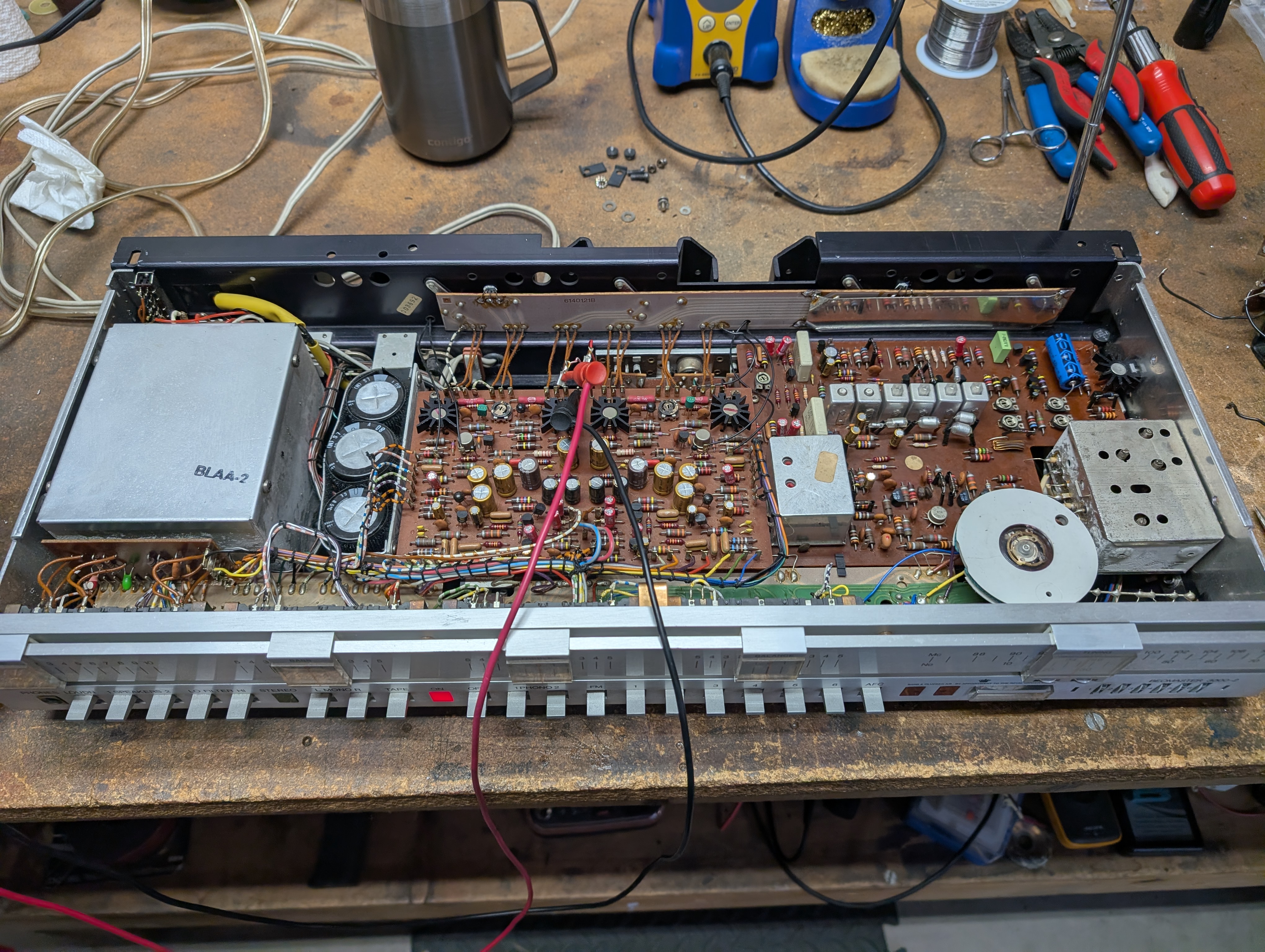
14 December 2025 at 16:05 in reply to: Beomaster 3000-2 Type 2402 15V Power Supply Not Activating #71922Johnny LawBRONZE MemberI still need to address a few things yet – mainly about the tuner, it has horrible reception and the tuning range is way off (it stops at 105MHz instead of 108MHz …) – I may start a new thread – but the amplifier itself works wonderfully now!
I dialed in the idle current to ~100mA …
Set up with my S45-2 speakers and playing its first music in decades …
Cheers!14 December 2025 at 16:00 in reply to: Beomaster 3000-2 Type 2402 15V Power Supply Not Activating #71917Johnny LawBRONZE MemberWell it took me another month but I finally figured it out.
I first disconnected and tested every single transistor and diode in the FM circuit, and didn’t find a single one of them to be bad.
Since nothing tested bad, I thought it must be a DBT issue and maybe it would work fine when plugged into the wall. So I re-assembled and plugged into the wall … only to disprove my prior hypothesis when the 15V PS wouldn’t activate.
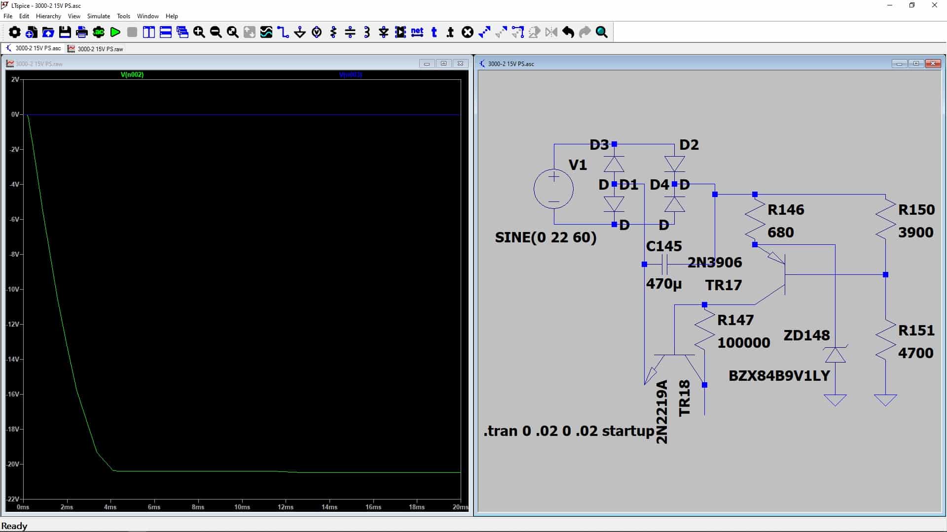
Then I started checking voltages and noticed that while the +PS was around 0V, the (-) side of C145 measured around -20V. I took a step back, scratched my chin and thought that seemed almost list the + side was grounded and the – side was not.
So I went into LTSpice and I removed the TR18C’s ground. VIOLA! The circuit acted the same (see uploaded picture).
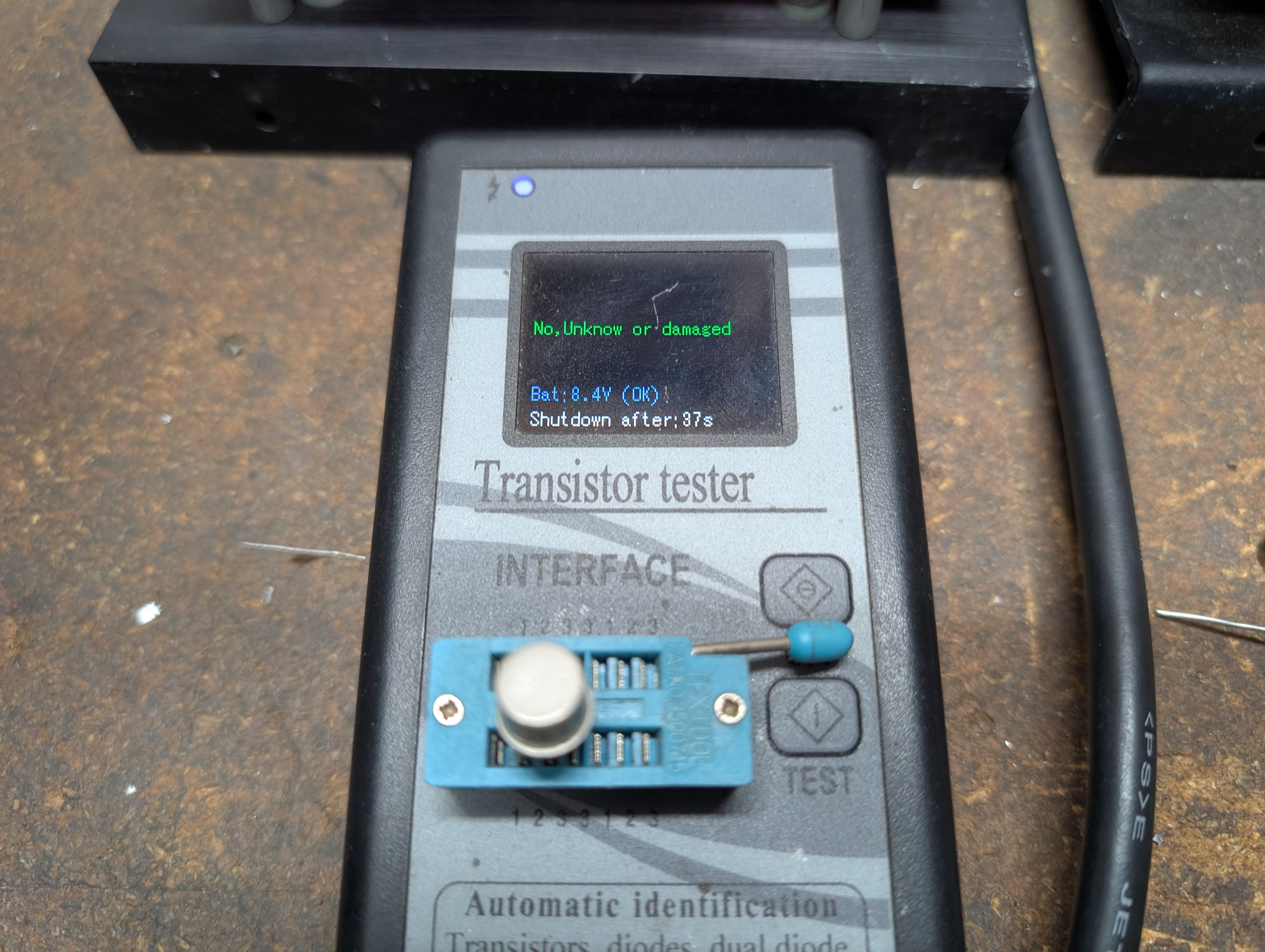
Since the physical PCB trace was fine, that must mean TR18 has an intermittent internal open.I pulled TR18 – again, this is a brand new 2N2219 – lo and behold, my transistor tester confirmed it was bad.
So I added another 2N2219 to my next Mouser order, got it, installed it, and now the 15V PS activates properly every single time.WHEW. So the whole thing was caused by a brand new device with an intermittent internal open. That was a fun one to find … I guess you can never assume new parts are OK!Attachments:
You must be logged in to view attached files.18 November 2025 at 18:18 in reply to: Beomaster 3000-2 Type 2402 15V Power Supply Not Activating #71375Johnny LawBRONZE MemberAnd also, I’m too much of a chicken to plug it straight into the wall WITH the FM circuits connected. Although, that might be a quick way to find out what’s wrong (ZAP)…
17 November 2025 at 21:58 in reply to: Beomaster 3000-2 Type 2402 15V Power Supply Not Activating #71355Johnny LawBRONZE MemberOh – I forgot to mention – into the wall directly, I am seeing 21.4V AC out of the transformer.
Via the DBT, I see around 19.6VAC when it’s at 15V, but when it gets stuck lower, the transformer is reduced to 19.1VAC from the bulb.
So – hopefully that means the transformer is OK.
17 November 2025 at 21:54 in reply to: Beomaster 3000-2 Type 2402 15V Power Supply Not Activating #71352Johnny LawBRONZE MemberAfter lengthy diddling over the weekend, I have decided to conclude that it’s the DBT causing the 15V power supply to sometimes not activate, but only when isolated from the tuner’s IF and discriminator circuits.
I had been using a 53W bulb – and it had behaved as described above.
Over the weekend, with the 15V PS circuit electrically isolated (i.e., everything connected to it de-soldered), and plugged directly into the wall, I see 15V EVERY SINGLE TIME I power the unit on. I must have cycled the power on and off 50 times or so. I saw 15V every single time.
Then I found a 100W bulb and installed it in my DBT. Through the 100W bulb, I cycled on-off-on-off and again saw 15V every single time.
Feeling confident, I then soldered back into place the jumper leading from the power supply to the IF and discriminator boards (see attached image).
Note that the pre-amp and all bulbs are still disconnected.
With the FM circuitry hooked back up, via the 100W bulb, power on and I only see 0.02V at the 15V power supply!!If I de-solder the jumper, strangely, the first couple times I power on (via the DBT), the PS gets stuck at ~1.8V … but off-on-off-on a few times and it comes back. (WHY?? No idea …)So anyway – I figure the next thing to try to figure out is what’s dragging the voltage down in the IF & discriminator circuits.I removed and checked TR19, TR20, TR21, and TR22, all are OK and no change to the 0.02V with them out of circuit.Onwards – I figure I’ll keep checking devices until I find a short to ground? But any other thoughts highly appreciated …Attachments:
You must be logged in to view attached files.12 November 2025 at 19:49 in reply to: Beomaster 3000-2 Type 2402 15V Power Supply Not Activating #71119Johnny LawBRONZE MemberI have even tried to alter values / remove grounds / try different things in LTSpice to try to duplicate/simluate the behavior, but nothing so far produces the same values.
12 November 2025 at 19:47 in reply to: Beomaster 3000-2 Type 2402 15V Power Supply Not Activating #71118Johnny LawBRONZE MemberYeah, I am really at my wit’s end. Everything tests good, measures OK, and yet it still doesn’t work. (Well, once it works, it works fine, but it doesn’t always work unless I cycle the power off and on!)
I tried while plugged directly into the wall, but see the same behavior as through the DBT.
The rectifier B30C350 is a new B40C1500.
TR17 was originally a BC212B and is now a new BC212B (I have the original still on the bench, it tests OK).
TR178 was originally a BC119 and is now a new 2N2219 (this is a TO39 package device, the original was shorted, got red hot under operation, and had a cold solder joint that I discovered).
ZD148 is the original which works fine, although I have at various times put in a new NZX9V1 Zener diode, but the circuit does the same thing with the new or original one in place.
C145 is a new Vishay 138AML axial 470uF / 40V.
The resistors are either original or were replaced by metal film before my time. All measure correct values out of circuit.
All grounds are good.I am totally at a loss. I will keep poking around and taking measurements and hoping to find some inspiration …
11 November 2025 at 18:26 in reply to: Beomaster 3000-2 Type 2402 15V Power Supply Not Activating #71082Johnny LawBRONZE MemberWish it were that easy – turns out, when the PS isn’t activating, TR17 is only seeing ~0.4V B to E.
The attached image shows my Mastech is on the +PS, and my Fluke is on TR17 B to E.
So it’s not a TR17 issue. It’s a current issue … for some reason, it’s not seeing enough of a drop across R150 (even though R150 measures correctly) to activate TR17.Here’s where things get weirder … when I turn the unit OFF, TR17E-B BRIEFLY hits 0.6V+ and activates! So while the unit turns off, the 15V PS turns ON for a moment before then going dead.I managed to snap a pic when this happens.Attachments:
You must be logged in to view attached files.9 November 2025 at 15:55 in reply to: Beomaster 3000-2 Type 2402 15V Power Supply Not Activating #71003Johnny LawBRONZE MemberGreat idea … I had disconnected the pre-amp, but I had not disconnected it from the FM circuitry! So I lifted various leads of all components getting fed by the + side trace of C145.
With the +15v PS completely isolated … it turns on correctly MOST of the time.
When it gets stuck, now it’s stuck at around +1.8V instead of the +0.06V I was seeing before … when this happens if I touch anything in the circuit with my DMM lead, it switches on fully. (This obviously implicates TR17 which SHOULD activate with that much voltage at its base …)
Once it does switch on to the full +15V, I can turn it off and on again repeatedly and it always activates correctly.
I let it sit off overnight, and tried it this morning: it immediately went to the full +15V (I was wondering if maybe discharged capacitors had something to do with it … apparently not).
So from here, two things: 1 – why won’t it turn on 1-5% of the time; 2 – what’s shorting out in the FM circuit?
Onwards!
7 November 2025 at 02:22 in reply to: Beomaster 3000-2 Type 2402 15V Power Supply Not Activating #70962Johnny LawBRONZE MemberYeah, I’ve been checking it over for longer than I care to admit.
Originally, I found quite a few, notably including TR18.
Everything has been re-flowed and/or checked … no harm in checking again I suppose!
Thanks for the input … looking forward to finding the issue and shaking my head, looking back on my troubleshooting, whatever it ends up being …
-
AuthorPosts