Forum Replies Created
-
AuthorPosts
-
 AryBRONZE Member
ive noticed also that if the amp has been in standby for a while and i take it out there is a big discharge of something audible though the speakers. Possibly another hint to the problem above perhaps.
AryBRONZE MemberThanks Glitch
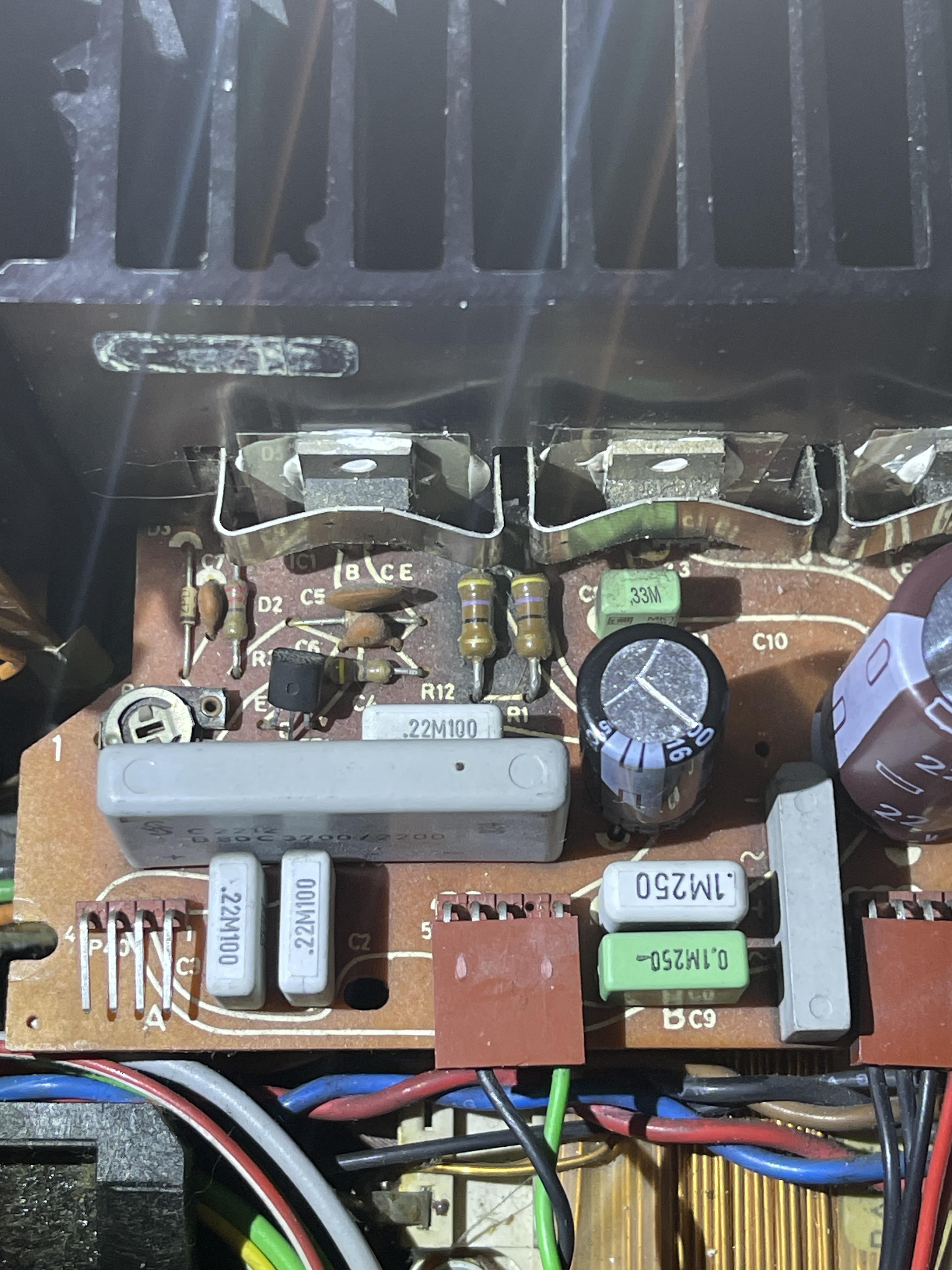
you are right sometimes just breathing on one of these old trimmers makes them fall apart. I replaced all the trimmers on the pcb 16 and 6, made the adjustments and its up and running again. its still not very happy though…. the power supply is running warm mainly 16r12 and ic1 even on standby it gets above luke warm even the transformer so im assuming something is drawing current anyway i made a new post for that.
AryBRONZE MemberHi All
Been working on a whole bunch of stuff lately but as of now my trusty beomaster 6000 has been getting hotter then usual so figuring that out. Past weeks ive also recapped a CdX and what a wonderful player it is.

 AryBRONZE Member
If your budget can stretch it I would opt for a Wiim Ultra. It has a phono preamp built in (not the best but perfectly capable) and you gain all the modern streaming functions, EQ and a remote. My Wiim pro works perfectly on a set 8000 I had so the ultra will do even better (better built in DAC) if you want to stay analoge then the option is a phono pre amp with volume control. The volume control is key as the Beolab speakers of that generation don’t have any volume control built in as you and your neighbors might have found out.
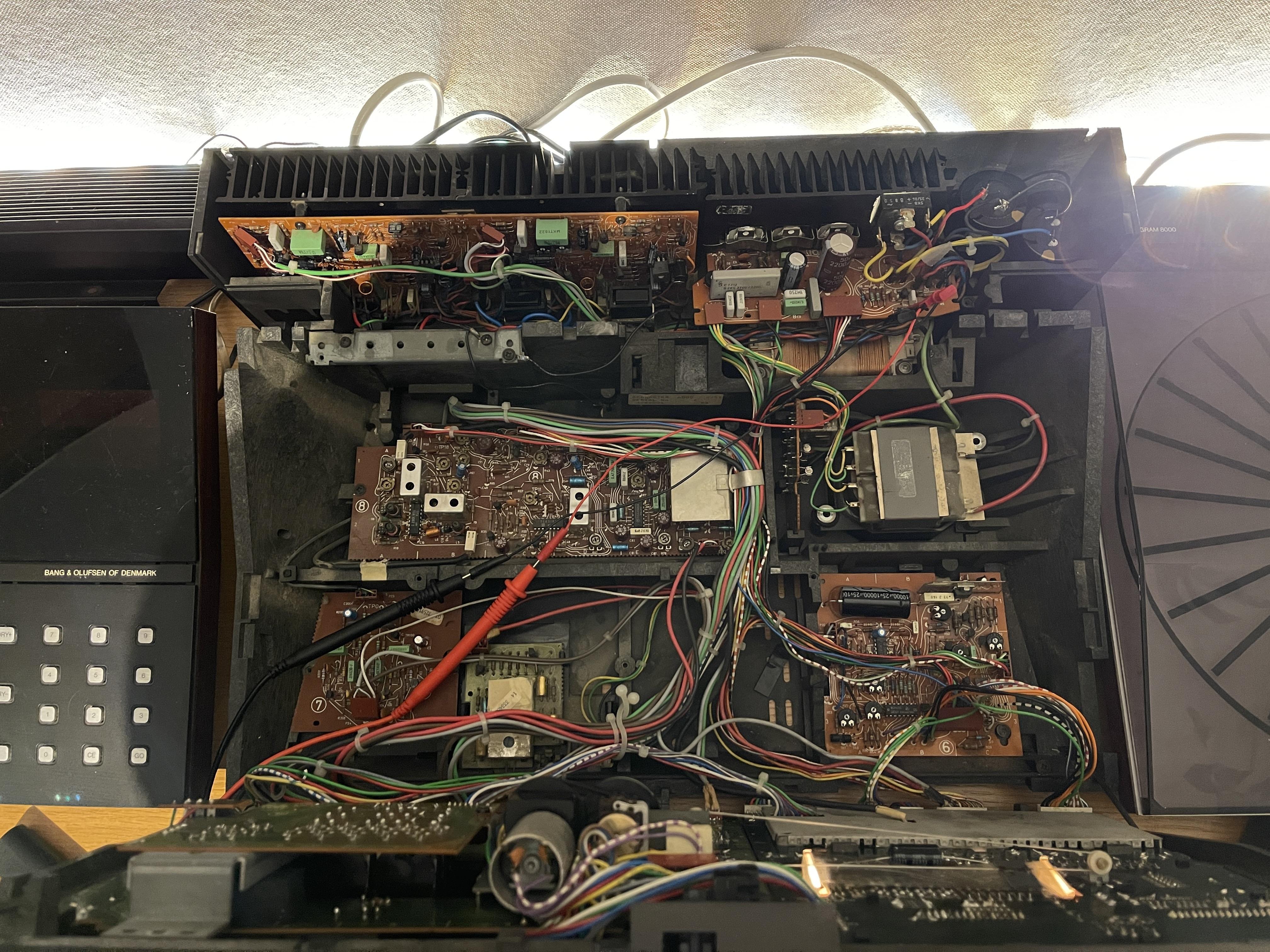
AryBRONZE MemberAlright, so I’ve been testing the Beomaster.
The unit seems to function properly overall (aside from the radio board and the blown bulbs for the radio signal on the display board). Disconnecting PCB 8 doesn’t affect the following measurements at all.
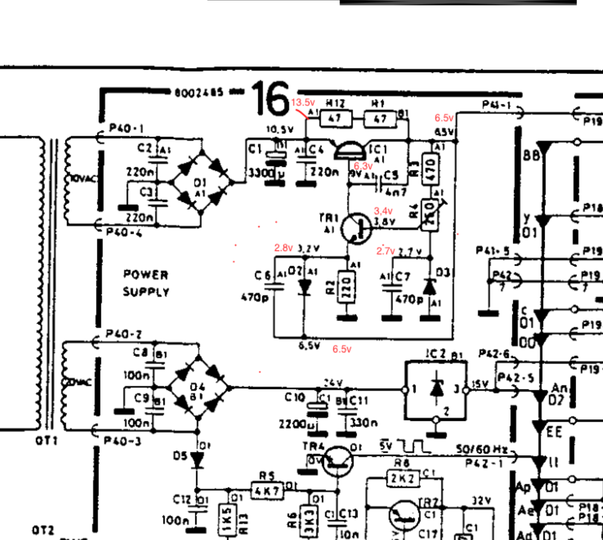
I’ve gone through the power supply and attached the schematic with the voltages I measured. It closely resembles an old post by Sonavor, which I’ve linked here: https://archivedforum.beoworld.org/forums/t/42628.aspx?PageIndex=5
Before I remove the power supply to test components out of circuit, I wanted to ask—has anyone encountered this issue before or have any pointers on where to focus?
I adjusted the trimmer R4 to get a 6.5V output, which lowers the voltage at the base of TR1. This significantly reduces the heat buildup, but I’m sure this is a symptom of a deeper issue. ive also adjusted and replaced all trimmers on the PCB 6 board.
Any thoughts? Would love to hear any insights before diving in further!
Cheers,

Attachments:
You must be logged in to view attached files.AryBRONZE MemberHi Martin
Thanks for your reply—I know you must be busy, so I appreciate it!
I can confirm that the power amp section is completely off, with no current flowing through, and the cooling fins remain cold. I also checked the fuse for continuity, and it’s working fine, so the issue must be elsewhere on another PCB.
Looking at the schematics, R12 appears to be linked to 6R11, a trimmer on the standby PCB, which seems to adjust something on the radio board (PCB8, if I’m not mistaken). Maybe you or someone else here can shed some light on this, as while I’m experienced with electronics, vintage radio circuitry is admittedly not my strong suit!
I also checked whether the radio works, but it doesn’t—I can’t seem to get any tuning. If I remember correctly, Martin, you still sell a part that can restore this functionality? That said, I’m not particularly interested in using the radio, but if fixing it is necessary to resolve the issue, then so be it.
Wishing everyone a great evening—or Friday, depending on when you read this!
Ary
AryBRONZE MemberHi Noid
I hope by now that you managed to repair the woofers and orderd a recap kit from Dillen. I can only highly recommend changing out the caps as it opens up the speakers considerably and realy make them sing. they are a wonderfull pair and worth keeping. If hooked up to a good amp (preferably a restored beomaster from the same era haha) they will surprise you quite a bit! Also I found putting them on the original stands made quite a diffrence.
AryBRONZE MemberHi Michael
This would be great for alot of people. Could you please provide a name of the seller or a link?
AryBRONZE MemberSorry for the late reply. Over the past few days I’ve been checking the voltages so I started by measuring the resistors on PCB1 connected to the speed sensor. I found that resistors R46 and R47 both showed only 3 volts. I believe this should be 15v. So I started measuring 0TR1, I measured 22 volts going in and 0.03 out on the collector (tip32 middle pin). Then I noticed that 0IC1 starts overheating to the point of not being able to touch it. (desoldering it from the board showed the same output on tip31) Other things I measured were the whole path from P4-6 to -> C44 and from P4-8 -> R46 that leads to P3-4 and on the other end to 1Ic1 P12 and TR28 everything in this path seems to be working. I do have a question about resistor 102 and 49. Both seem to be the 1 million ohm rating and I’m not sure how to test these. With my multimeter set at 200k r49 reads 38.2 and r102 reads 104. Maybe somebody can tell me if I’m doing this correctly or if I’m being stupid? Then I checked the path from fuse 1 (on PCB1) that leads to P2-5 and on the other end leads to R75 -> TR17E. I notice that R75 only reads 1.9k in resistance. Could this be my problem? I know a non working TIP31 will not give me the 15v circuit but I feel like it was working before and it has blown so i feel like something else is seriously wrong
I do notice that multiple threads on this forum go dead when the problem states the 0.0.0.0 problem? Not sure why that is?
Still trying to figure it out. Very grateful for anyone who lands a thought on this.
Ary
AryBRONZE MemberGood evening Martin and thank you for your response. Ive gone and checked the continuity from the sensor to pin 40 on the cpu and where it splits off from Ic1 to the collector of TR9 and P5 pin 1. All seems to check out. Tomorrow I will go an check some voltages across that path. what I can tell is that right now im seeing 0.6V across the on red and green to ground, but that might not mean anything I do not know. Ive been working on this for 3 weeks and learning about this amazing machine as I go along. I do not own an scope as of yet. I did replace all the capacitors in the kit. I hope I didn’t complicate things more by hoping the capacitors change was gonna fix all my issues. 🙂 And shamingly so i have a strong suspicion the problem of having +24 on c29 and not – is due to my error with the meter. I guess that is good news. I also forgot to note that the display reads 0.0.0.0
-
AuthorPosts