Home › Forums › Product Discussion & Questions › Other › Wanted: information about BeoCIM product
- This topic has 3 replies, 2 voices, and was last updated 1 year, 4 months ago by
Madskp.
-
AuthorPosts
-
3 August 2024 at 17:39 #57970
Hello.
Couple of years ago while looking for B&O test equipment, I came across this very mysterious unit (bought here on Beoworld, shipped from US in 2018). It has the red serial number label which I’ve read means it was owned/used by B&O themselves, and/or being a prototype/pre-production unit.
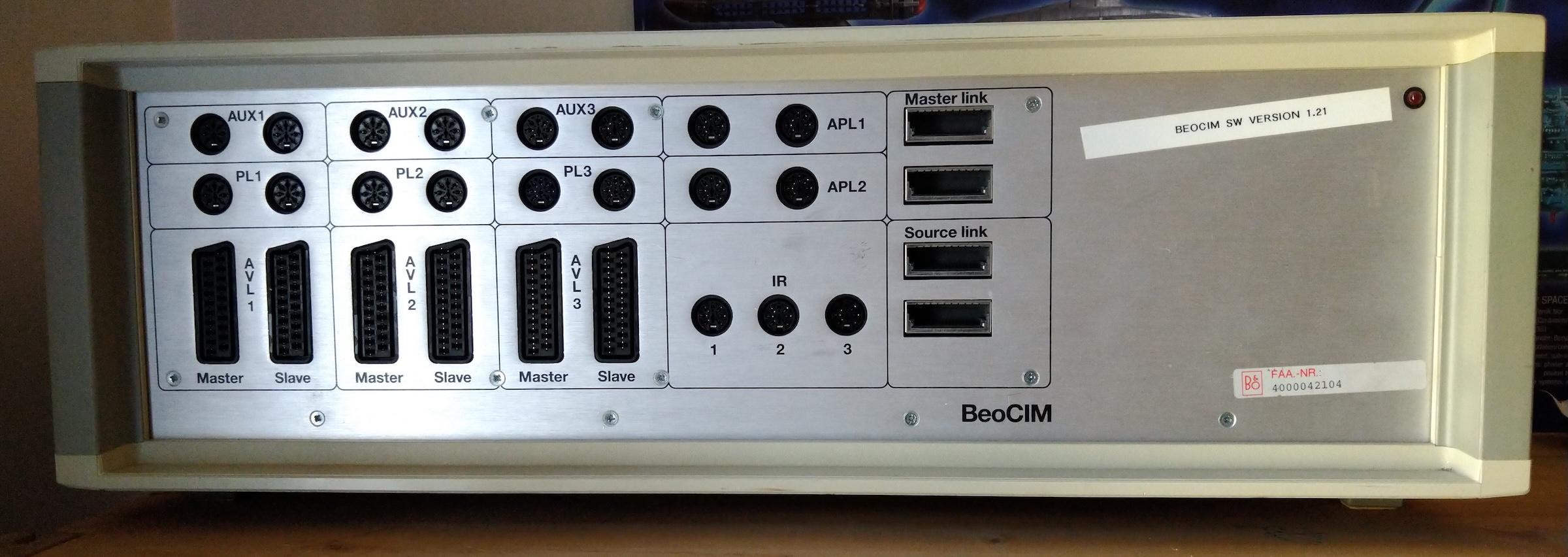
It’s branded as “BeoCIM”, which I am not sure what it stands for. Simulator? Searching the name brings up absolutely nothing.
The front panel has a number of I/O ports:
On the rear is just an IEC mains input and a serial port (of which I have not been able to get anything out, although my testing was only brief).
There are two EPROMs inside, I’ve dumped the contents. The only readable string I could see was “1.21 22-apr-98 MSH” which matches the firmware version sticker on the front panel.
The seller provided me with this insight about the unit:
The unit came from our offices in Chicago (I work for B&O) when we moved to a new location almost 10 years ago. We were going to throw it away since no one is testing anything analog any longer, but I stopped that thinking maybe we would need to use it still one day. We’ll that day has come and gone and no one needs/wants it any longer. I figured someone who is collecting or repairing old kit would want it vs. feeding it to the trash compactor.
I am not sure on weather or not it runs on special SW, but that would be fair to assume. I guess you’ll know once you connect into the port.
The unit is about 21-1/2″ long and weighs a little over 14 lbs not in packing box. The machine is 220v as was most all of our test equipment when we had the facilities as B&O were not going to waste money converting the natural 220v equipment to 110v. I put the sticker on the unit so no one would forget that the unit is a 220v.
Unfortunately, my knowledge on that product ends at what it is. When it was in a working environment it was on lab desks in a rack with scopes etc. I don’t recall something needing to be master connected to the unit, but I honestly have no idea. I know it was primarily used in the AvantCRT/AV9000/MX/BSys1 days.
Our best guess was that this might be something do with testing TV chassis’ during production, but it’s just a guess.
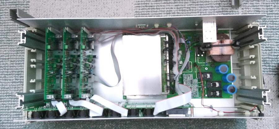
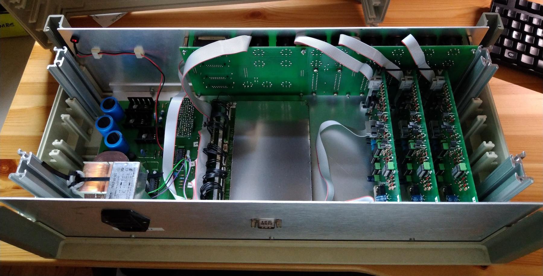
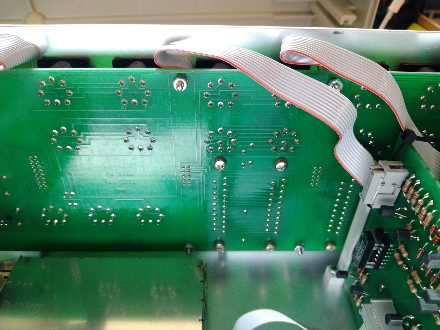
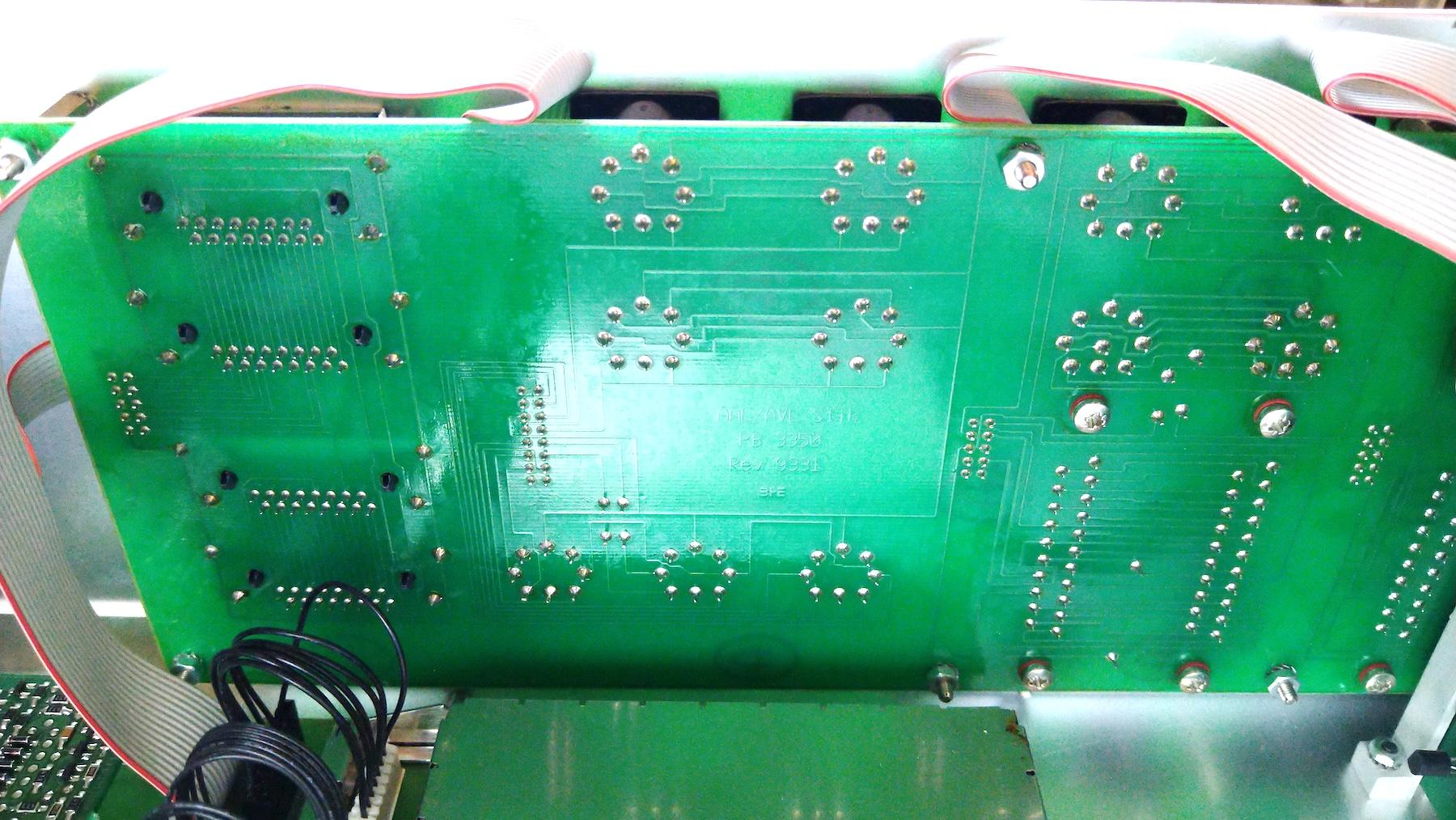
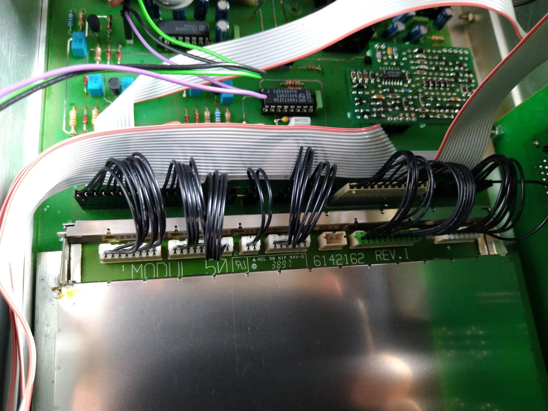
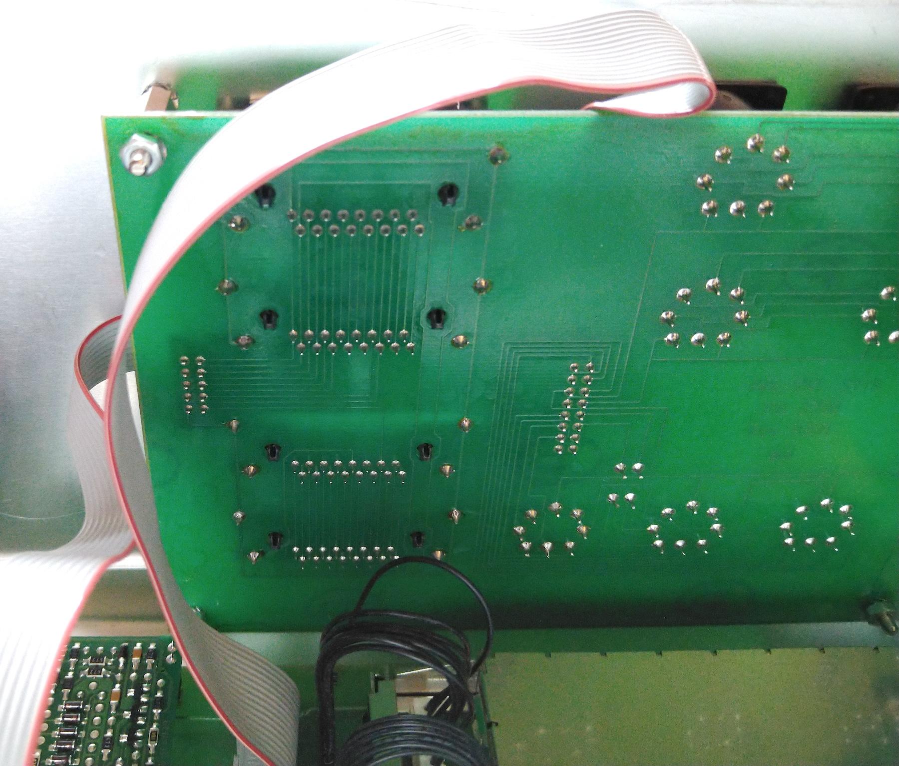
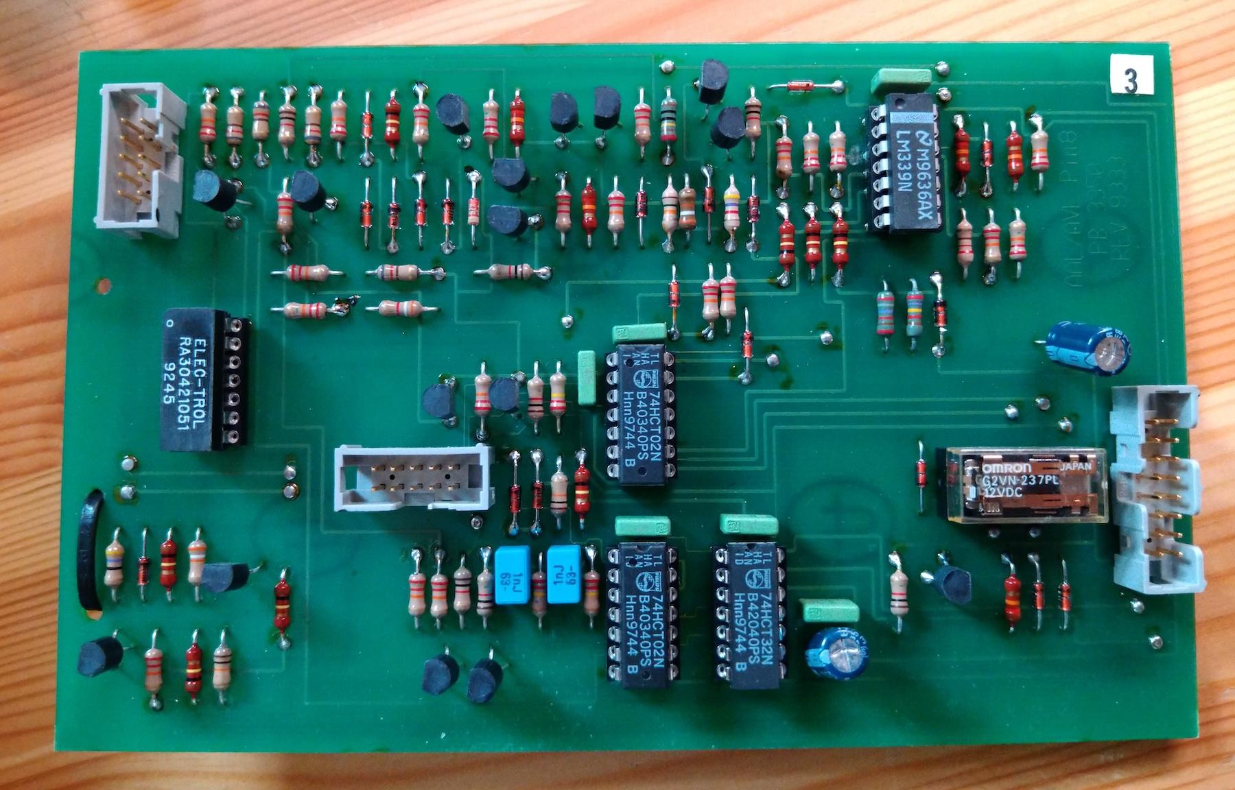
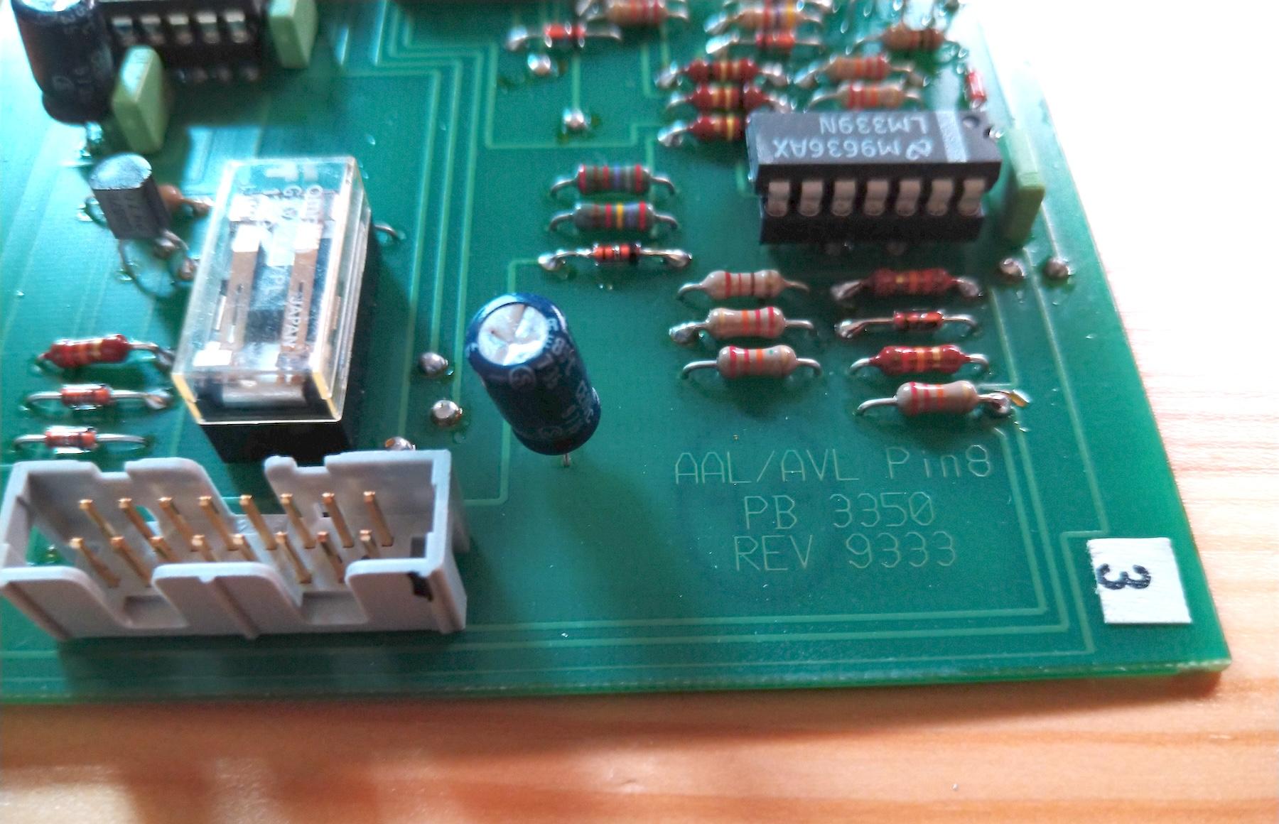
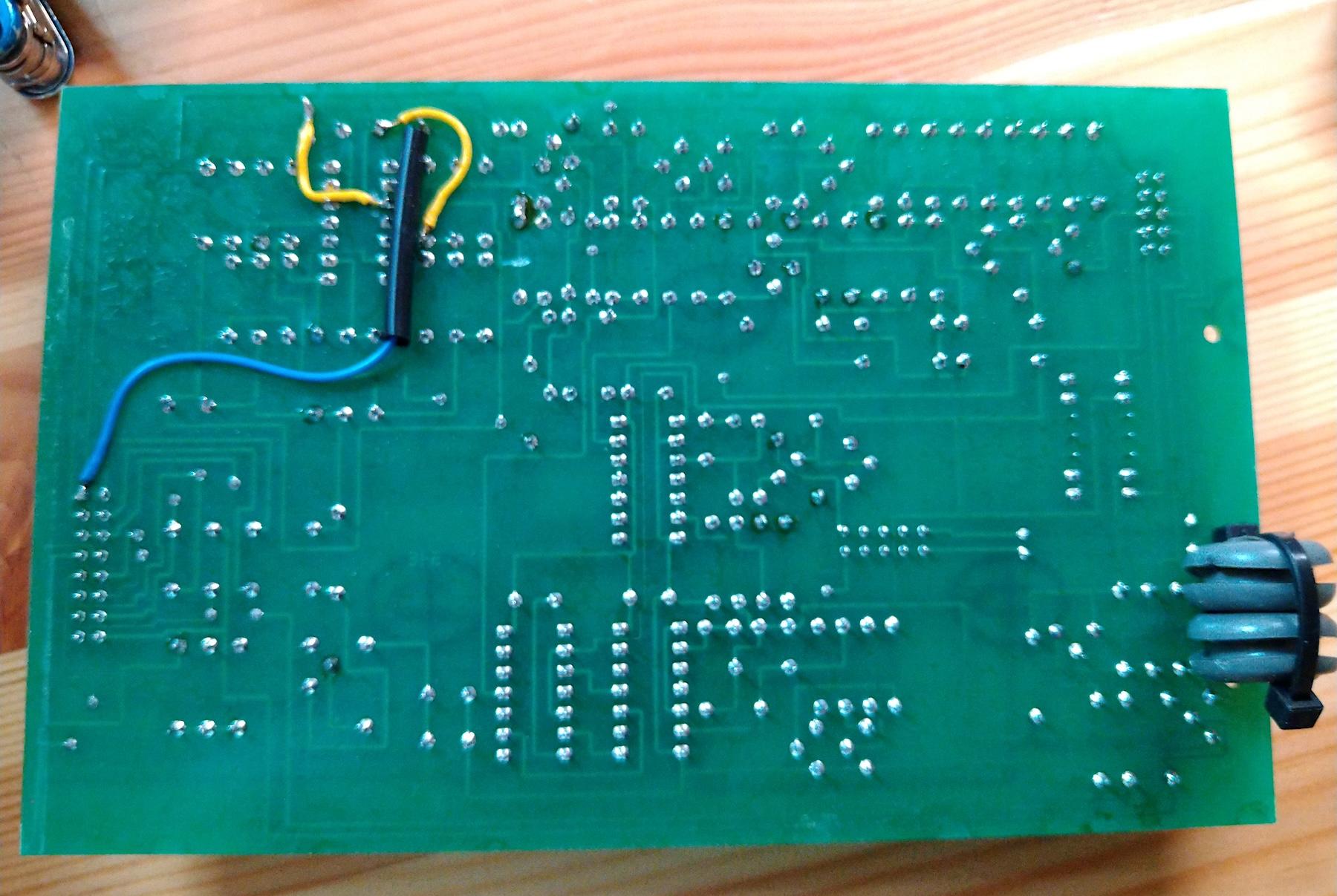
Couple more pics from the inside:
I can’t imagine these were made in huge numbers, but for that it seems quite well-built. The case appears to be a generic off-the-shelf plastic case.
I’d be most grateful to hear if anyone can shed any light on what these units are and how and where they were used. This has been sitting on my shelf for years now and I am hoping to have another go at cracking it’s mystery at some point, but so far I’ve come up with nothing.
Location: Helsinki - Finland
My B&O Icons:
4 August 2024 at 18:51 #57995Madskp
GOLD MemberThis unit is very intriguing.
I have been looking at the picture of the front several times since you posted, and I am wondering about the 3 columns of connectors named 1, 2 and 3 for both AUX, PL and AVL, and also the labeling master and slave in the bottom of the scart connectors.
Can you see if the connctors in the single columns (for example 1) are directly connected internally so they work as a passthrough or if they go through some circytry on the board? This could indicate wheether alle types of connectors in one column. are both master and slave
I wonder if the IR sockets might be for direct use with the 7 pin DIN IR connectors on the round IR eyes for Beolink active and Passive.
Location: Denmark
11 August 2024 at 14:46 #58162I remember at least thinking about testing one of those round IR eyes, can’t remember if I tried (and it did nothing).
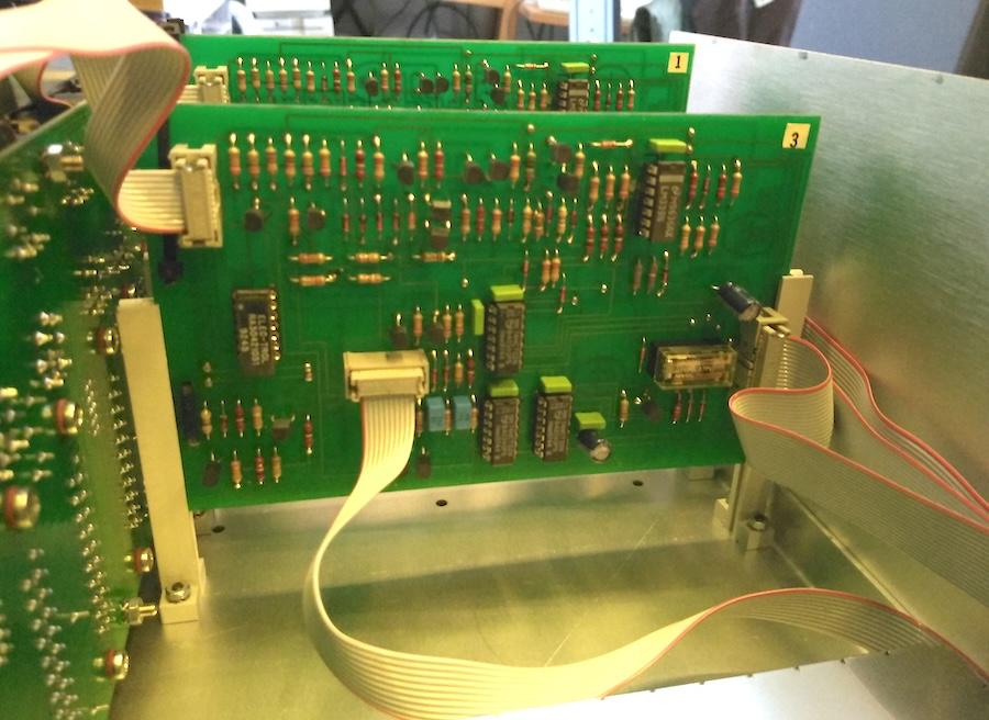
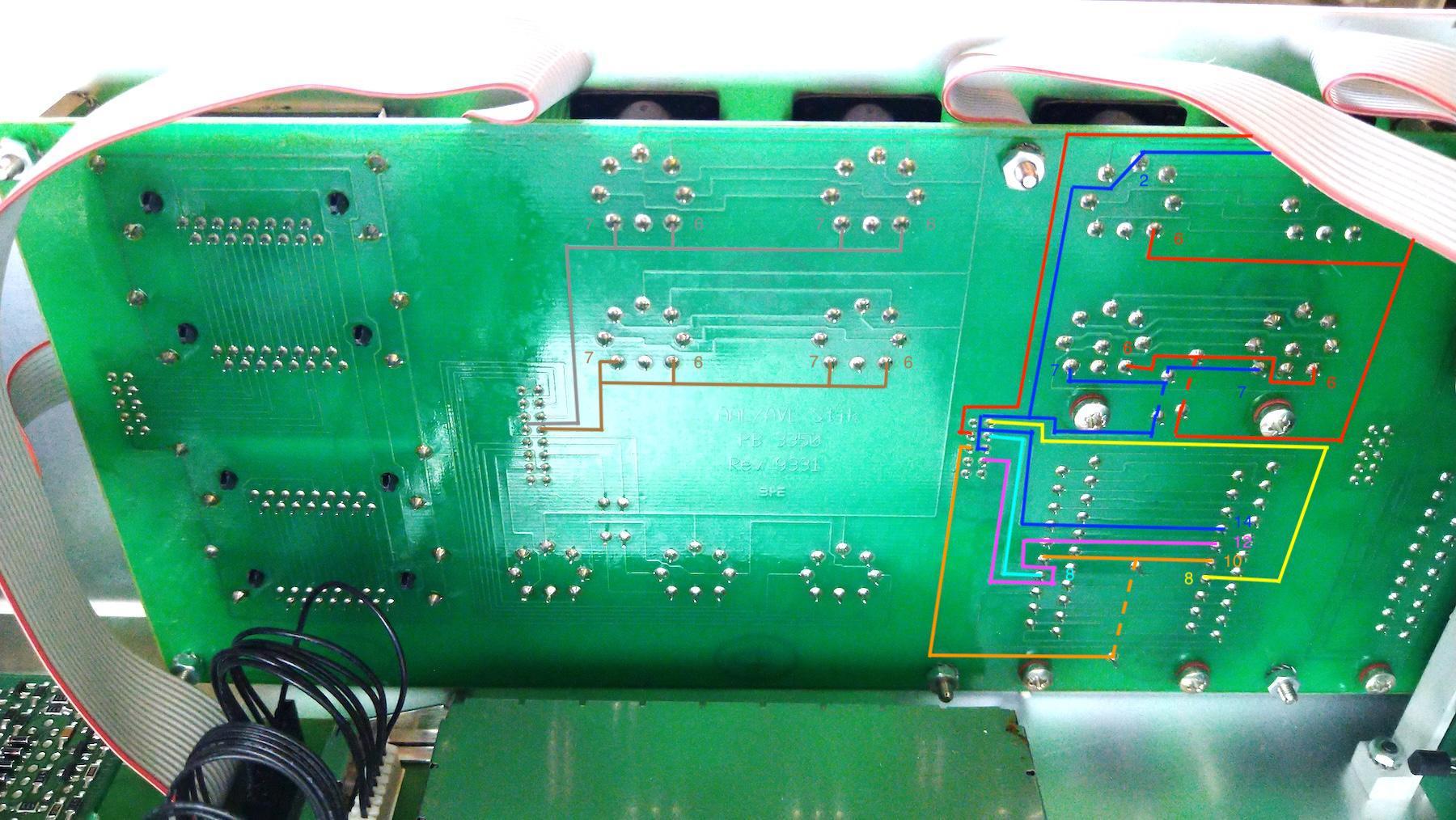
Here are some more pictures of the boards. The front panel is a bit tricky to remove, but from the rear the traces (at least the ones on that side, there might be more on the front) show. The three colums seem to go into the flat cables to go into the three identical boards so it looks like the colums are independent. I’d presume most of the audio/video are just pass-thru, and the boads mainly relate to the datapins on the different buses.
Serial port has only the usual pins 2, 3 (RX/TX) and 5 (GND) connected.
Location: Helsinki - Finland
My B&O Icons:
13 August 2024 at 08:33 #58233Madskp
GOLD MemberI’d presume most of the audio/video are just pass-thru, and the boards mainly relate to the datapins on the different buses.
Just for fun I have tried to look at the traces on some of the ports, and indeed the audio and Video parts are just passthrough between the two corresponding connectors in each column.
Datapins from AUX and PL ports seems to be connected as well as the ground connections on them indication that the AUX ports are for datalink86/MCL data signals
The apl1 and apl2 connectors seems to have pin 6 and 7 connected indicating that it is datalink 80 for connection of a Beocord/Beogram/Beogram CD as they can use both pins for data.
The Svarct connections (AVL) also have all it’s datapins connected although as far as I can tell from the photos pin 8 might not be passed through between the two scart connectors
Hope this can be useful for further investigation on what this thing was used for
Location: Denmark
-
AuthorPosts
- You must be logged in to reply to this topic.


